EP1288324A2 - A method of manufacturing a fibre reinforced metal component - Google Patents
A method of manufacturing a fibre reinforced metal component Download PDFInfo
- Publication number
- EP1288324A2 EP1288324A2 EP02255206A EP02255206A EP1288324A2 EP 1288324 A2 EP1288324 A2 EP 1288324A2 EP 02255206 A EP02255206 A EP 02255206A EP 02255206 A EP02255206 A EP 02255206A EP 1288324 A2 EP1288324 A2 EP 1288324A2
- Authority
- EP
- European Patent Office
- Prior art keywords
- metallic
- circumferentially extending
- fibre
- metal
- coated
- Prior art date
- Legal status (The legal status is an assumption and is not a legal conclusion. Google has not performed a legal analysis and makes no representation as to the accuracy of the status listed.)
- Granted
Links
Images


Classifications
-
- C—CHEMISTRY; METALLURGY
- C22—METALLURGY; FERROUS OR NON-FERROUS ALLOYS; TREATMENT OF ALLOYS OR NON-FERROUS METALS
- C22C—ALLOYS
- C22C47/00—Making alloys containing metallic or non-metallic fibres or filaments
- C22C47/02—Pretreatment of the fibres or filaments
- C22C47/06—Pretreatment of the fibres or filaments by forming the fibres or filaments into a preformed structure, e.g. using a temporary binder to form a mat-like element
- C22C47/062—Pretreatment of the fibres or filaments by forming the fibres or filaments into a preformed structure, e.g. using a temporary binder to form a mat-like element from wires or filaments only
- C22C47/064—Winding wires
-
- C—CHEMISTRY; METALLURGY
- C22—METALLURGY; FERROUS OR NON-FERROUS ALLOYS; TREATMENT OF ALLOYS OR NON-FERROUS METALS
- C22C—ALLOYS
- C22C47/00—Making alloys containing metallic or non-metallic fibres or filaments
-
- C—CHEMISTRY; METALLURGY
- C22—METALLURGY; FERROUS OR NON-FERROUS ALLOYS; TREATMENT OF ALLOYS OR NON-FERROUS METALS
- C22C—ALLOYS
- C22C47/00—Making alloys containing metallic or non-metallic fibres or filaments
- C22C47/02—Pretreatment of the fibres or filaments
- C22C47/06—Pretreatment of the fibres or filaments by forming the fibres or filaments into a preformed structure, e.g. using a temporary binder to form a mat-like element
- C22C47/062—Pretreatment of the fibres or filaments by forming the fibres or filaments into a preformed structure, e.g. using a temporary binder to form a mat-like element from wires or filaments only
- C22C47/068—Aligning wires
-
- C—CHEMISTRY; METALLURGY
- C22—METALLURGY; FERROUS OR NON-FERROUS ALLOYS; TREATMENT OF ALLOYS OR NON-FERROUS METALS
- C22C—ALLOYS
- C22C47/00—Making alloys containing metallic or non-metallic fibres or filaments
- C22C47/20—Making alloys containing metallic or non-metallic fibres or filaments by subjecting to pressure and heat an assembly comprising at least one metal layer or sheet and one layer of fibres or filaments
-
- B—PERFORMING OPERATIONS; TRANSPORTING
- B22—CASTING; POWDER METALLURGY
- B22F—WORKING METALLIC POWDER; MANUFACTURE OF ARTICLES FROM METALLIC POWDER; MAKING METALLIC POWDER; APPARATUS OR DEVICES SPECIALLY ADAPTED FOR METALLIC POWDER
- B22F2998/00—Supplementary information concerning processes or compositions relating to powder metallurgy
Definitions
- the present invention relates to a method of manufacturing a fibre reinforced metal cylinder, in particular to a method of manufacturing a fibre reinforced metal ring or a fibre reinforced metal disc.
- a fibre is wound spirally in a plane with a metal matrix spiral between the turns of the fibre spiral.
- the fibre spiral and metal matrix spiral are positioned between discs of metal matrix and this arrangement is pressed axially to consolidate the ring structure. This produces little or no breaking of the fibres.
- a problem with this method is that it is difficult to wind the fibre and metal matrix unless the fibre and metal matrix have the same diameter. If the fibre and metal matrix wire have the same diameter the ring structure has a low volume fraction of fibre.
- a continuous helical tape of fibres and a continuous helical tape of metal foil are interleaved.
- the interleaved helical tapes of fibres and the metal foil are placed in an annular groove in a metal member and a metal ring is placed on top of the interleaved helical tapes of fibres and metal foil.
- the metal ring is pressed axially to consolidate the assembly and to diffusion bond the metal ring, the metal member and the interleaved helical tapes of fibres and metal foil together to form an integral structure. This method produces little or no breaking of the fibres.
- a plurality of metal coated fibres are placed in an annular groove in a metal member and a metal ring is placed on top of the metal coated fibres.
- Each of the metal coated fibres is wound spirally in a plane and the metal coated fibre spirals are stacked in the annular groove in the metal member.
- the metal ring is pressed axially to consolidate the assembly and to diffusion bond the metal ring, the metal member and the metal coated fibre spirals together to form an integral structure. This method produces little or no breaking of the fibres.
- the latter method suffers from several problems. Firstly the method of coating the fibres with metal may be costly. Secondly the choice of metals, or alloys, which may be coated onto the fibres is limited. Thirdly the fibre arrangement produced by the method is always the same and hence this limits the ability of the designer to tailor the properties of hoop strength, axial strength and radial strength to optimum for any particular fibre reinforced metal disc or fibre reinforced metal ring.
- the present invention seeks to provide a novel method of manufacturing a fibre reinforced metal component.
- the present invention provides a method of manufacturing a fibre reinforced metal component comprising the steps of:-
- the method preferably comprises forming a circumferentially extending groove in an axial face of the first metallic member, arranging the at least one circumferentially extending metal coated fibre and at least one circumferentially extending metallic wire in the circumferentially extending groove in the first metallic member, forming a circumferentially extending projection on a face of the second metallic member, arranging the second metallic member such that the circumferentially extending projection of the second metallic member is aligned with the circumferentially extending groove of the first metallic member, applying heat and pressure such that the circumferentially extending projection moves into the circumferentially extending groove to consolidate the at least one circumferentially extending metal coated fibre and the circumferentially extending metallic wire and to bond the first metallic member, the second metallic member, the at least one circumferentially extending metal coated fibre and the circumferentially extending metallic wire to form a unitary composite component.
- the method may comprise arranging the at least one circumferentially extending metal coated fibre and the at least one circumferentially extending metallic wire in the circumferentially extending groove in the first metallic member such that the at least one circumferentially extending metal coated fibre and the at least one circumferentially extending metallic wire are arranged in a common plane.
- the method may comprise arranging the at least one circumferentially extending metallic wire at a greater radial distance than the at least one circumferentially extending metal coated fibre.
- the method may comprise arranging the at least one circumferentially extending metal coated fibre and the at least one circumferentially extending metallic wire in the circumferentially extending groove in the first metallic member such that the at least one circumferentially extending metal coated fibre and the at least one circumferentially extending metallic wire are arranged in different planes.
- the method comprises arranging a plurality of circumferentially extending metal coated fibres and a plurality of circumferentially extending metallic wires in the circumferentially extending groove in the first metallic member.
- the method may comprise arranging the plurality of circumferentially extending metal coated fibres and the plurality of circumferentially extending metallic wires in the circumferentially extending groove in the first metallic member such that a first one of the plurality of circumferentially extending metal coated fibres and a first one of the plurality of circumferentially extending metallic wires are arranged in a first common plane, a second one of the plurality of circumferentially extending metal coated fibres and a second one of the plurality of circumferentially extending metallic wires are arranged in a second common plane and the first and second common planes are spaced apart axially of the first metallic member.
- the ceramic fibre reinforced metal rotor 10 is manufactured using a plurality of metal coated ceramic fibres and a plurality of metal matrix wires. Each ceramic fibre 14 is coated with metal matrix 18 by any suitable method, for example physical vapour deposition, sputtering etc. A first set 20A of metal coated 18 ceramic fibre 14 are arranged to have a first length. A second set 20B of metal coated 18 ceramic fibre 14 are arranged to have a second length which is longer than the first length.
- Each of the metal coated ceramic fibres 14 of the first set 20A is wound around a mandrel.
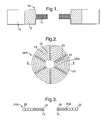
- a metal matrix wire 22 is then wound coaxially around each metal ceramic fibre 14 of the first set 20A to form an annular disc shaped preform 24A as shown in figures 2 and 3.
- Each annular, or disc shaped, preform 24A thus comprises a single metal coated 18 ceramic fibre 14 arranged in a spiral and a single metal matrix wire 22 arranged coaxially in a spiral with the metal matrix wire 22 arranged at a greater diameter than the metal coated 18 ceramic fibre 14.
- a glue 26 is applied to the annular, or disc shaped, preform 24A at suitable positions to hold the turns of the spirals together.
- Each of the metal coated ceramic fibres 14 of the second set 20B is wound around a mandrel to form an annular, or disc shaped fibre preform 24B as shown in figures 4 and 5.
- Each annular, or disc shaped, preform 24B thus comprises a single metal coated 18 ceramic fibre 14 arranged in a spiral.
- a glue 26 is applied to the annular, or disc shaped, preform 24B at suitable positions to hold the turns of the spirals together.
- the glue is selected such that it may be completely removed from the annular, or disc shaped, preforms 24A and 24B prior to consolidation.
- the glue may be for example polymethyl-methacrylate in di-chloromethane or perspex in di-chloromethane.
- a first annular ring, or metal disc, 30 is formed and an annular axially extending groove 32 is machined in one axial face 34 of the first metal ring 30, as shown in figure 8.
- the annular groove 32 has straight parallel sides, which form a rectangular cross-section.
- a second metal ring, or a metal disc, 36 is formed and an annular axially extending projection 38 is machined from the second metal ring 36 such that it extends from one axial face 40 of the second metal ring 36.
- the second metal ring 30 is also machined to form two annular grooves 42 and 44 in the face 40 of the second metal ring 36.
- the annular grooves 42 and 44 are arranged radially on opposite sides of the annular projection 38 and the annular grooves 42 and 44are tapered radially from the axial face 40 to the base of the annular projection 38. It is to be noted that the radially inner and outer dimensions, diameters, of the annular projection 38 are substantially the same as the radially inner and outer dimensions, diameters, of the annular groove 32.
- annular preforms 24A and one or more annular preforms 24B are positioned coaxially in the annular groove 32 in the axial face 34 of the first metal ring 30.
- the radially inner and outer dimensions, diameters, of the annular preforms 24A and 24B are substantially the same as the radially inner and outer dimensions, diameters, of the annular groove 32 to allow the annular preforms 24A and 24B to be loaded into the annular groove 32 while substantially filling the annular groove 32.
- a sufficient number of annular preforms 24A and 24B are stacked one upon the other in a predetermined arrangement in the annular groove 32 to partially fill the annular groove 32 to a predetermined level.
- the second metal ring 36 is then arranged such that the axial face 40 confronts the axial face 34 of the first metal ring 30 and the axes of the first and second metal rings 30 and 36 are aligned such that the annular projection 38 on the second metal ring 36 aligns with the annular groove 32 in the first metal ring 30.
- the second metal ring 36 is then pushed towards the first metal ring 30 such that the annular projection 38 enters the annular groove 32 and is further pushed until the axial face 40 of the second metal ring 36 abuts the axial face 34 of the first metal ring 30.
- the radially inner and outer peripheries of the axial face 34 of the first metal ring 30 are sealed to the radially inner and outer peripheries respectively of the axial face 40 of the second metal ring 36 to form a sealed assembly.
- the sealing is preferably by TIG welding, electron beam welding, laser welding or other suitable welding processes to form an inner annular weld seal and an outer annular weld seal.
- the sealed assembly is evacuated using a vacuum pump and pipe connected to the chambers 42 or 44.
- the sealed assembly is then heated, while being continuously evacuated to evaporate the glue from the annular preforms 24A and 24B and to remove the glue from the sealed assembly.
- the pipe is sealed.
- the sealed assembly is then heated to diffusion bonding temperature and isostatic pressure is applied to the sealed assembly, this is known as hot isostatic pressing.
- hot isostatic pressing This results in axial consolidation of the annular preforms 24A and 24B and diffusion bonding of the first metal ring 30 to the second metal ring 36 and diffusion bonding of the metal on the metal coated 18 ceramic fibres 14 to the metal on other metal coated 18 ceramic fibres 14 to the first metal ring 30, the second metal ring 36 and to the metal matrix wire 22.
- the pressure acts equally from all directions on the sealed assembly, and this causes the annular projection 38 to move axially into the annular groove 32 to consolidate the annular preforms 24A and 24B.
- the resulting consolidated and diffusion bonded ceramic fibre reinforced component 60 is shown in figure 9 and 10, which shows the ceramic fibres 14 and the diffusion bond region 62. Additionally the provision of the grooves, or chambers 42 and 44 allows the annular projection 38 to move during the consolidation process and in so doing this results in the formation of a recess 63 in the surface of what was the second metal ring. The recess 63 indicates that successful consolidation and diffusion bonding has occurred.
- the component After consolidation and diffusion bonding the component is machined to remove at least a portion of what was originally the second metal ring and at least a portion of the diffusion bonded region.
- the component may then be machined for example by electrochemical machining or milling to form the integral compressor blades or the component may be machined to form one or more slots to receive the roots of compressor blades.
- compressor blades may be friction welded, laser welded or electron beam welded onto the component.
- the length of the metal coated 18 ceramic fibres 14 and the length of the metal matrix wires 22 in the annular preforms 24A may be preselected so as to obtain fibre reinforcement at the appropriate diameters in the component. Additionally it may be possible to wind the metal matrix wire 22 around the mandrel first and then to wind the metal coated ceramic fibre 14 coaxially around the metal matrix wire 22 so as to obtain fibre reinforcement at the appropriate diameters in the component. Furthermore, it may be possible to have two or more predetermined lengths of metal coated ceramic fibre and two or more predetermined lengths of metal matrix wire sequentially wound coaxially around each other in a common plane.
- preforms 24A and 24B there are two preforms 24A between two preforms 24A to provide less ceramic fibre reinforcement in the central area at the outer diameter region as shown in figure 10.
- the preforms 24A and 24B may be stacked in any predetermined arrangement.
- the preforms 24A and 24B may be arranged alternately, as shown in figure 11, or there may a plurality of preforms 24A between adjacent preforms 24B or a plurality of preforms 24B between adjacent preforms 24A or there may a combination of any of these in the stack of preforms 24A and 24B.
- the ceramic fibre reinforced metal rotor 10 is manufactured using a plurality of metal coated ceramic fibres and a plurality of metal matrix wires.
- Each ceramic fibre 14 is coated with metal matrix 18 by any suitable method, for example physical vapour deposition, sputtering etc.
- the metal coated 18 ceramic fibres 14 are arranged to have a predetermined length.
- Each of the metal coated ceramic fibres 14 is wound around a mandrel to form an annular, or disc shaped fibre preform 24B as shown in figures 4 and 5.
- Each annular, or disc shaped, preform 24B thus comprises a single metal coated 18 ceramic fibre 14 arranged in a spiral.
- a glue 26 is applied to the annular, or disc shaped, preform 24B at suitable positions to hold the turns of the spirals together.
- the metal matrix wires 28 are arranged to have a predetermined length. Each of the metal matrix wires 28 is wound around a mandrel to form an annular, or disc shaped preform 24C as shown in figures 6 and 7. Each annular, or disc shaped, preform 24C thus comprises a single metal matrix wire 28 arranged in a spiral. A glue 26 is applied to the annular, or disc shaped, preform 24C at suitable positions to hold the turns of the spirals together.
- one or more annular preforms 24B and one or more annular preforms 24C are positioned coaxially in the annular groove 32 in the axial face 34 of the first metal ring 30, as shown in figure 12.
- the radially inner and outer dimensions, diameters, of the annular preforms 24B and 24C are substantially the same as the radially inner and outer dimensions, diameters, of the annular groove 32 to allow the annular preforms 24B and 24C to be loaded into the annular groove 32 while substantially filling the annular groove 32.
- a sufficient number of annular preforms 24B and 24C are stacked one upon the other in a predetermined arrangement in the annular groove 32 to partially fill the annular groove 32 to a predetermined level.
- the preforms 24B and 24C are arranged alternately, as shown in figure 12. However, the preforms 24B and 24C may be stacked in any predetermined arrangement. There may be a plurality of preforms 24B between adjacent preforms 24C or a plurality of preforms 24C between adjacent preforms 24B or there may a combination of any of these in the stack of preforms 24B and 24C.
- the diameter of the metal matrix wire 28 of the annular preforms 24C may the same diameter, or a different diameter to the diameter of the metal coated 18 ceramic fibres 14 of the annular preforms 24B.
- the annular preforms 24C may also comprise two or more metal matrix wires having different diameter wound together around a mandrel.
- the annular preforms 24A may also comprise one or more metal matrix fibres and one or more metal matrix wires having different diameters wound together around a mandrel.
- the reinforcing fibre may comprise alumina, silicon carbide, silicon nitride, boron, or other suitable fibre.
- the metal coating on the ceramic fibre may comprise titanium, titanium aluminide, an alloy of titanium or any other suitable metal, alloy or intermetallic which is capable of being bonded.
- the metal matrix wire may comprise titanium, titanium aluminide, an alloy of titanium or any other suitable metal, alloy or intermetallic which is capable of being bonded.
- the first metal ring and the second metal ring comprise titanium, titanium aluminide, an alloy of titanium or any other suitable metal, alloy or intermetallic which is capable of being bonded.
- the present invention has enables the ceramic fibre reinforced metal component to be produced at a lower cost by using metal matrix wires and metal coated ceramic fibres.
- the use of metal matrix wires enables the amount of metal to be deposited on the metal coated ceramic fibres to be reduced and hence reduces the cost of depositing metal onto the ceramic fibres.
- the present invention allows different metals, or alloys to be used for the metal matrix wires and the metal coating on the ceramic fibres.
- the present invention allows the radial strength of the ceramic fibre reinforced component to be improved without limiting hoop strength.
- each spirally wound metal coated ceramic fibre preform is arranged in a different, parallel, plane to the spirally wound metal matrix wire or some of the spirally wound metal coated ceramic fibre preforms are arranged in the same plane as the spirally wound metal matrix wire.
Landscapes
- Chemical & Material Sciences (AREA)
- Engineering & Computer Science (AREA)
- Materials Engineering (AREA)
- Mechanical Engineering (AREA)
- Metallurgy (AREA)
- Organic Chemistry (AREA)
- Crystallography & Structural Chemistry (AREA)
- Manufacture Of Alloys Or Alloy Compounds (AREA)
Abstract
Description
arranging the second metallic member such that the circumferentially extending projection of the second metallic member is aligned with the circumferentially extending groove of the first metallic member, applying heat and pressure such that the circumferentially extending projection moves into the circumferentially extending groove to consolidate the at least one circumferentially extending metal coated fibre and the circumferentially extending metallic wire and to bond the first metallic member, the second metallic member, the at least one circumferentially extending metal coated fibre and the circumferentially extending metallic wire to form a unitary composite component.
Claims (15)
- A method of manufacturing a fibre reinforced metal component (10) comprising the steps of:-(a) forming a longitudinally extending groove (32) in a face (34) of a first metallic member (30),(b) arranging at least one longitudinally extending metal coated (18) fibre (14) and at least one longitudinally extending metallic wire (22) in the longitudinally extending groove (32) in the first metallic member (30),(c) forming a longitudinally extending projection (38) on a face (40) of a second metallic member (36),(d) arranging the second metallic member (36) such that the longitudinally extending projection (38) of the second metallic member (36) is aligned with the longitudinally extending groove (32) of the first metallic member (30),(e) applying heat and pressure such that the longitudinally extending projection (38) moves into the longitudinally extending groove (32) to consolidate the at least one longitudinally extending metal coated (18) fibre (14) and the at least one longitudinally extending metallic wire (22) and to bond the first metallic member (30), the second metallic member (36), the at least one longitudinally extending metal coated (18) fibre (14) and the at least one longitudinally extending metallic wire (22) to form a unitary composite component (10).
- A method as claimed in claim 1 comprising forming a circumferentially extending groove (32) in an axial face (34) of the first metallic member (30), arranging the at least one circumferentially extending metal coated (18) fibre (14) and at least one circumferentially extending metallic wire (22) in the circumferentially extending groove (32) in the first metallic member (30), forming a circumferentially extending projection (38) on a face (40) of the second metallic member (36), arranging the second metallic member (36) such that the circumferentially extending projection (38) of the second metallic member (36) is aligned with the circumferentially extending groove (32) of the first metallic member (30), applying heat and pressure such that the circumferentially extending projection (38) moves into the circumferentially extending groove (32) to consolidate the at least one circumferentially extending metal coated (18) fibre (14) and the circumferentially extending metallic wire (22) and to bond the first metallic member (30), the second metallic member (36), the at least one circumferentially extending metal coated (18) fibre (14) and the circumferentially extending metallic wire (22) to form a unitary composite component (10).
- A method as claimed in claim 2 comprising arranging the at least one circumferentially extending metal coated (18) fibre (14) and the at least one circumferentially extending metallic wire (22) in the circumferentially extending groove (32) in the first metallic member (30) such that the at least one circumferentially extending metal coated (18) fibre (14) and the at least one circumferentially extending metallic wire (22) are arranged in a common plane.
- A method as claimed in claim 3 comprising arranging the at least one circumferentially extending metallic wire (22) at a greater radial distance than the at least one circumferentially extending metal coated (18) fibre (14).
- A method as claimed in claim 2 comprising arranging the at least one circumferentially extending metal coated (18) fibre (14) and the at least one circumferentially extending metallic wire (22) in the circumferentially extending groove (32) in the first metallic member (30) such that the at least one circumferentially extending metal coated (18) fibre (14) and the at least one circumferentially extending metallic wire (22) are arranged in different planes.
- A method as claimed in any of claims 2 to 5 comprising arranging a plurality of circumferentially extending metal coated (18) fibres (14) and a plurality of circumferentially extending metallic wires (22) in the circumferentially extending groove (32) in the first metallic member (30).
- A method as claimed in claim 6 comprising arranging the plurality of circumferentially extending metal coated (18) fibres (14) and the plurality of circumferentially extending metallic wires (22) in the circumferentially extending groove (32) in the first metallic member (30) such that a first one of the plurality of circumferentially extending metal coated (18) fibres (14) and a first one of the plurality of circumferentially extending metallic wires (22) are arranged in a first common plane, a second one of the plurality of circumferentially extending metal coated (18) fibres (14) and a second one of the plurality of circumferentially extending metallic wires (22) are arranged in a second common plane and the first and second common planes are spaced apart axially of the first metallic member (30).
- A method as claimed in claim 7 comprising arranging a third one of the plurality of circumferentially extending metallic wires (22) in a third plane, and the third plane is arranged axially between the first and second common planes.
- A method as claimed in claim 1 wherein the at least one metallic coated (18) fibre (14) is selected from the group comprising a titanium coated fibre, a titanium aluminide coated fibre and a titanium alloy coated fibre.
- A method as claimed in claim 1 wherein the at least one metallic wire (22) is selected from the group comprising a titanium wire, titanium aluminide wire and a titanium alloy wire.
- A method as claimed in claim 1 wherein the metal of the at least one metallic coated (18) fibre (14) is a different metal to the metal of the at least one metallic wire (22).
- A method as claimed in claim 1 wherein the diameter of the at least one metallic coated (18) fibre (14) is different to the diameter of the at least one metallic fibre (22).
- A method as claimed in claim 1 wherein the diameter of the at least one metallic coated (18) fibre (14) is the same as the diameter of the at least one metallic wire (22).
- A method as claimed in claim 2 wherein the at least one circumferentially extending metal coated (18) fibre (14) is arranged in a spiral.
- A method as claimed in claim 2 wherein the at least one circumferentially extending metallic wire (22) is arranged in a spiral.
Applications Claiming Priority (2)
| Application Number | Priority Date | Filing Date | Title |
|---|---|---|---|
| GB0119636 | 2001-08-11 | ||
| GBGB0119636.9A GB0119636D0 (en) | 2001-08-11 | 2001-08-11 | a method of manufacturing a fibre reinforced metal component |
Publications (3)
| Publication Number | Publication Date |
|---|---|
| EP1288324A2 true EP1288324A2 (en) | 2003-03-05 |
| EP1288324A3 EP1288324A3 (en) | 2003-05-02 |
| EP1288324B1 EP1288324B1 (en) | 2005-03-30 |
Family
ID=9920243
Family Applications (1)
| Application Number | Title | Priority Date | Filing Date |
|---|---|---|---|
| EP02255206A Expired - Lifetime EP1288324B1 (en) | 2001-08-11 | 2002-07-25 | A method of manufacturing a fibre reinforced metal component |
Country Status (4)
| Country | Link |
|---|---|
| US (1) | US6786389B2 (en) |
| EP (1) | EP1288324B1 (en) |
| DE (1) | DE60203453T2 (en) |
| GB (1) | GB0119636D0 (en) |
Cited By (3)
| Publication number | Priority date | Publication date | Assignee | Title |
|---|---|---|---|---|
| EP1527842A1 (en) * | 2003-10-24 | 2005-05-04 | ROLLS-ROYCE plc | A method of manufacturing a fibre reinforced metal matrix composite article |
| EP1533067A1 (en) * | 2003-11-20 | 2005-05-25 | Rolls-Royce Plc | A method of manufacturing a fibre reinforced metal matrix composite article |
| WO2012123686A1 (en) * | 2011-03-15 | 2012-09-20 | Snecma | Process for manufacturing a one-piece axisymmetric metallic part from composite fibrous structures |
Families Citing this family (10)
| Publication number | Priority date | Publication date | Assignee | Title |
|---|---|---|---|---|
| JP3848319B2 (en) * | 2003-11-11 | 2006-11-22 | キヤノン株式会社 | Information processing method and information processing apparatus |
| GB0327043D0 (en) * | 2003-11-18 | 2004-04-07 | Rolls Royce Plc | A method of manufacturing an article by applying heat and pressure, a method of connecting a pipe to a sealed assembly and a connector for use therein |
| FR2933422B1 (en) * | 2008-07-04 | 2011-05-13 | Messier Dowty Sa | METHOD FOR MANUFACTURING A METAL PIECE COMPRISING INTERNAL REINFORCEMENTS FORMED OF CERAMIC FIBERS |
| FR2970266B1 (en) * | 2011-01-10 | 2013-12-06 | Snecma | METHOD FOR MANUFACTURING A MONOBLOC ANNULAR METAL PIECE WITH A REINFORCING INSERT IN COMPOSITE MATERIAL, AND PART OBTAINED |
| FR2972123B1 (en) | 2011-03-02 | 2014-06-13 | Snecma | PROCESS FOR MANUFACTURING A MONOBLOC REVOLUTION METAL PIECE INCORPORATING A CERAMIC FIBER REINFORCEMENT |
| GB2510562B (en) | 2013-02-06 | 2015-02-25 | Rolls Royce Plc | Method of forming a bonded assembly |
| EP2796230A1 (en) * | 2013-04-22 | 2014-10-29 | Gervaux Ltd | Method of manufacturing a metallic component by use of wire winding and hot isostatic pressing |
| EP3120033B1 (en) | 2014-03-19 | 2022-04-13 | Penn Engineering & Manufacturing Corp. | Stabilized panel fastener |
| MX2018013251A (en) * | 2016-07-07 | 2019-02-21 | Bull Moose Tube Company | Steel coated metal structures and methods of fabricating the same. |
| CN118581364A (en) * | 2024-05-14 | 2024-09-03 | 哈尔滨工业大学 | SiCw directional arrangement Brigan structure preform and aluminum-based composite material based thereon and preparation method and application thereof |
Family Cites Families (11)
| Publication number | Priority date | Publication date | Assignee | Title |
|---|---|---|---|---|
| US4448838A (en) * | 1981-09-04 | 1984-05-15 | Lear Fan Corp. | Graphite fiber reinforced laminate structure capable of withstanding lightning strikes |
| US4697324A (en) | 1984-12-06 | 1987-10-06 | Avco Corporation | Filamentary structural module for composites |
| US4782992A (en) | 1986-11-21 | 1988-11-08 | Textron Inc. | Method of forming articles |
| US5132278A (en) * | 1990-05-11 | 1992-07-21 | Advanced Technology Materials, Inc. | Superconducting composite article, and method of making the same |
| US5337940A (en) | 1990-12-11 | 1994-08-16 | Woods Harlan L | Composite preform and method of manufacturing fiber reinforced composite |
| US5260124A (en) * | 1991-11-25 | 1993-11-09 | The United States Of America As Represented By The Administrator Of The National Aeronautics And Space Administration | Intercalated hybrid graphite fiber composite |
| US5412748A (en) * | 1992-12-04 | 1995-05-02 | Kabushiki Kaisha Toshiba | Optical semiconductor module |
| JPH07249798A (en) * | 1994-03-09 | 1995-09-26 | Fujitsu Ltd | Optical component fixing device and manufacturing method thereof |
| GB9619890D0 (en) * | 1996-09-24 | 1996-11-06 | Rolls Royce Plc | A method of making a fibre reinforced metal component |
| WO2000065115A2 (en) * | 1999-04-28 | 2000-11-02 | Allison Engine Company, Inc. | Fiber reinforced composite material system |
| JP2002169067A (en) * | 2000-11-29 | 2002-06-14 | Fujikura Ltd | Optical composite overhead cable |
-
2001
- 2001-08-11 GB GBGB0119636.9A patent/GB0119636D0/en not_active Ceased
-
2002
- 2002-07-25 DE DE60203453T patent/DE60203453T2/en not_active Expired - Lifetime
- 2002-07-25 EP EP02255206A patent/EP1288324B1/en not_active Expired - Lifetime
- 2002-07-29 US US10/206,768 patent/US6786389B2/en not_active Expired - Lifetime
Cited By (10)
| Publication number | Priority date | Publication date | Assignee | Title |
|---|---|---|---|---|
| EP1527842A1 (en) * | 2003-10-24 | 2005-05-04 | ROLLS-ROYCE plc | A method of manufacturing a fibre reinforced metal matrix composite article |
| US7343677B2 (en) | 2003-10-24 | 2008-03-18 | Rolls-Royce Plc | Method of manufacturing a fiber reinforced metal matrix composite article |
| EP1533067A1 (en) * | 2003-11-20 | 2005-05-25 | Rolls-Royce Plc | A method of manufacturing a fibre reinforced metal matrix composite article |
| US7516548B2 (en) | 2003-11-20 | 2009-04-14 | Rolls-Royce Plc | Method of manufacturing a fibre reinforced metal matrix composite article |
| WO2012123686A1 (en) * | 2011-03-15 | 2012-09-20 | Snecma | Process for manufacturing a one-piece axisymmetric metallic part from composite fibrous structures |
| FR2972661A1 (en) * | 2011-03-15 | 2012-09-21 | Snecma | PROCESS FOR MANUFACTURING A MONOBLOC REVOLUTION METAL PART FROM COMPOSITE FIBROUS STRUCTURES |
| CN103459067A (en) * | 2011-03-15 | 2013-12-18 | 斯奈克玛 | Process for manufacturing a one-piece axisymmetric metallic part from composite fibrous structures |
| US9321106B2 (en) | 2011-03-15 | 2016-04-26 | Snecma | Process for manufacturing a one-piece axisymmetric metallic part from composite fibrous structures |
| RU2584106C2 (en) * | 2011-03-15 | 2016-05-20 | Снекма | Method of producing metallic single-piece rotation part based on composite fibrous structures |
| CN103459067B (en) * | 2011-03-15 | 2016-10-12 | 斯奈克玛 | For the method manufacturing the axisymmetric metal parts of monoblock type from complex structure of filament |
Also Published As
| Publication number | Publication date |
|---|---|
| DE60203453T2 (en) | 2005-08-18 |
| DE60203453D1 (en) | 2005-05-04 |
| US6786389B2 (en) | 2004-09-07 |
| EP1288324B1 (en) | 2005-03-30 |
| US20030029904A1 (en) | 2003-02-13 |
| GB0119636D0 (en) | 2001-10-03 |
| EP1288324A3 (en) | 2003-05-02 |
Similar Documents
| Publication | Publication Date | Title |
|---|---|---|
| US5946801A (en) | Method of making a fibre reinforced metal component | |
| US7543379B2 (en) | Method of manufacturing an article by applying heat and pressure, a method of connecting a pipe to a sealed assembly and a connector for use therein | |
| EP2418297B1 (en) | A method of manufacturing a fibre reinforced metal matrix composite article | |
| EP1533067B1 (en) | A method of manufacturing a fibre reinforced metal matrix composite article | |
| EP1288324B1 (en) | A method of manufacturing a fibre reinforced metal component | |
| US5222296A (en) | Method of making a fibre reinforced metal component | |
| JP4804740B2 (en) | Method for producing a fiber reinforced matrix composite product and cassette used in the method | |
| EP1527842B1 (en) | A method of manufacturing a fibre reinforced metal matrix composite article | |
| US5305520A (en) | Method of making fibre reinforced metal component | |
| US8065799B2 (en) | Method of fabricating a turbomachine rotor disk | |
| GB2198675A (en) | Method of forming diffusion bonded filament-reinforced articles | |
| CA2325212C (en) | Method of producing an element of composite material | |
| US20060024466A1 (en) | Wire/fiber ring and method for manufacturing the same | |
| GB2196566A (en) | Producing reinforced articles |
Legal Events
| Date | Code | Title | Description |
|---|---|---|---|
| PUAI | Public reference made under article 153(3) epc to a published international application that has entered the european phase |
Free format text: ORIGINAL CODE: 0009012 |
|
| AK | Designated contracting states |
Kind code of ref document: A2 Designated state(s): AT BE BG CH CY CZ DE DK EE ES FI FR GB GR IE IT LI LU MC NL PT SE SK TR |
|
| AX | Request for extension of the european patent |
Extension state: AL LT LV MK RO SI |
|
| PUAL | Search report despatched |
Free format text: ORIGINAL CODE: 0009013 |
|
| AK | Designated contracting states |
Designated state(s): AT BE BG CH CY CZ DE DK EE ES FI FR GB GR IE IT LI LU MC NL PT SE SK TR |
|
| AX | Request for extension of the european patent |
Extension state: AL LT LV MK RO SI |
|
| RIC1 | Information provided on ipc code assigned before grant |
Ipc: 7C 22C 47/00 B Ipc: 7C 22C 47/06 B Ipc: 7C 22C 47/20 A |
|
| 17P | Request for examination filed |
Effective date: 20030519 |
|
| AKX | Designation fees paid |
Designated state(s): DE FR GB |
|
| 17Q | First examination report despatched |
Effective date: 20040330 |
|
| GRAP | Despatch of communication of intention to grant a patent |
Free format text: ORIGINAL CODE: EPIDOSNIGR1 |
|
| GRAS | Grant fee paid |
Free format text: ORIGINAL CODE: EPIDOSNIGR3 |
|
| GRAA | (expected) grant |
Free format text: ORIGINAL CODE: 0009210 |
|
| AK | Designated contracting states |
Kind code of ref document: B1 Designated state(s): DE FR GB |
|
| REG | Reference to a national code |
Ref country code: GB Ref legal event code: FG4D |
|
| REF | Corresponds to: |
Ref document number: 60203453 Country of ref document: DE Date of ref document: 20050504 Kind code of ref document: P |
|
| REG | Reference to a national code |
Ref country code: IE Ref legal event code: FG4D |
|
| PLBE | No opposition filed within time limit |
Free format text: ORIGINAL CODE: 0009261 |
|
| STAA | Information on the status of an ep patent application or granted ep patent |
Free format text: STATUS: NO OPPOSITION FILED WITHIN TIME LIMIT |
|
| ET | Fr: translation filed | ||
| 26N | No opposition filed |
Effective date: 20060102 |
|
| REG | Reference to a national code |
Ref country code: FR Ref legal event code: PLFP Year of fee payment: 14 |
|
| REG | Reference to a national code |
Ref country code: FR Ref legal event code: PLFP Year of fee payment: 15 |
|
| REG | Reference to a national code |
Ref country code: FR Ref legal event code: PLFP Year of fee payment: 16 |
|
| REG | Reference to a national code |
Ref country code: FR Ref legal event code: PLFP Year of fee payment: 17 |
|
| PGFP | Annual fee paid to national office [announced via postgrant information from national office to epo] |
Ref country code: DE Payment date: 20180727 Year of fee payment: 17 Ref country code: FR Payment date: 20180726 Year of fee payment: 17 |
|
| PGFP | Annual fee paid to national office [announced via postgrant information from national office to epo] |
Ref country code: GB Payment date: 20180727 Year of fee payment: 17 |
|
| REG | Reference to a national code |
Ref country code: DE Ref legal event code: R119 Ref document number: 60203453 Country of ref document: DE |
|
| GBPC | Gb: european patent ceased through non-payment of renewal fee |
Effective date: 20190725 |
|
| PG25 | Lapsed in a contracting state [announced via postgrant information from national office to epo] |
Ref country code: GB Free format text: LAPSE BECAUSE OF NON-PAYMENT OF DUE FEES Effective date: 20190725 Ref country code: DE Free format text: LAPSE BECAUSE OF NON-PAYMENT OF DUE FEES Effective date: 20200201 |
|
| PG25 | Lapsed in a contracting state [announced via postgrant information from national office to epo] |
Ref country code: FR Free format text: LAPSE BECAUSE OF NON-PAYMENT OF DUE FEES Effective date: 20190731 |