EP1288148A1 - Method and device for aligning sheets along a single edge - Google Patents
Method and device for aligning sheets along a single edge Download PDFInfo
- Publication number
- EP1288148A1 EP1288148A1 EP01000417A EP01000417A EP1288148A1 EP 1288148 A1 EP1288148 A1 EP 1288148A1 EP 01000417 A EP01000417 A EP 01000417A EP 01000417 A EP01000417 A EP 01000417A EP 1288148 A1 EP1288148 A1 EP 1288148A1
- Authority
- EP
- European Patent Office
- Prior art keywords
- sheet
- supporting
- alignment
- aligned position
- stop
- Prior art date
- Legal status (The legal status is an assumption and is not a legal conclusion. Google has not performed a legal analysis and makes no representation as to the accuracy of the status listed.)
- Granted
Links
Images


Classifications
-
- B—PERFORMING OPERATIONS; TRANSPORTING
- B65—CONVEYING; PACKING; STORING; HANDLING THIN OR FILAMENTARY MATERIAL
- B65H—HANDLING THIN OR FILAMENTARY MATERIAL, e.g. SHEETS, WEBS, CABLES
- B65H1/00—Supports or magazines for piles from which articles are to be separated
- B65H1/02—Supports or magazines for piles from which articles are to be separated adapted to support articles on edge
- B65H1/025—Supports or magazines for piles from which articles are to be separated adapted to support articles on edge with controlled positively-acting mechanical devices for advancing the pile to present the articles to the separating device
-
- B—PERFORMING OPERATIONS; TRANSPORTING
- B65—CONVEYING; PACKING; STORING; HANDLING THIN OR FILAMENTARY MATERIAL
- B65H—HANDLING THIN OR FILAMENTARY MATERIAL, e.g. SHEETS, WEBS, CABLES
- B65H9/00—Registering, e.g. orientating, articles; Devices therefor
- B65H9/002—Registering, e.g. orientating, articles; Devices therefor changing orientation of sheet by only controlling movement of the forwarding means, i.e. without the use of stop or register wall
-
- B—PERFORMING OPERATIONS; TRANSPORTING
- B65—CONVEYING; PACKING; STORING; HANDLING THIN OR FILAMENTARY MATERIAL
- B65H—HANDLING THIN OR FILAMENTARY MATERIAL, e.g. SHEETS, WEBS, CABLES
- B65H9/00—Registering, e.g. orientating, articles; Devices therefor
- B65H9/10—Pusher and like movable registers; Pusher or gripper devices which move articles into registered position
- B65H9/103—Pusher and like movable registers; Pusher or gripper devices which move articles into registered position acting by friction or suction on the article for pushing or pulling it into registered position, e.g. against a stop
-
- B—PERFORMING OPERATIONS; TRANSPORTING
- B65—CONVEYING; PACKING; STORING; HANDLING THIN OR FILAMENTARY MATERIAL
- B65H—HANDLING THIN OR FILAMENTARY MATERIAL, e.g. SHEETS, WEBS, CABLES
- B65H2301/00—Handling processes for sheets or webs
- B65H2301/30—Orientation, displacement, position of the handled material
- B65H2301/32—Orientation of handled material
- B65H2301/321—Standing on edge
-
- B—PERFORMING OPERATIONS; TRANSPORTING
- B65—CONVEYING; PACKING; STORING; HANDLING THIN OR FILAMENTARY MATERIAL
- B65H—HANDLING THIN OR FILAMENTARY MATERIAL, e.g. SHEETS, WEBS, CABLES
- B65H2301/00—Handling processes for sheets or webs
- B65H2301/30—Orientation, displacement, position of the handled material
- B65H2301/33—Modifying, selecting, changing orientation
- B65H2301/331—Skewing, correcting skew, i.e. changing slightly orientation of material
Definitions
- the present invention relates to a method and a device for aligning sheets. More specifically the invention relates to a method and a device for aligning thermal-sensitive sheets to be used in a thermal printer.
- Thermal imaging or thermography is a recording process wherein images are generated by the use of thermal energy.
- thermography three approaches are known:
- Thermographic materials of type 1 can be rendered photothermographic by incorporating a photosensitive agent which after exposure to UV, visible or IR light, e.g. by means of a laser, is capable of catalyzing or participating in a thermographic process bringing about changes in color or optical density.
- Common thermal printers that do no use a laser light source comprise a rotatable drum and an elongate thermal head which is spring-biased towards the drum to firmly line-wise contact a heat-sensitive material which is passed between the head and the drum.
- the thermal head includes a plurality of heating elements. The image-wise heating of a sheet is performed on a line by line basis, with the heating elements geometrically juxtaposed along each other in a bead like row running parallel to the axis of the drum. Each of these elements is capable of being energized by heating pulses, the energy of which is controlled in accordance with the required density of the corresponding picture element.
- the sheet is advanced between the head and the drum by frictional contact of its rear side with the drum.
- Patent application EP-A-0 846 565 discloses such a thermal printer having a thermal head.
- Fig. 1 shows two sheets 10 that bear images that are printed by a thermal printer having a thermal head.
- the image areas E are substantially black and the margins A, B, C and D are transparent. The image cannot be printed on the sheet up to the edge since otherwise the thermal sensitive layer of the sheet would be squeezed at the edge due to the pressure between head and drum, which would soil the thermal head and the transport rollers.
- the images are viewed on a light box for diagnosis.
- the images can be positioned so that the transparent margins B are outside of the illuminated area while black screens can be moved in the light box, like curtains, so that they cover the margins C and D.
- black screens can be moved in the light box, like curtains, so that they cover the margins C and D.
- a transparent area between the two image areas E remains.
- Fig. 1 shows two mammographic images.
- mammography it is customary to view the images of the right and of the left breast on a light box, positioned with respect to each other as shown in Fig. 1 (reference sign 15 in Fig. 1 indicates the contours of the breasts).
- Both sheets 10 are pushed against each other so that no space is left between them (for clarity, in Fig. 1 an open space is shown between the sheets 10).
- a transparent area of twice margin A remains between the images.
- such mammographic images did not have a transparent margin, because they were made e.g. by a conventional AgX apparatus or in a photothermographic printer wherein the laser can expose the sheet up to its edges.
- a sheet 10 having a substantially straight edge 11, as shown in Fig. 1, is accurately aligned in accordance with the invention.
- An image can then be printed on the sheet leaving only a small margin A, of e.g. 1.1 mm, between the image area E and the substantially straight edge 11.
- a transparent area of twice such a small margin A, between two image areas E, is not disturbing when viewed on a light box.
- the margin A has a nearly constant width so that there is no risk of the image area E coming too close to the sheet edge 11, which would result in soiling the thermal head as mentioned above.
- One margin, margin A in Fig. 1 has a small width; the other margins, margins B, C and D in Fig. 1, may have a larger width,
- the substantially straight edge 11 of sheet 10 is aligned with respect to an alignment axis 25 that is substantially perpendicular to the axis 45 of the drum of the thermal printer.
- Sheet 10 as shown in Fig. 1 may be a substantially rectangular sheet having the standard dimensions of 10" x 12".
- the image is then printed line-wise with the image lines substantially perpendicular to edge 11, i.e. substantially parallel to edge 12.
- edge 12 is the short, 10"
- sheet edge and edge 11 is the long, 12", sheet edge.
- LS is the straight line segment that is the least squares fit of the edge.
- An edge is substantially straight if, for all points PT in line segments S belonging to the edge, so that the total length of the line segments S is at least 80 % of the length of the edge and preferably at least 90 % of the length of the edge, the distance d between PT and LS is d ⁇ 5 mm, preferably d ⁇ 3 mm, more preferably d ⁇ 1 mm and most preferably d ⁇ 0.5 mm.
- the distance between points PT and straight least squares segment LS may be larger over portions of the edge (of relative length 20 % or 10 %) to allow for e.g. notches which are quite customary in medical film sheets.
- a first line L1 is "substantially parallel" to a second line L2 if, when L1* is the line parallel to L1 through an arbitrary point O taken as origin and L2* is the line parallel to L2 through O, the smallest angle ⁇ between L1* and L2* is ⁇ ⁇ 15°, preferably ⁇ ⁇ 10°, more preferably ⁇ ⁇ 5°.
- a first line L1 is "substantially perpendicular" to a second line L2 if, when L1* is the line parallel to L1 through an arbitrary point O taken as origin and L2* is the line parallel to L2 through O, the smallest angle ⁇ between L1* and L2* is ⁇ > 75°, preferably ⁇ > 80°, more preferably ⁇ > 85°.
- a line is "substantially vertical” if it is substantially parallel to a vertical line; a vertical line has the same direction as the force of gravity.
- a "substantially horizontal" line is substantially perpendicular to a vertical line.
- a sheet is "substantially rectangular” if it has four substantially straight edges and if the adjoining edges are substantially perpendicular to each other, as defined above.
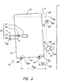
- Fig. 2 shows a first embodiment of a device according to the present invention.
- a sheet 10 which may be fed from a sheet tray in a thermal printer, is dropped onto two supporting stops 27 and 28.
- the sheet is now in a first, non-aligned position, which is shown in Fig. 2.
- To accurately align sheet 10 it is moved from this first non-aligned position to a second aligned position (not shown) wherein the substantially straight edge 11 of sheet 10 contacts two alignment stops 21, 22.
- sheet 10 contacts the alignment stops 21, 22 in points Q 1 and Q 2 . These two points define an alignment axis 25.
- sheet 10 is thus aligned with its substantially straight edge 11 with respect to alignment axis 25.
- sheet 10 In order to obtain an accurately defined position of the aligned sheet 10, only one of the two supporting stops 27, 28 supports sheet 10 in its second aligned position.
- sheet 10 contacts in its second aligned position the first and second alignment stops 21, 22 and the first supporting stop 27; it does not contact the second supporting stop 28.
- sheet 10 makes contact with contact element 34 which pushes sheet 10 against the alignment stops 21, 22.
- Sheet 10 as shown in Fig. 2 is substantially rectangular.
- alignment axis 25 is substantially vertical.
- the first supporting stop 27 is positioned higher than the second supporting stop 28, i.e. y 27 > y 28 wherein y 27 and y 28 are the coordinates with respect to vertical axis y of respectively the first alignment stop 27 and the second alignment stop 28. In this way, when sheet 10 contacts the alignment stops 21 and 22, it does not contact the second supporting stop 28.
- the first supporting stop 27, which supports sheet 10 in its second aligned position is nearer the alignment axis 25 than the second supporting stop 28, i.e. in Fig. 2 distance d 27 ⁇ d 28 . In this way, the second aligned position is more stable than if d 27 > d 28 .
- Fig. 3 shows another embodiment in accordance with the invention. Contrary to the embodiment shown in Fig. 2, in the embodiment of Fig. 3 the supporting stops 27 and 28 each contact a different edge of sheet 10 in its first non-aligned position: the first supporting stop 27 contacts edge 14 while the second supporting stop 28 contacts edge 13.
- Sheet 10 is moved to its second aligned position by moving means 30.
- moving means 30 is shown schematically in Fig. 2; it comprises an electromagnet 31, a resilient element 32 such as a spring, a lever 33 that can pivot around point P and a contact element 34 on lever 33.
- electromagnet 31 is energized and pulls lever 33, and contact element 34 on lever 33, in the direction of arrow R.
- Contact element 34 contacts edge 13 of sheet 10 and pushes sheet 10 against alignment stops 21 and 22.
- Lever 33 is used to increase the stroke of electromagnet 31.
- An advantage of resilient element 32 is that a given force is applied to edge 13 without enforcing edge 13 to move over a fixed displacement, which would be the case if the resilient element 32 would be omitted.
- sheet 10 is given a slight touch.
- This touch may be given by moving means 30.
- the purpose of this touch is to obtain a good first non-aligned position of sheet 10, since dropping sheet 10 may e.g. have caused the sheet to be not well supported by the supporting stops 27, 28.
- touching the sheet is accomplished by shortly energizing the electromagnet 31 just before the electromagnet 31 is energized again to move the sheet.
- the complete cycle of touching and moving sheet 10 may be quite short, e.g. less than 1 second.
- At least one of the alignment stops 21, 22 is adjustable.
- alignment stop 21 is adjustable.
- Point Q 1 is the contact point of alignment stop 21 with sheet 10 in its second aligned position. By rotating alignment stop 21 around its pivot point 24, contact point Q 1 moves towards or away from pivot point 24, since arc 23 on which Q 1 is located is positioned eccentrically with respect to pivot point 24.
- first and second alignment stops 21, 22 are both part of a single element that contacts sheet 10 in its second aligned position by means of these first and second alignment stops 21, 22.
- Advantages of a device in accordance with the invention are that it is simple and inexpensive, yet it allows accurate sheet alignment.
- an image may be printed on the sheet in a thermal printer having a thermal head. It is preferred, as shown in Fig. 2, that the drum axis 45 of the thermal printer is substantially perpendicular to the alignment axis 25.
- Printing may proceed as follows. The aligned sheet is seized by a transport mechanism in the thermal printer - the transport system may include the thermal head and the drum. Moving means 30 is now switched off; i.e. in the embodiment of Fig. 2 electromagnet 31 is de-energized so that contact element 34 is withdrawn from sheet 10. The image is printed line-wise, while sheet 10 is advanced between the thermal head and the drum. In the embodiment shown in Fig. 2, the image lines are substantially parallel to edge 12 of sheet 10 (after alignment).
- the image is printed with a small and nearly constant margin that is adjacent to substantially straight edge 11.
- y represents a vertical axis
- the alignment axis 25 is substantially vertical and the drum axis 45 is substantially horizontal.
- a special test image may be written, preferably in the factory during production of the thermal printer. Using measurements of this test image, the alignment device is then adjusted, e.g. by adjusting alignment stop 21 in Fig. 2. In this way, the small margin of the sheet - i.e. margin A in Fig. 1 - will have a nearly constant width. To set the magnitude of the margin width, the position of the thermal head along its axis may be adjusted (the axis of the thermal head is substantially parallel to the drum axis 45).
- An aligning device as shown in Fig. 2 is used with the following coordinates with respect to axis y:
Landscapes
- Engineering & Computer Science (AREA)
- Mechanical Engineering (AREA)
- Registering Or Overturning Sheets (AREA)
- Electronic Switches (AREA)
- Handling Of Sheets (AREA)
- Discharge By Other Means (AREA)
Abstract
Description
- The present invention relates to a method and a device for aligning sheets. More specifically the invention relates to a method and a device for aligning thermal-sensitive sheets to be used in a thermal printer.
- Thermal imaging or thermography is a recording process wherein images are generated by the use of thermal energy.
- In thermography three approaches are known:
- 1. Direct thermal formation of a visible image pattern by image-wise heating of a recording material containing matter that by chemical or physical process changes color or optical density.
- 2. Image-wise transfer of an ingredient necessary for the chemical or physical process bringing about changes in color or optical density to a receptor element containing other of the ingredients necessary for said chemical or physical process followed by uniform heating to bring about said changes in color or optical density.
- 3. Thermal dye transfer printing wherein a visible image pattern is formed by transfer of a colored species from an image-wise heated donor element onto a receptor element.
-
- Thermographic materials of type 1 can be rendered photothermographic by incorporating a photosensitive agent which after exposure to UV, visible or IR light, e.g. by means of a laser, is capable of catalyzing or participating in a thermographic process bringing about changes in color or optical density.
- A survey of direct thermal imaging methods is given in the book "Imaging systems" by Kurt I. Jacobson-Ralph E. Jacobson, The Focal Press - London and New York (1976), Chapter VII under the heading "7.1 Thermography".
- Common thermal printers that do no use a laser light source comprise a rotatable drum and an elongate thermal head which is spring-biased towards the drum to firmly line-wise contact a heat-sensitive material which is passed between the head and the drum. The thermal head includes a plurality of heating elements. The image-wise heating of a sheet is performed on a line by line basis, with the heating elements geometrically juxtaposed along each other in a bead like row running parallel to the axis of the drum. Each of these elements is capable of being energized by heating pulses, the energy of which is controlled in accordance with the required density of the corresponding picture element. The sheet is advanced between the head and the drum by frictional contact of its rear side with the drum.
- Patent application EP-A-0 846 565 discloses such a thermal printer having a thermal head.
- The images that are printed on such a thermal printer are often used for diagnostic purposes, medical diagnosis in particular. Customarily such images for medical diagnosis are printed on a transparent support. Examples of such images are echograms, CT scans, NMR images. These images are negative-type images, which means that their background is substantially black, the image details having lesser optical densities. Fig. 1 shows two
sheets 10 that bear images that are printed by a thermal printer having a thermal head. The image areas E are substantially black and the margins A, B, C and D are transparent. The image cannot be printed on the sheet up to the edge since otherwise the thermal sensitive layer of the sheet would be squeezed at the edge due to the pressure between head and drum, which would soil the thermal head and the transport rollers. - These images are viewed on a light box for diagnosis. On the light box, the images can be positioned so that the transparent margins B are outside of the illuminated area while black screens can be moved in the light box, like curtains, so that they cover the margins C and D. However, if two
sheets 10 are positioned alongside each other, as shown in Fig. 1, a transparent area between the two image areas E remains. - Radiologists are unfamiliar with such a transparent area, which does not exist in conventional AgX X-ray images. Moreover, a large transparent area has a dazzling effect. Fig. 1 shows two mammographic images. In mammography, it is customary to view the images of the right and of the left breast on a light box, positioned with respect to each other as shown in Fig. 1 (
reference sign 15 in Fig. 1 indicates the contours of the breasts). Bothsheets 10 are pushed against each other so that no space is left between them (for clarity, in Fig. 1 an open space is shown between the sheets 10). Thus, a transparent area of twice margin A remains between the images. Up till now, such mammographic images did not have a transparent margin, because they were made e.g. by a conventional AgX apparatus or in a photothermographic printer wherein the laser can expose the sheet up to its edges. - It would be advantageous to print such mammographic images by means of a printer with a thermal head, since this is less expensive than using a photothermographic printer. However, when printed by a conventional printer with a thermal head, on a light box the transparent area between the two images is disturbing.
- It is therefore an object of the invention to provide a thermal printer having a thermal head that can print mammographic images that are suitable for diagnosis on a light box.
- It is a further object of the invention to provide a method that allows obtaining, by means of a thermal printer having a thermal head, mammographic images that are suitable for diagnosis on a light box.
- The above-mentioned objects are realised by a thermal printer including a device as claimed in claim 1 and by a thermal printer performing a method as claimed in claim 8. The dependent claims set out preferred embodiments of the invention.
- A
sheet 10 having a substantiallystraight edge 11, as shown in Fig. 1, is accurately aligned in accordance with the invention. An image can then be printed on the sheet leaving only a small margin A, of e.g. 1.1 mm, between the image area E and the substantiallystraight edge 11. A transparent area of twice such a small margin A, between two image areas E, is not disturbing when viewed on a light box. Because of the accurate alignment, the margin A has a nearly constant width so that there is no risk of the image area E coming too close to thesheet edge 11, which would result in soiling the thermal head as mentioned above. One margin, margin A in Fig. 1, has a small width; the other margins, margins B, C and D in Fig. 1, may have a larger width, - In a preferred embodiment of the invention, shown in Fig. 2, the substantially
straight edge 11 ofsheet 10 is aligned with respect to analignment axis 25 that is substantially perpendicular to theaxis 45 of the drum of the thermal printer.Sheet 10 as shown in Fig. 1 may be a substantially rectangular sheet having the standard dimensions of 10" x 12". The image is then printed line-wise with the image lines substantially perpendicular toedge 11, i.e. substantially parallel toedge 12. Preferably,edge 12 is the short, 10", sheet edge andedge 11 is the long, 12", sheet edge. An advantage of this embodiment is that a shorter and hence less expensive thermal head may be used than if the printed image lines would be substantially parallel to thelonger sheet edge 11. - In this text, a "substantially straight edge" of a sheet is defined as follows. LS is the straight line segment that is the least squares fit of the edge. An edge is substantially straight if, for all points PT in line segments S belonging to the edge, so that the total length of the line segments S is at least 80 % of the length of the edge and preferably at least 90 % of the length of the edge, the distance d between PT and LS is d < 5 mm, preferably d < 3 mm, more preferably d < 1 mm and most preferably d < 0.5 mm. The distance between points PT and straight least squares segment LS may be larger over portions of the edge (of relative length 20 % or 10 %) to allow for e.g. notches which are quite customary in medical film sheets.
- A first line L1 is "substantially parallel" to a second line L2 if, when L1* is the line parallel to L1 through an arbitrary point O taken as origin and L2* is the line parallel to L2 through O, the smallest angle α between L1* and L2* is α < 15°, preferably α < 10°, more preferably α < 5°.
- A first line L1 is "substantially perpendicular" to a second line L2 if, when L1* is the line parallel to L1 through an arbitrary point O taken as origin and L2* is the line parallel to L2 through O, the smallest angle β between L1* and L2* is β > 75°, preferably β > 80°, more preferably β > 85°.
- A line is "substantially vertical" if it is substantially parallel to a vertical line; a vertical line has the same direction as the force of gravity.
- A "substantially horizontal" line is substantially perpendicular to a vertical line.
- A sheet is "substantially rectangular" if it has four substantially straight edges and if the adjoining edges are substantially perpendicular to each other, as defined above.
- Further advantages and embodiments of the present invention will become apparent from the following description and drawings.
- The invention is described with reference to the following drawings without the intention to limit the invention thereto, and in which:
- Fig. 1 shows two mammographic images;
- Fig. 2 shows an embodiment of a device according to the invention;
- Fig. 3 shows another embodiment of a device according to the invention.
-
- Fig. 2 shows a first embodiment of a device according to the present invention. A
sheet 10, which may be fed from a sheet tray in a thermal printer, is dropped onto two supportingstops sheet 10, it is moved from this first non-aligned position to a second aligned position (not shown) wherein the substantiallystraight edge 11 ofsheet 10 contacts two alignment stops 21, 22. In the embodiment of Fig. 2, in the second alignedposition sheet 10 contacts the alignment stops 21, 22 in points Q1 and Q2. These two points define analignment axis 25. In the second aligned position,sheet 10 is thus aligned with its substantiallystraight edge 11 with respect toalignment axis 25. - In order to obtain an accurately defined position of the aligned
sheet 10, only one of the two supportingstops supports sheet 10 in its second aligned position. In the embodiment of Fig. 2,sheet 10 contacts in its second aligned position the first and second alignment stops 21, 22 and the first supportingstop 27; it does not contact the second supportingstop 28. Furthermore,sheet 10 makes contact withcontact element 34 which pushessheet 10 against the alignment stops 21, 22.Sheet 10 as shown in Fig. 2 is substantially rectangular. Moreoveralignment axis 25 is substantially vertical. The first supportingstop 27 is positioned higher than the second supportingstop 28, i.e. y27 > y28 wherein y27 and y28 are the coordinates with respect to vertical axis y of respectively thefirst alignment stop 27 and thesecond alignment stop 28. In this way, whensheet 10 contacts the alignment stops 21 and 22, it does not contact the second supportingstop 28. - In a preferred embodiment of the invention, the first supporting
stop 27, which supportssheet 10 in its second aligned position, is nearer thealignment axis 25 than the second supportingstop 28, i.e. in Fig. 2 distance d27 < d28. In this way, the second aligned position is more stable than if d27 > d28. - Fig. 3 shows another embodiment in accordance with the invention. Contrary to the embodiment shown in Fig. 2, in the embodiment of Fig. 3 the supporting stops 27 and 28 each contact a different edge of
sheet 10 in its first non-aligned position: the first supportingstop 27contacts edge 14 while the second supportingstop 28contacts edge 13. -
Sheet 10 is moved to its second aligned position by movingmeans 30. An embodiment of movingmeans 30 is shown schematically in Fig. 2; it comprises anelectromagnet 31, aresilient element 32 such as a spring, alever 33 that can pivot around point P and acontact element 34 onlever 33. To movesheet 10,electromagnet 31 is energized and pullslever 33, andcontact element 34 onlever 33, in the direction of arrowR. Contact element 34 contacts edge 13 ofsheet 10 and pushessheet 10 against alignment stops 21 and 22.Lever 33 is used to increase the stroke ofelectromagnet 31. An advantage ofresilient element 32 is that a given force is applied to edge 13 without enforcingedge 13 to move over a fixed displacement, which would be the case if theresilient element 32 would be omitted. Enforcing a fixed displacement would cause a deformation ofsheet 10 by pressingsheet 10 against alignment stops 21 and 22. Applying the force throughresilient element 32 on the other hand gently pushessheet 10 against the alignment stops 21 and 22. Instead of the moving means 30 shown in Fig. 2, any other moving means as known in the art may be used. - Preferably, before moving
sheet 10 against alignment stops 21 and 22,sheet 10 is given a slight touch. This touch may be given by movingmeans 30. The purpose of this touch is to obtain a good first non-aligned position ofsheet 10, since droppingsheet 10 may e.g. have caused the sheet to be not well supported by the supporting stops 27, 28. In the embodiment of Fig. 2, touching the sheet is accomplished by shortly energizing theelectromagnet 31 just before theelectromagnet 31 is energized again to move the sheet. The complete cycle of touching and movingsheet 10 may be quite short, e.g. less than 1 second. - In a preferred embodiment of the invention, at least one of the alignment stops 21, 22 is adjustable. In the embodiment of Fig. 2,
alignment stop 21 is adjustable. Point Q1 is the contact point ofalignment stop 21 withsheet 10 in its second aligned position. By rotatingalignment stop 21 around itspivot point 24, contact point Q1 moves towards or away frompivot point 24, sincearc 23 on which Q1 is located is positioned eccentrically with respect to pivotpoint 24. - In another embodiment of the invention, the first and second alignment stops 21, 22 are both part of a single element that
contacts sheet 10 in its second aligned position by means of these first and second alignment stops 21, 22. - Advantages of a device in accordance with the invention are that it is simple and inexpensive, yet it allows accurate sheet alignment.
- After aligning the sheet, an image may be printed on the sheet in a thermal printer having a thermal head. It is preferred, as shown in Fig. 2, that the
drum axis 45 of the thermal printer is substantially perpendicular to thealignment axis 25. Printing may proceed as follows. The aligned sheet is seized by a transport mechanism in the thermal printer - the transport system may include the thermal head and the drum. Moving means 30 is now switched off; i.e. in the embodiment of Fig. 2electromagnet 31 is de-energized so thatcontact element 34 is withdrawn fromsheet 10. The image is printed line-wise, whilesheet 10 is advanced between the thermal head and the drum. In the embodiment shown in Fig. 2, the image lines are substantially parallel to edge 12 of sheet 10 (after alignment). The image is printed with a small and nearly constant margin that is adjacent to substantiallystraight edge 11. Preferably - as shown in Fig. 2, wherein y represents a vertical axis - thealignment axis 25 is substantially vertical and thedrum axis 45 is substantially horizontal. - To adjust the alignment device, a special test image may be written, preferably in the factory during production of the thermal printer. Using measurements of this test image, the alignment device is then adjusted, e.g. by adjusting
alignment stop 21 in Fig. 2. In this way, the small margin of the sheet - i.e. margin A in Fig. 1 - will have a nearly constant width. To set the magnitude of the margin width, the position of the thermal head along its axis may be adjusted (the axis of the thermal head is substantially parallel to the drum axis 45). - An aligning device as shown in Fig. 2 is used with the following coordinates with respect to axis y:
- y28 = 0;
- y27 = 0.2 mm;
- y24 = 41.6 mm;
- y22 = 206.6 mm;
- y34 = 131.1 mm;
- y45 = 295.4 mm;
and with the following distances: - d27 = 42 mm;
- d28 - 214 mm.
-
- having a support of poly(ethylene terephtalate) with a thickness of 0.18 mm;
- having dimensions 302.5 mm (= the length of
edges 11 and 13) x 252 mm (= the length ofedges 12 and 14) and a perpendicularity not larger than 1.5 mm over 300 mm. - Those skilled in the art will appreciate that numerous modifications and variations may be made to the embodiments disclosed above without departing from the scope of the present invention.
-
- 10
- sheet
- 11, 12
- edge
- 13, 14
- edge
- 15
- contour
- 21, 22
- alignment stop
- 23
- arc
- 24
- point
- 25
- alignment axis
- 27, 28
- supporting stop
- 30
- moving means
- 31
- electromagnet
- 32
- resilient element
- 33
- lever
- 34
- contact element
- 45
- drum axis
- d27, d28
- distance
- y
- vertical axis
- y22,y24,y27,y28,y34,y45
- coordinate with respect to y-axis
- A,B,C,D
- margin
- E
- image area
- P, Q1, Q2
- point
- R
- arrow
Claims (10)
- A device for aligning sheets (10), the sheet (10) having a substantially straight edge (11), the device comprising:wherein said first and second supporting stops (27, 28) are positioned so that in said second aligned position said first supporting stop (27) supports said sheet without said second supporting stop (28) supporting said sheet.two alignment stops (21, 22) defining an alignment axis (25);a first (27) and a second (28) supporting stop for supporting said sheet (10) against gravity in a first non-aligned position of said sheet (10);moving means (30) for moving said sheet (10) from said first non-aligned position to a second aligned position, said substantially straight edge (11) of said sheet (10) contacting said two alignment stops (21, 22) in said second aligned position;
- The device according to claim 1 wherein said first supporting stop (27) is positioned at a smaller distance (d27) from said alignment axis (25) than said second supporting stop (28).
- The device according to any one of the preceding claims wherein said first supporting stop (27) is positioned at a larger height coordinate (y27) with respect to a vertical axis (y) than said second supporting stop (28).
- The device according to any one of the preceding claims wherein at least one (21) of said two alignment stops (21, 22) is adjustable.
- The device according to any one of the preceding claims wherein said moving means (30) comprises a resilient element (32).
- A thermal printer including a device according to any one of the preceding claims.
- The thermal printer according to claim 6 further comprising:wherein said drum has a drum axis (45) substantially perpendicular to said alignment axis (25).a thermal head for line wise printing an image onto said sheet (10);a drum for transporting said sheet (10) past said thermal head;
- A method for aligning a sheet (10) comprising the steps of:a. dropping said sheet (10) by gravity;b. subsequently supporting said sheet (10) by a first (27) and a second (28) supporting stop;d. subsequently moving a substantially straight edge (11) of said sheet (10) towards two alignment stops (21, 22);e. subsequently moving said substantially straight edge (11) of said sheet (10) against said two alignment stops (21, 22), while said first supporting stop (27) supports said sheet (10) without said second supporting stop (28) supporting said sheet (10).
- The method according to claim 8 further comprising the step of:wherein said step c follows said step b and precedes said step d.c. giving said sheet (10) a touch;
- A method for printing an image on a sheet (10) in a thermal printer, the method comprising the steps of:wherein said sheet (10) is moved in step e by contacting means (34) contacting said sheet (10);aligning the sheet (10) according to claim 8 or claim 9,seizing said sheet (1.0) by a transport mechanism;withdrawing said contacting means (34) from said sheet (10);image wise heating a thermal head so as to write an image on said sheet (10).
Priority Applications (4)
| Application Number | Priority Date | Filing Date | Title |
|---|---|---|---|
| EP20010000417 EP1288148B1 (en) | 2001-09-03 | 2001-09-03 | Method and device for aligning sheets along a single edge |
| DE2001609604 DE60109604T2 (en) | 2001-09-03 | 2001-09-03 | Method and device for aligning leaves after an edge |
| US10/219,001 US6666451B2 (en) | 2001-09-03 | 2002-08-14 | Method and device for aligning sheets |
| JP2002248518A JP2003118884A (en) | 2001-09-03 | 2002-08-28 | Method and device for aligning sheet |
Applications Claiming Priority (1)
| Application Number | Priority Date | Filing Date | Title |
|---|---|---|---|
| EP20010000417 EP1288148B1 (en) | 2001-09-03 | 2001-09-03 | Method and device for aligning sheets along a single edge |
Publications (2)
| Publication Number | Publication Date |
|---|---|
| EP1288148A1 true EP1288148A1 (en) | 2003-03-05 |
| EP1288148B1 EP1288148B1 (en) | 2005-03-23 |
Family
ID=8176060
Family Applications (1)
| Application Number | Title | Priority Date | Filing Date |
|---|---|---|---|
| EP20010000417 Expired - Lifetime EP1288148B1 (en) | 2001-09-03 | 2001-09-03 | Method and device for aligning sheets along a single edge |
Country Status (3)
| Country | Link |
|---|---|
| EP (1) | EP1288148B1 (en) |
| JP (1) | JP2003118884A (en) |
| DE (1) | DE60109604T2 (en) |
Citations (9)
| Publication number | Priority date | Publication date | Assignee | Title |
|---|---|---|---|---|
| DE3002594A1 (en) * | 1979-02-19 | 1980-08-28 | Polygraph Leipzig | Paper sheet alignment stop - turns freely under force exerted by sheet edge to avoid damage to edge |
| GB2154518A (en) * | 1984-02-10 | 1985-09-11 | Bates W & A Ltd | Handling sheet material e.g. in tyre manufacture |
| EP0296816A1 (en) * | 1987-06-26 | 1988-12-28 | Xerox Corporation | Sheet registration apparatus |
| US4997323A (en) * | 1989-06-22 | 1991-03-05 | Armstrong World Industries, Inc. | Edge finished resilient tile, method and apparatus |
| US5651540A (en) * | 1992-07-23 | 1997-07-29 | Canon Kabushiki Kaisha | Sheet supply device with stacking reference guide |
| US5700002A (en) * | 1994-11-11 | 1997-12-23 | Canon Kabushiki Kaisha | Sheet-bundle processing apparatus in which sheets are aligned using variable pressing force |
| EP0846565A1 (en) * | 1996-11-28 | 1998-06-10 | Agfa-Gevaert N.V. | Thermal printer with sheet pressure means |
| DE19822307A1 (en) * | 1997-07-12 | 1999-01-14 | Heidelberger Druckmasch Ag | Procedure for accurate alignment of sheets of paper on processing machine |
| US5890713A (en) * | 1995-11-30 | 1999-04-06 | Heidelberger Druckmashinen Ag | Device for forming a sheet pile in a delivery of a sheet-fed printing press |
-
2001
- 2001-09-03 EP EP20010000417 patent/EP1288148B1/en not_active Expired - Lifetime
- 2001-09-03 DE DE2001609604 patent/DE60109604T2/en not_active Expired - Fee Related
-
2002
- 2002-08-28 JP JP2002248518A patent/JP2003118884A/en active Pending
Patent Citations (9)
| Publication number | Priority date | Publication date | Assignee | Title |
|---|---|---|---|---|
| DE3002594A1 (en) * | 1979-02-19 | 1980-08-28 | Polygraph Leipzig | Paper sheet alignment stop - turns freely under force exerted by sheet edge to avoid damage to edge |
| GB2154518A (en) * | 1984-02-10 | 1985-09-11 | Bates W & A Ltd | Handling sheet material e.g. in tyre manufacture |
| EP0296816A1 (en) * | 1987-06-26 | 1988-12-28 | Xerox Corporation | Sheet registration apparatus |
| US4997323A (en) * | 1989-06-22 | 1991-03-05 | Armstrong World Industries, Inc. | Edge finished resilient tile, method and apparatus |
| US5651540A (en) * | 1992-07-23 | 1997-07-29 | Canon Kabushiki Kaisha | Sheet supply device with stacking reference guide |
| US5700002A (en) * | 1994-11-11 | 1997-12-23 | Canon Kabushiki Kaisha | Sheet-bundle processing apparatus in which sheets are aligned using variable pressing force |
| US5890713A (en) * | 1995-11-30 | 1999-04-06 | Heidelberger Druckmashinen Ag | Device for forming a sheet pile in a delivery of a sheet-fed printing press |
| EP0846565A1 (en) * | 1996-11-28 | 1998-06-10 | Agfa-Gevaert N.V. | Thermal printer with sheet pressure means |
| DE19822307A1 (en) * | 1997-07-12 | 1999-01-14 | Heidelberger Druckmasch Ag | Procedure for accurate alignment of sheets of paper on processing machine |
Also Published As
| Publication number | Publication date |
|---|---|
| DE60109604T2 (en) | 2006-02-02 |
| EP1288148B1 (en) | 2005-03-23 |
| JP2003118884A (en) | 2003-04-23 |
| DE60109604D1 (en) | 2005-04-28 |
Similar Documents
| Publication | Publication Date | Title |
|---|---|---|
| US20010021027A1 (en) | Printing system and printing method | |
| US6343787B1 (en) | Sheeting transport apparatus having anti-positional offset mechanism | |
| JP2002178593A (en) | Method and printer for printing from edge to edge of sheet | |
| JPH0687226A (en) | Method and device for recording specular identification mark on image receiving body | |
| US6666451B2 (en) | Method and device for aligning sheets | |
| EP1288148B1 (en) | Method and device for aligning sheets along a single edge | |
| US7324237B2 (en) | Image recording apparatus correcting the image recording position based on the detected result of the recording material | |
| US5262798A (en) | Exposure and printing device | |
| EP1170140B1 (en) | Thermal-sensitive film having a uniform peripheral margin | |
| JP4056590B2 (en) | Image recording device | |
| US5954440A (en) | Thermal printer with sheet pressure means | |
| JPH1146262A (en) | Sub-scan transport mechanism | |
| JP2002122950A (en) | Film registration slide | |
| US5428374A (en) | Thermal transfer printer having a transparent tube for pressing an ink film and a paper sheet | |
| JP3364439B2 (en) | Thermal development device | |
| JP2019123235A (en) | Patterned preheat for digital offset printing applications | |
| JP4067533B2 (en) | Image recording device | |
| JP3753519B2 (en) | Image recording device | |
| JP2001228556A (en) | Sheet body feeding device | |
| JPH11167170A (en) | Scanning carrying device | |
| JPH01235936A (en) | Mask master alignment method | |
| JP2004115276A (en) | Sheet member sorting device, image recording device, and sheet member sorting method | |
| JPS595232A (en) | Burning-in device for photographic film | |
| JP2002244374A (en) | Image recorder | |
| JPH07214827A (en) | Printer |
Legal Events
| Date | Code | Title | Description |
|---|---|---|---|
| PUAI | Public reference made under article 153(3) epc to a published international application that has entered the european phase |
Free format text: ORIGINAL CODE: 0009012 |
|
| AK | Designated contracting states |
Designated state(s): AT BE CH CY DE DK ES FI FR GB GR IE IT LI LU MC NL PT SE TR Kind code of ref document: A1 Designated state(s): AT BE CH CY DE DK ES FI FR GB GR IE IT LI LU MC NL PT SE TR |
|
| AX | Request for extension of the european patent |
Extension state: AL LT LV MK RO SI |
|
| 17P | Request for examination filed |
Effective date: 20030905 |
|
| AKX | Designation fees paid |
Designated state(s): DE FR GB |
|
| 17Q | First examination report despatched |
Effective date: 20040226 |
|
| GRAP | Despatch of communication of intention to grant a patent |
Free format text: ORIGINAL CODE: EPIDOSNIGR1 |
|
| GRAS | Grant fee paid |
Free format text: ORIGINAL CODE: EPIDOSNIGR3 |
|
| GRAA | (expected) grant |
Free format text: ORIGINAL CODE: 0009210 |
|
| AK | Designated contracting states |
Kind code of ref document: B1 Designated state(s): DE FR GB |
|
| REG | Reference to a national code |
Ref country code: GB Ref legal event code: FG4D |
|
| REG | Reference to a national code |
Ref country code: IE Ref legal event code: FG4D |
|
| REF | Corresponds to: |
Ref document number: 60109604 Country of ref document: DE Date of ref document: 20050428 Kind code of ref document: P |
|
| PLBE | No opposition filed within time limit |
Free format text: ORIGINAL CODE: 0009261 |
|
| STAA | Information on the status of an ep patent application or granted ep patent |
Free format text: STATUS: NO OPPOSITION FILED WITHIN TIME LIMIT |
|
| ET | Fr: translation filed | ||
| 26N | No opposition filed |
Effective date: 20051227 |
|
| REG | Reference to a national code |
Ref country code: GB Ref legal event code: 732E |
|
| PGFP | Annual fee paid to national office [announced via postgrant information from national office to epo] |
Ref country code: DE Payment date: 20070809 Year of fee payment: 7 |
|
| REG | Reference to a national code |
Ref country code: FR Ref legal event code: TP |
|
| PGFP | Annual fee paid to national office [announced via postgrant information from national office to epo] |
Ref country code: GB Payment date: 20070807 Year of fee payment: 7 |
|
| PGFP | Annual fee paid to national office [announced via postgrant information from national office to epo] |
Ref country code: FR Payment date: 20070806 Year of fee payment: 7 |
|
| GBPC | Gb: european patent ceased through non-payment of renewal fee |
Effective date: 20080903 |
|
| REG | Reference to a national code |
Ref country code: FR Ref legal event code: ST Effective date: 20090529 |
|
| PG25 | Lapsed in a contracting state [announced via postgrant information from national office to epo] |
Ref country code: DE Free format text: LAPSE BECAUSE OF NON-PAYMENT OF DUE FEES Effective date: 20090401 |
|
| PG25 | Lapsed in a contracting state [announced via postgrant information from national office to epo] |
Ref country code: FR Free format text: LAPSE BECAUSE OF NON-PAYMENT OF DUE FEES Effective date: 20080930 |
|
| PG25 | Lapsed in a contracting state [announced via postgrant information from national office to epo] |
Ref country code: GB Free format text: LAPSE BECAUSE OF NON-PAYMENT OF DUE FEES Effective date: 20080903 |