EP1288129B1 - Thermoshrinking tunnel oven for making thermoshrinking plastic material film packages and the packaging method performed thereby - Google Patents
Thermoshrinking tunnel oven for making thermoshrinking plastic material film packages and the packaging method performed thereby Download PDFInfo
- Publication number
- EP1288129B1 EP1288129B1 EP02015841A EP02015841A EP1288129B1 EP 1288129 B1 EP1288129 B1 EP 1288129B1 EP 02015841 A EP02015841 A EP 02015841A EP 02015841 A EP02015841 A EP 02015841A EP 1288129 B1 EP1288129 B1 EP 1288129B1
- Authority
- EP
- European Patent Office
- Prior art keywords
- oven
- thermoshrinking
- packages
- oven according
- plate
- Prior art date
- Legal status (The legal status is an assumption and is not a legal conclusion. Google has not performed a legal analysis and makes no representation as to the accuracy of the status listed.)
- Expired - Lifetime
Links
- 239000000463 material Substances 0.000 title abstract description 11
- 238000000034 method Methods 0.000 title abstract description 10
- 238000004806 packaging method and process Methods 0.000 title description 8
- 238000004140 cleaning Methods 0.000 description 10
- 238000001816 cooling Methods 0.000 description 2
- 238000010438 heat treatment Methods 0.000 description 2
- 239000012141 concentrate Substances 0.000 description 1
- 238000010276 construction Methods 0.000 description 1
- 238000005034 decoration Methods 0.000 description 1
- 230000007547 defect Effects 0.000 description 1
- 238000000151 deposition Methods 0.000 description 1
- 238000006073 displacement reaction Methods 0.000 description 1
- 238000012986 modification Methods 0.000 description 1
- 230000004048 modification Effects 0.000 description 1
- 238000012858 packaging process Methods 0.000 description 1
Images




Classifications
-
- B—PERFORMING OPERATIONS; TRANSPORTING
- B65—CONVEYING; PACKING; STORING; HANDLING THIN OR FILAMENTARY MATERIAL
- B65B—MACHINES, APPARATUS OR DEVICES FOR, OR METHODS OF, PACKAGING ARTICLES OR MATERIALS; UNPACKING
- B65B53/00—Shrinking wrappers, containers, or container covers during or after packaging
- B65B53/02—Shrinking wrappers, containers, or container covers during or after packaging by heat
- B65B53/06—Shrinking wrappers, containers, or container covers during or after packaging by heat supplied by gases, e.g. hot-air jets
- B65B53/063—Tunnels
Definitions
- the field of the invention is that of the tunnel ovens used for making thermoshrinking material film packages, for example for packaging bottles, cans and the like.
- the fans are arranged outside the covering element 3 and are designed for cooling down the chain conveying means 5, thereby preventing the chain conveying means for achieving the thermoshrinking temperature of the film 7.
- the cleaning brush 35 is advantageously adapted to rotate in a direction opposite to the sliding direction of the conveying chain.
- the plurality of bottom slider elements 11 and top slider elements 22 can be replaced by a single bottom slider element and a single top slider element, even arranged under the related plate, respectively 9 and 21.
Landscapes
- Engineering & Computer Science (AREA)
- Mechanical Engineering (AREA)
- Containers And Plastic Fillers For Packaging (AREA)
- Wrappers (AREA)
- Processing And Handling Of Plastics And Other Materials For Molding In General (AREA)
- Basic Packing Technique (AREA)
- Cleaning In General (AREA)
- Auxiliary Devices For And Details Of Packaging Control (AREA)
Abstract
Description
- The present invention relates to a tunnel oven for making thermoshrinking material films packages.
- The invention also relates to a packaging method for providing packages, the method being carried out in the inventive tunnel oven.
- More specifically, the field of the invention is that of the tunnel ovens used for making thermoshrinking material film packages, for example for packaging bottles, cans and the like.
- Prior systems for packaging articles in general, such as bottles, cans and so on, in thermoshrinking plastic material films, provide to use heated tunnel ovens, inside which the packages as preliminarily enveloped by the mentioned thermoshrinking film are conveyed.
- The tunnel oven is heated by hot air jets, oriented against the articles to be packaged.
- The size of the tunnel oven is so selected as to be compatible to the size of the articles to be packaged, to provide an efficient heating and thermoshrinking process.
- The above mentioned prior solutions are however affected by several drawbacks.
- At first, the thermoshrinking plastic material films have usually an uneven thickness, which is conventionally modified by the application of decorations or advertisement patterns, which are randomly printed on the film surfaces.
- Thus, the aspect of the obtained packages is frequently altered, thereby reflecting an unproper packaging process.
- Furthermore, the requirement of designing the oven tunnels with a size related to that of the articles to be packaged represents a great limitation preventing the same oven from being used for articles of different size, i.e. having a size different from that for which the tunnel oven has been constructed.
- A further drawback of the tunnel ovens of the prior art is that the film material enveloping the packaged articles tend to adhere to the chain conveying means of the oven, thereby hindering a proper hot air flow, and leaving undesired marks on the bottoms of the packaged articles, and, moreover, undesirably depositing plastic material debris on the oven conveying chains.
- Tunnel ovens in accordance with the preamble of claim 1 are known from US 3526752 A and US 4597247A.
- Accordingly, the aim of the present invention is to improve prior tunnel ovens, for making packages devoid of surface unevennesses to be used for a broad range of the article to be packaged size.
- The above aim, as well as yet other objects, are achieved by tunnel oven and packaging method as respectively defined by
claims 1 and 22. - Preferred embodiments of the tunnel oven and packaging method according to the present invention are defined by the subclaims.
- With respect to the prior art, the tunnel oven and packaging method according to the present invention provide the advantage of providing thermoshrinking material packages devoid of surface unevennesses, and of even aspect, owing to the use of controlling means for controlling the air flows.
- In a preferred embodiment the invention provides moreover that it allows to process, in the same tunnel oven, packages of differently sized articles.
- Furthermore, the provision of control systems for controlling the temperature of the air flow and for cleaning the article conveying chains, provides packages devoid of surface defects.
- The tunnel oven and packaging method according to the present invention will be disclosed in a more detailed manner hereinafter with reference to a preferred embodiment thereof, which is illustrated, by way of an indicative, but not limitative example, in the figures of the accompanying drawings, where:
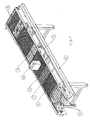
- Figure 1 is a perspective view of the overall tunnel oven according to the present invention;
- Figure 2 is a front view illustrating the tunnel oven shown in figure 1;
- Figure 3 illustrates a detail of the cleaning device for cleaning the chain conveying means of the tunnel oven shown in figure 1;
- Figure 4 is a schematic view illustrating the tunnel oven of figure 1, with the top covering removed therefrom, in order to show the hot air bottom flow outlets;
- Figure 5 is a broken away view of the tunnel oven of figure 1, specifically showing the deflection outlets or ports for deflecting the hot air top flows toward the oven fan;
- Figure 6 illustrates the arrangement of the hot air side outlets of the tunnel oven shown in figure 2;
- Figure 7 illustrates the conveying device for conveying the hot air flows to the top portion of the tunnel oven;
- Figure 8 illustrates the arrangement of the cooling fans of the chain conveying means at the front portion of the tunnel oven shown in figure 1;
- Figure 9 illustrates a modified embodiment of the tunnel oven shown in figure 8;
- Figure 10 illustrates a detail of a control device for controlling the bottom air flows of the oven tunnel shown in figure 4.
-
- The tunnel oven according to the present invention has been generally indicated in figure 1 by the reference number 1.
- Said tunnel oven comprises a
bottom supporting base 2, supporting a coveringelement 3 defining, with saidbase 4, thethermoshrinking chamber 4 of the tunnel oven. - Said
bottom base 2 comprises achain conveyor 5, provided for receiving a plurality ofarticles 6 to be packaged (in figure 1 said articles comprising bottles) which are preliminarily enveloped by a thermoshrinking material film 7. - Immediately under the
package 16 bearing surface, a plurality offans 8 are provided on the chain conveying means 5. - As is clearly shown in figure 4, the fans are arranged outside the covering
element 3 and are designed for cooling down thechain conveying means 5, thereby preventing the chain conveying means for achieving the thermoshrinking temperature of the film 7. - The control means for controlling the hot air flows exiting the bottom portion of the tunnel oven and directed to the packages are shown in figures 4, 8 and 10.
- More specifically, said hot air flow control means comprise a
plate 9, including a plurality of holes orslots 10, said plate extending through the overall length of the tunnel oven 1. - With said
plate 9 are associatedslider elements 11, preferably in a overlapping relationship with respect to said plate, said slider elements adjoining one another in a slidable manner and comprising a plurality ofholes 12 or perforations, registering with theholes 10 of saidplate 9. - The
slider elements 11 on theplate 9 are driven, in the direction of the arrows F of figure 8, by a driving mechanism including corresponding shafts 13 and levers 14, and in turn driven bycorresponding driving knobs 15. - Preferably, the
driving knobs 15 controlling the displacement of the slider elements ordrawers 11 are independently arranged on thebase 2, at both walls and on the two ends of the tunnel oven 1. - Thus, by operating the mentioned driving knobs, it is possible to achieve two different positions of the slider elements or
drawers 11 on theplate 9 and, more specifically: - 1. a full opening position in which the
holes 10 of theplate 9 are fully opened, and theholes 12 of theslider elements 11 are brought into registration with saidholes 10, and - 2. a fully closing position, in which the
holes 10 of theplate 9, with theslider elements 11 are arranged so that theholes 12 thereof are fully offset with respect to the holes ofsaid plate 9. -
- In this connection it should be apparent that it would be possible to achieve intermediate adjustments, providing a partial closure of the
holes 10 of theplate 9. - The
bottom base 2 of the tunnel 1 comprises acovering element 3 on which are mounted hotair circulating fans 17. - As is clearly shown in figure 2, the
fans 17 cause air to be directed inside thegap 18 of the coveringelement 3, in which are arrangedresistances 19 for heating said air. - The thus heated air flow is oriented toward the
base 2 and is upward directed, starting from thebottom 20 of thethermoshrinking chamber 4, by passing through the holes of theplate 9 and of theslider elements 11. - The air flow provided by
said fans 17 is also oriented in the direction of theperforated top plate 21 and perforatedtop slider element 22 assembly, having a construction and an arrangement analogous to those of thebottom plate 9 andbottom slider elements 11, as thereinabove disclosed. - In particular, the top slider elements or
drawers 22 comprises, at a respective end portion thereof,knobs 23 for driving said slider elements in the direction of the arrows F of figure 5, thereby closing, in a partial manner, the holes of theplate 21 for allowing air to enter thethermoshrinking chamber 4. - In order to provide the air flow exiting from the
bottom base 2 with a profile like that of thepackage 16, thetop slider elements 22 are so driven as to close the side surfaces of theplate 21, while leaving open the central portion of said plate, corresponding to the position of thepackage 16. - In this connection it should be apparent that the number of slider elements or drawers which are left open will depend on the size of the packages or number of the simultaneously processed packages.
- For some applications, in which the top region of the
packages 16 must not be affected by an excessive heat, the holes of thetop plate 21 are fully closed by theslider elements 22, and the air upward flowing from thebottom base 2 will be discharged through theopenings 25 formed through the top portion of theside walls 24 of thecovering element 3. - In the modified embodiment shown in figure 6, the air flow provided by the
fans 17 is partially deflected by abaffle 26, driven by acorresponding knob 27, provided on theside walls 24 at the rear portion of the tunnel oven 1, or processed packages outlet portions. - As shown in figure 2, the
fans 17 draw air from the thermoshrinking chamber in the direction indicated by thearrows 29, at afurther fan 28. - Then, as is shown in figure 7, the drawn air flow is at the start conveyed into a
cyclone 30 and being then conveyed from the latter, by deflectingwalls 31, through the overall length of thegap 18 of the covering element 3 (see thearrows 32 of figure 2). - The
top plate 21 andtop slider element 22 system (see figure 5) can be arranged, at an adjustable height above thebottom base 2 supporting thechain conveying means 5, by supportingbrackets 33 which can slide inslots 34 formed on saidside walls 24. - The adjusted in height position of the
plate 21 and of theslider elements 22 is locked by locking screws (not shown), operating between thewalls 22 andbrackets 33. - This height is selected depending on the size of the
packages 16 to be processed in the tunnel oven. - The cleaning of the
chain conveying means 5 is performed by the cleaning device shown in figure 3. - This cleaning device comprises a
rotary brush 35 arranged at thepackage 16 inlet region. - For providing an efficient cleaning of the
chain conveying means 5, the cleaningbrush 35 is advantageously adapted to rotate in a direction opposite to the sliding direction of the conveying chain. - The driving of the cleaning
brush 35 is at a temporary driving and is controlled by apneumatic cylinder 36 driving abrush supporting lever 37. - The
lever 37 supports moreover agear wheel 38 coupled to thebrush 35 and engaging with acorresponding gear wheel 39 for driving the chain conveying means. - Thus, as the
lever 37 is driven, the twogear wheels brush 35 to be moved toward the conveyingchain 5, to contact the latter. - The driving of the
cylinder 36 is controlled by a preset controlling program. - Advantageously, on the
package 16 outlet section, are provided a plurality ofIR lamps 40, arranged on theside walls 24 of thecovering element 3, as shown in figure 9. - If a plurality of packages arranged on a plurality of rows are supplied, then the
lamps 40 will be also arranged between a row of packages and another row thereof. - The mentioned lamps operate to concentrate the heat on the side walls of the packages, requiring a great amount of heat as necessary for properly extend the film.
- The invention, as disclosed and shown in the figures of the accompanying drawings, is susceptible to several modifications and variations, without departing from the scope of the following claims.
- Thus, for example, the plurality of
bottom slider elements 11 andtop slider elements 22 can be replaced by a single bottom slider element and a single top slider element, even arranged under the related plate, respectively 9 and 21.
Claims (30)
- A thermoshrinking tunnel oven (1) for making packages (16) of thermoshrinking material film (7), said tunnel oven comprising control means for controlling a thermoshrinking temperature of said film of said packages (16) housed inside a thermoshrinking chamber (4) of said oven, characterized in that said control means comprise a bottom plate (9) arranged under said packages (16), said plate (9) including a plurality of holes (10) having variable cross-sectional area for directing hot air supplied by hot air supplying fans (17) towards said packages (16).
- An oven according to Claim 1, characterized in that said oven comprises at least a bottom slider element (11) associated with said bottom plate (9) and including a plurality of perforations (12) which can be displaced between a position coinciding with said variable cross-section holes (10), thereby leaving said holes (10) fully open, and a position inward or outward offset of said holes, thereby fully closing said holes (10).
- An oven according to Claim 2, characterized in that said at least a bottom slider element (11) comprises a shaft (13) and lever (14) driving device, controlled by a corresponding knob (15), and designed to slidably drive said slider element (11) with respect to said plate (9).
- An oven according to Claim 2, characterized in that said oven comprises a plurality of mutually adjoining said bottom slider elements (11) thereby covering all said bottom plate (9).
- An oven according to Claim 1, characterized in that said thermoshrinking chamber (4) comprises a covering element (3) and a bottom supporting base (2), said covering element having walls defining a thermoshrinking air passage gap (18), for conveying thermoshrinking air under said bottom plate (9).
- An oven according to Claim 5, characterized in that in said gap (18) a plurality of heating resistances (19) for heating air supplied by said fans (17) are provided.
- An oven according to Claim 1, characterized in that said oven comprises moreover a perforated top plate (21) associated with at least a top slider element (22), also perforated, which is slidably mounted with respect to said perforated top plate (21) thereby opening and closing holes (10) of said perforated plate (9).
- An oven according to Claim 7, characterized in that said oven comprises a plurality of said top independently driven slider elements (22), covering all said perforated top plate (9).
- An oven according to Claim 5, characterized in that the side walls (24) of said covering elements (3) have side surfaces comprising a plurality of openings for discharging thermoshrinking air therefrom.
- An oven according to Claim 5, characterized in that said oven comprises moreover a baffle (26) arranged on said walls (24) of said covering elements.
- An oven according to Claim 5, characterized in that said fans comprises a cyclone (30) and deflecting walls (31) for conveying air through said gap (18).
- An oven according to Claim 7, characterized in that said oven comprises moreover adjustable height supporting means having a height which can be adjusted with respect to said top plate (21) and said at least a top slider element (22).
- An oven according to Claim 12, characterized in that said supporting means comprise supporting brackets (33) for supporting the plate and slider element assembly, said supporting brackets (33) being slidably mounted in corresponding slots (34) formed through said side walls (24) of said covering element (3).
- An oven according to Claim 1, characterized in that said oven comprises at least a chain conveyor means (5) for conveying said packages (16) in said thermoshrinking chamber (4), cooling fans for cooling said chain means being arranged under said conveying chain means (5), outside of said thermoshrinking chamber (4).
- An oven according to Claim 14, characterized in that said oven comprises moreover cleaning means (35) for cleaning said chain means (5) as said packages (16) are conveyed and thermoshrunk.
- An oven according to Claim 15, characterized in that said cleaning means (35) comprise a rotary brush (35) arranged at a package inlet region of said tunnel oven (1) and adapted to clean said chain means (5) as said chain conveys said packages (16).
- An oven according to Claim 16, characterized in that said cleaning brush (35) is swingably mounted to swing respectively between a position interfering against said chain means (5) for cleaning said chain means (5), and a rest position, in which said cleaning brush (35) is removed from said chain means (5).
- An oven according to Claim 17, characterized in that said oven comprises moreover a supporting lever (37) for supporting said cleaning brush (35) and a gear wheel (38) driving said cleaning brush (35) and supported by said lever (37), said gear wheel (38) being adapted to engage with a further gear wheel (39) for driving said chain means (5).
- An oven according to Claim 18, characterized in that said oven comprises moreover a driving cylinder (36) for driving said lever (37) from a disengagement position of said gear wheels (38, 39) to an engagement position of said gear wheels, in which said cleaning brush (35) is rotatively contacted with said chain means (5).
- An oven according to Claim 1, characterized in that said oven comprises moreover a plurality of IR lamps (40) arranged at a package outlet region, at a wall (24) of said covering element (3).
- An oven according to Claim 20, characterized in that said lamps (40) are arranged between rows of said packages (16) hereby irradiating the side walls of said packages (16).
- A method for packaging articles, in particular bottles, in a thermoshrinking film in an oven according to claims 1 to 21, comprising the steps of (a) controlling hot air flows thermoshrinking said film, and (b) controlling the flow rate and direction of said hot air flows, characterized in that said step (b) is performed by a further step (c) of adjusting the cross-section of the variable cross-section holes (10) of the bottom and top perforated plates (9,21) supplying hot air to a thermoshrinking chamber of said oven.
- A method according to Claim 22, characterized in that said step (c) is performed by causing said perforated slider elements (11,22) to slide on said perforated plates (9,12).
- A method according to Claim 22, characterized in that said step (b) is performed by independently driving the top slider elements (22) on their corresponding perforate plates (21).
- A method according to Claims 22 to 24, characterized in that the hot air flow has a profile corresponding to each said package, the top slider elements (22) being so arranged as to close the side surfaces of the corresponding plate, while leaving open a central portion of said plate, said central portion corresponding to the positions of said packages.
- A method according to Claims 22 to 25, characterized in that said method comprises the further step (d) of designing the size of said tunnel oven depending on the size of the packages to be processed, said step (d) being performed by raising or lowering said top plate (21) and top slider elements (22) system with respect to the package supporting bottom plate.
- A method according to Claims 22 to 26, characterized in that said method comprises moreover the step (e) of controlling the temperature of said chain means (5) conveying said packages.
- A method according to Claim 27, characterized in that said step (e) is performed by impinging air jets in the direction of said chain means (5), by fans (8) arranged outside of said thermoshrinking chamber.
- A method according to Claims 22 to 28, characterized in that said method comprises moreover the step (f) of cleaning said chain means (5) as said packages are conveyed thereby.
- A method according to Claim 29, characterized in that said cleaning step (f) is performed by temporaneuosly causing said brush (35) to contact said chain means (5) said brush being rotatively driven in a direction opposite to the chain means sliding direction.
Applications Claiming Priority (2)
| Application Number | Priority Date | Filing Date | Title |
|---|---|---|---|
| IT2001MI001825A ITMI20011825A1 (en) | 2001-08-29 | 2001-08-29 | THERMORETRATION TUNNEL OVEN FOR THE PRODUCTION OF FILM PACKAGING OF HEAT SHRINKABLE MATERIAL AND RE PACKAGING PROCEDURE |
| ITMI20011825 | 2001-08-29 |
Publications (4)
| Publication Number | Publication Date |
|---|---|
| EP1288129A2 EP1288129A2 (en) | 2003-03-05 |
| EP1288129A3 EP1288129A3 (en) | 2003-04-09 |
| EP1288129B1 true EP1288129B1 (en) | 2004-09-29 |
| EP1288129B2 EP1288129B2 (en) | 2007-12-05 |
Family
ID=11448308
Family Applications (1)
| Application Number | Title | Priority Date | Filing Date |
|---|---|---|---|
| EP02015841A Expired - Lifetime EP1288129B2 (en) | 2001-08-29 | 2002-07-16 | Thermoshrinking tunnel oven for making thermoshrinking plastic material film packages and the packaging method performed thereby |
Country Status (7)
| Country | Link |
|---|---|
| US (1) | US6648634B2 (en) |
| EP (1) | EP1288129B2 (en) |
| AT (1) | ATE277816T1 (en) |
| CA (1) | CA2397470C (en) |
| DE (1) | DE60201393T3 (en) |
| ES (1) | ES2230427T5 (en) |
| IT (1) | ITMI20011825A1 (en) |
Cited By (2)
| Publication number | Priority date | Publication date | Assignee | Title |
|---|---|---|---|---|
| DE102006058025A1 (en) * | 2006-12-07 | 2008-06-19 | Krones Ag | Device for generating process heat for a packaging device |
| DE102006060109A1 (en) * | 2006-12-20 | 2008-06-26 | Krones Ag | Machine for shrinking shrink film onto packaged goods and shrink-wrapping process |
Families Citing this family (50)
| Publication number | Priority date | Publication date | Assignee | Title |
|---|---|---|---|---|
| USD481049S1 (en) * | 2002-09-12 | 2003-10-21 | Lantech Management Corp. And Lantech Holding Corp. | Shrink wrap tunnel |
| WO2004094790A2 (en) * | 2003-04-17 | 2004-11-04 | Tower Solutions, Llc | Extendable/retractable support column |
| US20040231481A1 (en) | 2003-05-23 | 2004-11-25 | Floding Daniel Leonard | Apparatus for perforating or slitting heat shrink film |
| US7155876B2 (en) * | 2003-05-23 | 2007-01-02 | Douglas Machine, Inc. | Heat tunnel for film shrinking |
| USD517578S1 (en) * | 2003-10-07 | 2006-03-21 | Douglas Machine, Inc. | Shroud for a heat tunnel or the like |
| US7823366B2 (en) * | 2003-10-07 | 2010-11-02 | Douglas Machine, Inc. | Apparatus and method for selective processing of materials with radiant energy |
| ES2258369B1 (en) * | 2003-10-27 | 2007-11-16 | Ulma C Y E, S.Coop. | APPARATUS FOR SELECTIVELY AGAINST A FILM WRAPPING A PRODUCT. |
| US20050252174A1 (en) * | 2004-05-12 | 2005-11-17 | Tamko Roofing Products, Inc. | System for sealing a packaging wrapper |
| JP5064410B2 (en) * | 2005-12-09 | 2012-10-31 | ケー エッチ エス ゲーエムベーハー | Shrink process for manufacturing a stable container that can be conveyed and printed, and apparatus for performing the shrink process |
| DE102006036590A1 (en) * | 2006-08-04 | 2008-02-07 | Khs Ag | Method for shrinking a shrink wrap on packaging and apparatus for carrying out the method |
| JP5087268B2 (en) * | 2006-12-15 | 2012-12-05 | 株式会社フジシールインターナショナル | Shrink film heat shrink device |
| DE102007015753B4 (en) * | 2007-03-30 | 2018-08-09 | Khs Gmbh | Shrink tunnels, shrink gas heaters and shrink-wrap shrink wrap on packages or packages |
| US7811084B2 (en) * | 2008-01-25 | 2010-10-12 | Fu-Chuan Huang | Steam shrink oven |
| DE102010031800A1 (en) * | 2010-07-20 | 2012-01-26 | Krones Aktiengesellschaft | Arrangement and method for coupling a plurality of machine assemblies of a container treatment machine |
| WO2012058403A1 (en) | 2010-10-29 | 2012-05-03 | Tower Solutions, Llc | Extendable/retractable support column |
| NL2006753C2 (en) * | 2011-05-10 | 2012-11-13 | Fuji Seal Europe Bv | Apparatus for heat shrinking a film wrapping an object and method for operating the apparatus. |
| NL2006752C2 (en) * | 2011-05-10 | 2012-11-13 | Fuji Seal Europe Bv | Apparatus and method for heat shrinking a film wrapping an object. |
| RU2491214C1 (en) * | 2011-12-19 | 2013-08-27 | Общество с ограниченной ответственностью "Торговый дом "Пакверк" | Heat tunnel for packaging products in heat-shrink film and method of packaging products |
| RU2523491C2 (en) * | 2011-12-19 | 2014-07-20 | Общество с ограниченной ответственностью "Торговый дом "Пакверк" | Blower for heat tunnel of packing line and blower impeller |
| DE102012106600A1 (en) * | 2012-07-20 | 2014-06-12 | Krones Ag | Shrinking device with optimized energy management |
| US20140020344A1 (en) * | 2012-07-20 | 2014-01-23 | Tzu-Chin Hung | Shrink film heating device |
| US9162787B2 (en) * | 2012-12-05 | 2015-10-20 | Tzu-Chin Hung | Tangential airstream heat shrinking device of plastic film |
| EP2740673B1 (en) * | 2012-12-06 | 2015-07-08 | MSK - Verpackungs-Systeme GmbH | Method and device for applying a film to a stack of goods |
| CA2897201C (en) * | 2013-01-24 | 2020-07-14 | Ossid Llc | Method and apparatus for shrinking end seams around a product |
| DE102013101782A1 (en) * | 2013-02-22 | 2014-08-28 | Khs Gmbh | Shrink tunnel plant and an associated method for shrinking a shrink film on packing formations |
| DE102013103863A1 (en) * | 2013-04-17 | 2014-10-23 | Krones Aktiengesellschaft | Shrinking device and method for adjusting a shrinking device |
| DE102014104646B4 (en) * | 2014-04-02 | 2018-10-31 | Krones Aktiengesellschaft | Device for shrinking film onto articles |
| CN104044770B (en) * | 2014-06-16 | 2017-02-01 | 宋锡峰 | Floor shrink packaging machine and high-temperature hot air device |
| US10730652B2 (en) * | 2014-10-28 | 2020-08-04 | Heat Seal Llc | Packaging machine and method for fabricating sheet metal housing components |
| US11084616B2 (en) * | 2014-10-31 | 2021-08-10 | Arpac, Llc | Shrink wrap tunnel |
| DE102015111563A1 (en) * | 2015-07-16 | 2017-01-19 | Krones Aktiengesellschaft | shrinker |
| DE102016211632A1 (en) | 2016-06-28 | 2017-12-28 | Krones Aktiengesellschaft | Shrink tunnel and method for cleaning a transport device of a shrink tunnel |
| RU172041U1 (en) * | 2016-07-14 | 2017-06-27 | Общество с ограниченной ответственностью "РиаПласт" | INSTALLATION FOR OPENING OF PROCESSING CONTAINERS FROM POLYPROPYLENE FABRIC |
| IT201600115684A1 (en) * | 2016-11-16 | 2018-05-16 | Massimo Boldrini | Sterilization and depyrogenation machine for chemical-pharmaceutical containers, particularly of the energy-saving type. |
| US11549753B2 (en) * | 2017-01-24 | 2023-01-10 | Illinois Tool Works Inc. | Laminar flow shrink oven |
| CN107356112B (en) * | 2017-08-22 | 2024-03-08 | 盐城市凌源电热设备有限公司 | Tunnel type heat shrinkage furnace with LED lamp tube |
| DE102017119145A1 (en) * | 2017-08-22 | 2019-02-28 | Krones Aktiengesellschaft | Shrinking device and method for sucking air from an interior of a shrinking device |
| IT201700100979A1 (en) * | 2017-09-08 | 2019-03-08 | Ocme Srl | THERMORETRATION OVEN, PARTICULARLY FOR THE FORMATION OF BULBS OF PRODUCTS WRAPPED BY A THERMORETRABLE FILM. |
| US10920444B2 (en) | 2018-03-22 | 2021-02-16 | Tower Solutions, Llc | Mobile tower for transportation and remote deployment |
| CN109436468A (en) * | 2018-12-25 | 2019-03-08 | 重庆具码科技有限公司 | A kind of pre-packaged device for packing engine |
| FR3094779B1 (en) | 2019-04-02 | 2021-05-14 | C E R M E X Constructions Etudes Et Rech De Materiels Pour Lemballage Dexpedition | Device for heating batches of coated products and packaging installation by bundling batches of products |
| FR3095689B1 (en) * | 2019-04-30 | 2024-01-12 | C E R M E X Constructions Etudes Et Rech De Materiels Pour Lemballage Dexpedition | Heating device, packaging installation by bundling with such a device and method of circulating heated air flow in this device. |
| CN113022990B (en) * | 2021-03-08 | 2022-11-18 | 四川达优机械有限公司 | Thermal shrinkage packaging machine |
| US11970303B2 (en) | 2022-01-26 | 2024-04-30 | The Procter & Gamble Company | Infrared-assisted shrink wrap product bundling |
| KR102457187B1 (en) * | 2022-08-09 | 2022-10-20 | 서명수 | Forced convection type tunnel dryer |
| DE102022131134A1 (en) * | 2022-11-24 | 2024-05-29 | Krones Aktiengesellschaft | Shrinking device |
| CN116101576A (en) * | 2023-02-15 | 2023-05-12 | 广州达意隆包装机械股份有限公司 | The adjustment mechanism of the air box in the oven of the film wrapping machine |
| TWM646063U (en) * | 2023-05-04 | 2023-09-11 | 洪子欽 | Air hole adjustment device for packaging heat shrink furnace |
| DE102023134589A1 (en) * | 2023-12-11 | 2025-06-12 | Krones Aktiengesellschaft | Shrinking device and method for shrinking a shrink material onto articles at least partially wrapped with the shrink material |
| DE102024125550A1 (en) * | 2024-09-05 | 2026-03-05 | Krones Aktiengesellschaft | Device for shrinking a film onto an article |
Family Cites Families (20)
| Publication number | Priority date | Publication date | Assignee | Title |
|---|---|---|---|---|
| US3378989A (en) * | 1965-02-24 | 1968-04-23 | Doughboy Ind Inc | Packaging machinery |
| AU1413566A (en) * | 1966-11-18 | 1969-03-13 | W. R. Grace Australia | Packaging |
| CH468278A (en) * | 1967-07-21 | 1969-02-15 | Beck Hans | Hot air heated shrink tunnel |
| US3808767A (en) * | 1971-01-11 | 1974-05-07 | Master Packaging Equipment Inc | Methods of and apparatus for shrink packaging |
| US3818182A (en) * | 1971-02-08 | 1974-06-18 | Bonnierfoeretagen Ab | Device for shrinking a wrapper, consisting of a plastic sheeting shrinkable by heating, around a transport unit |
| US3760154A (en) * | 1972-02-29 | 1973-09-18 | Signode Corp | Apparatus for heat-shrinking a plastic film on a load |
| US3957155A (en) † | 1975-05-29 | 1976-05-18 | Enchelmaier Harvard W K | Conveyor cleaning device |
| DE2752965A1 (en) * | 1977-11-28 | 1979-05-31 | Fischer & Co Kg H | Heating tunnel for shrink foil wrapping - includes blower nozzle to produce air circulation |
| ZA80193B (en) † | 1980-01-14 | 1981-08-26 | Merwe D V D | Method of and apparatus for cleaning a conveyor belt |
| IT1169175B (en) * | 1983-02-23 | 1987-05-27 | Gambetti Mario Baumer | MACHINE FOR PACKING CONTINUOUSLY MOVING ITEMS WITH A TAPE OF HEAT-SHRINKABLE MATERIAL |
| US4538363A (en) * | 1984-02-01 | 1985-09-03 | Zagoroff Dimiter S | Shrink oven |
| US4965435A (en) * | 1985-10-15 | 1990-10-23 | Donald P. Smith | Forced convection tunnel oven |
| US4597247A (en) * | 1985-10-15 | 1986-07-01 | The Mead Corporation | Method and apparatus for applying controlled heat to a group of articles disposed within a shrink film wrapper |
| JPH01252886A (en) * | 1988-03-31 | 1989-10-09 | Central Glass Co Ltd | Heat working furnace and heat treatment effected thereby |
| DE8912256U1 (en) * | 1989-10-14 | 1990-02-08 | Heinz Wulfert Maschinenbau GmbH & Co KG, 5620 Velbert | Shrink film packaging machine |
| FR2680154B1 (en) * | 1991-08-07 | 1993-11-19 | Probag | METHOD AND MACHINE FOR OVERPACKING LUGGAGE OF USERS OF VARIOUS MEANS OF TRANSPORT. |
| US5390477A (en) * | 1991-11-19 | 1995-02-21 | Mcneilab, Inc. | System for applying a heat shrinkable sleeve to a container |
| EP0731769B1 (en) † | 1993-12-22 | 1998-08-26 | HARPER, Christopher Roger | Cleaning device for endless conveyor |
| FR2719556B1 (en) * | 1994-05-09 | 1996-07-19 | Probag Sa | Baggage overwrapping machine. |
| WO1996002442A1 (en) † | 1994-07-18 | 1996-02-01 | Brian Tucker | Conveyor belt cleaning |
-
2001
- 2001-08-29 IT IT2001MI001825A patent/ITMI20011825A1/en unknown
-
2002
- 2002-07-16 ES ES02015841T patent/ES2230427T5/en not_active Expired - Lifetime
- 2002-07-16 EP EP02015841A patent/EP1288129B2/en not_active Expired - Lifetime
- 2002-07-16 AT AT02015841T patent/ATE277816T1/en active
- 2002-07-16 DE DE60201393T patent/DE60201393T3/en not_active Expired - Lifetime
- 2002-07-19 US US10/199,534 patent/US6648634B2/en not_active Expired - Fee Related
- 2002-08-08 CA CA002397470A patent/CA2397470C/en not_active Expired - Fee Related
Cited By (2)
| Publication number | Priority date | Publication date | Assignee | Title |
|---|---|---|---|---|
| DE102006058025A1 (en) * | 2006-12-07 | 2008-06-19 | Krones Ag | Device for generating process heat for a packaging device |
| DE102006060109A1 (en) * | 2006-12-20 | 2008-06-26 | Krones Ag | Machine for shrinking shrink film onto packaged goods and shrink-wrapping process |
Also Published As
| Publication number | Publication date |
|---|---|
| CA2397470A1 (en) | 2003-02-28 |
| DE60201393T3 (en) | 2008-06-26 |
| DE60201393D1 (en) | 2004-11-04 |
| EP1288129A3 (en) | 2003-04-09 |
| EP1288129A2 (en) | 2003-03-05 |
| EP1288129B2 (en) | 2007-12-05 |
| ES2230427T3 (en) | 2005-05-01 |
| US20030044744A1 (en) | 2003-03-06 |
| ES2230427T5 (en) | 2008-05-01 |
| CA2397470C (en) | 2009-07-28 |
| DE60201393T2 (en) | 2005-09-22 |
| ITMI20011825A1 (en) | 2003-03-01 |
| US6648634B2 (en) | 2003-11-18 |
| ITMI20011825A0 (en) | 2001-08-29 |
| ATE277816T1 (en) | 2004-10-15 |
Similar Documents
| Publication | Publication Date | Title |
|---|---|---|
| EP1288129B2 (en) | Thermoshrinking tunnel oven for making thermoshrinking plastic material film packages and the packaging method performed thereby | |
| US4834063A (en) | Food cooking oven with duct fingers and method | |
| CA2988729C (en) | Convection oven having removable air plenums | |
| US7886658B2 (en) | Speed cooking oven with improved radiant mode | |
| US6539934B2 (en) | Multiconveyor convection oven | |
| EP2707293B1 (en) | Apparatus for heat shrinking a film wrapping an object and method for operating the apparatus | |
| US20100058936A1 (en) | Recirculating end cover plates for a conveyor oven | |
| US20080105249A1 (en) | Speed cooking oven with radiant mode | |
| JPH10169990A (en) | Cooking oven for cooking food and cooking method | |
| EP1566594A1 (en) | Process and device for aerating and/or venting a cooking oven | |
| US8056470B2 (en) | Tempering channel for confectioneries | |
| US3430358A (en) | Shrink tunnel with conveyer and air directing means | |
| US6517882B2 (en) | Food oven with even heat distribution | |
| US7296995B2 (en) | Circulating air oven | |
| US5285582A (en) | Oven for a transverse stretching apparatus | |
| EP4037531B1 (en) | Multi-cavity oven with removable shelf comprising a removable baffle plate | |
| JPH0144290B2 (en) | ||
| US20050284466A1 (en) | Baking oven | |
| EP0928137B1 (en) | Device for the treatment of food products | |
| US20090120304A1 (en) | Apparatus for Cooking Food | |
| JP7788311B2 (en) | heating device | |
| KR20010007699A (en) | apparatus for heating a wafer | |
| WO2018090101A1 (en) | Apparatus and method for reducing cooking time | |
| HK1023905B (en) | Process and apparatus for the treatment of flat-form material, especially of printed circuit boards |
Legal Events
| Date | Code | Title | Description |
|---|---|---|---|
| PUAI | Public reference made under article 153(3) epc to a published international application that has entered the european phase |
Free format text: ORIGINAL CODE: 0009012 |
|
| PUAL | Search report despatched |
Free format text: ORIGINAL CODE: 0009013 |
|
| AK | Designated contracting states |
Kind code of ref document: A2 Designated state(s): AT BE BG CH CY CZ DE DK EE ES FI FR GB GR IE IT LI LU MC NL PT SE SK TR |
|
| AX | Request for extension of the european patent |
Extension state: AL LT LV MK RO SI |
|
| AK | Designated contracting states |
Kind code of ref document: A3 Designated state(s): AT BE BG CH CY CZ DE DK EE ES FI FR GB GR IE IT LI LU MC NL PT SE SK TR |
|
| AX | Request for extension of the european patent |
Extension state: AL LT LV MK RO SI |
|
| 17P | Request for examination filed |
Effective date: 20030610 |
|
| 17Q | First examination report despatched |
Effective date: 20030917 |
|
| AKX | Designation fees paid |
Designated state(s): AT BE BG CH CY CZ DE DK EE ES FI FR GB GR IE IT LI LU MC NL PT SE SK TR |
|
| GRAP | Despatch of communication of intention to grant a patent |
Free format text: ORIGINAL CODE: EPIDOSNIGR1 |
|
| GRAS | Grant fee paid |
Free format text: ORIGINAL CODE: EPIDOSNIGR3 |
|
| GRAA | (expected) grant |
Free format text: ORIGINAL CODE: 0009210 |
|
| AK | Designated contracting states |
Kind code of ref document: B1 Designated state(s): AT BE BG CH CY CZ DE DK EE ES FI FR GB GR IE IT LI LU MC NL PT SE SK TR |
|
| PG25 | Lapsed in a contracting state [announced via postgrant information from national office to epo] |
Ref country code: EE Free format text: LAPSE BECAUSE OF FAILURE TO SUBMIT A TRANSLATION OF THE DESCRIPTION OR TO PAY THE FEE WITHIN THE PRESCRIBED TIME-LIMIT Effective date: 20040929 Ref country code: CH Free format text: LAPSE BECAUSE OF FAILURE TO SUBMIT A TRANSLATION OF THE DESCRIPTION OR TO PAY THE FEE WITHIN THE PRESCRIBED TIME-LIMIT Effective date: 20040929 Ref country code: NL Free format text: LAPSE BECAUSE OF FAILURE TO SUBMIT A TRANSLATION OF THE DESCRIPTION OR TO PAY THE FEE WITHIN THE PRESCRIBED TIME-LIMIT Effective date: 20040929 Ref country code: LI Free format text: LAPSE BECAUSE OF FAILURE TO SUBMIT A TRANSLATION OF THE DESCRIPTION OR TO PAY THE FEE WITHIN THE PRESCRIBED TIME-LIMIT Effective date: 20040929 Ref country code: BG Free format text: LAPSE BECAUSE OF FAILURE TO SUBMIT A TRANSLATION OF THE DESCRIPTION OR TO PAY THE FEE WITHIN THE PRESCRIBED TIME-LIMIT Effective date: 20040929 Ref country code: FI Free format text: LAPSE BECAUSE OF FAILURE TO SUBMIT A TRANSLATION OF THE DESCRIPTION OR TO PAY THE FEE WITHIN THE PRESCRIBED TIME-LIMIT Effective date: 20040929 Ref country code: BE Free format text: LAPSE BECAUSE OF FAILURE TO SUBMIT A TRANSLATION OF THE DESCRIPTION OR TO PAY THE FEE WITHIN THE PRESCRIBED TIME-LIMIT Effective date: 20040929 Ref country code: SK Free format text: LAPSE BECAUSE OF FAILURE TO SUBMIT A TRANSLATION OF THE DESCRIPTION OR TO PAY THE FEE WITHIN THE PRESCRIBED TIME-LIMIT Effective date: 20040929 Ref country code: CZ Free format text: LAPSE BECAUSE OF FAILURE TO SUBMIT A TRANSLATION OF THE DESCRIPTION OR TO PAY THE FEE WITHIN THE PRESCRIBED TIME-LIMIT Effective date: 20040929 |
|
| REG | Reference to a national code |
Ref country code: GB Ref legal event code: FG4D |
|
| REG | Reference to a national code |
Ref country code: CH Ref legal event code: EP |
|
| REG | Reference to a national code |
Ref country code: IE Ref legal event code: FG4D |
|
| REF | Corresponds to: |
Ref document number: 60201393 Country of ref document: DE Date of ref document: 20041104 Kind code of ref document: P |
|
| PG25 | Lapsed in a contracting state [announced via postgrant information from national office to epo] |
Ref country code: GR Free format text: LAPSE BECAUSE OF FAILURE TO SUBMIT A TRANSLATION OF THE DESCRIPTION OR TO PAY THE FEE WITHIN THE PRESCRIBED TIME-LIMIT Effective date: 20041229 Ref country code: DK Free format text: LAPSE BECAUSE OF FAILURE TO SUBMIT A TRANSLATION OF THE DESCRIPTION OR TO PAY THE FEE WITHIN THE PRESCRIBED TIME-LIMIT Effective date: 20041229 Ref country code: SE Free format text: LAPSE BECAUSE OF FAILURE TO SUBMIT A TRANSLATION OF THE DESCRIPTION OR TO PAY THE FEE WITHIN THE PRESCRIBED TIME-LIMIT Effective date: 20041229 |
|
| NLV1 | Nl: lapsed or annulled due to failure to fulfill the requirements of art. 29p and 29m of the patents act | ||
| REG | Reference to a national code |
Ref country code: CH Ref legal event code: PL |
|
| REG | Reference to a national code |
Ref country code: ES Ref legal event code: FG2A Ref document number: 2230427 Country of ref document: ES Kind code of ref document: T3 |
|
| PG25 | Lapsed in a contracting state [announced via postgrant information from national office to epo] |
Ref country code: CY Free format text: LAPSE BECAUSE OF FAILURE TO SUBMIT A TRANSLATION OF THE DESCRIPTION OR TO PAY THE FEE WITHIN THE PRESCRIBED TIME-LIMIT Effective date: 20050716 Ref country code: LU Free format text: LAPSE BECAUSE OF NON-PAYMENT OF DUE FEES Effective date: 20050716 |
|
| PG25 | Lapsed in a contracting state [announced via postgrant information from national office to epo] |
Ref country code: IE Free format text: LAPSE BECAUSE OF NON-PAYMENT OF DUE FEES Effective date: 20050718 |
|
| PLBI | Opposition filed |
Free format text: ORIGINAL CODE: 0009260 |
|
| PG25 | Lapsed in a contracting state [announced via postgrant information from national office to epo] |
Ref country code: MC Free format text: LAPSE BECAUSE OF NON-PAYMENT OF DUE FEES Effective date: 20050731 |
|
| PLAX | Notice of opposition and request to file observation + time limit sent |
Free format text: ORIGINAL CODE: EPIDOSNOBS2 |
|
| 26 | Opposition filed |
Opponent name: KRONES AG Effective date: 20050629 |
|
| ET | Fr: translation filed | ||
| PLAF | Information modified related to communication of a notice of opposition and request to file observations + time limit |
Free format text: ORIGINAL CODE: EPIDOSCOBS2 |
|
| PLBB | Reply of patent proprietor to notice(s) of opposition received |
Free format text: ORIGINAL CODE: EPIDOSNOBS3 |
|
| REG | Reference to a national code |
Ref country code: IE Ref legal event code: MM4A |
|
| PLAY | Examination report in opposition despatched + time limit |
Free format text: ORIGINAL CODE: EPIDOSNORE2 |
|
| PLAH | Information related to despatch of examination report in opposition + time limit modified |
Free format text: ORIGINAL CODE: EPIDOSCORE2 |
|
| PLBC | Reply to examination report in opposition received |
Free format text: ORIGINAL CODE: EPIDOSNORE3 |
|
| PLAY | Examination report in opposition despatched + time limit |
Free format text: ORIGINAL CODE: EPIDOSNORE2 |
|
| PLBC | Reply to examination report in opposition received |
Free format text: ORIGINAL CODE: EPIDOSNORE3 |
|
| PUAH | Patent maintained in amended form |
Free format text: ORIGINAL CODE: 0009272 |
|
| STAA | Information on the status of an ep patent application or granted ep patent |
Free format text: STATUS: PATENT MAINTAINED AS AMENDED |
|
| 27A | Patent maintained in amended form |
Effective date: 20071205 |
|
| AK | Designated contracting states |
Kind code of ref document: B2 Designated state(s): AT BE BG CH CY CZ DE DK EE ES FI FR GB GR IE IT LI LU MC NL PT SE SK TR |
|
| PG25 | Lapsed in a contracting state [announced via postgrant information from national office to epo] |
Ref country code: PT Free format text: LAPSE BECAUSE OF NON-PAYMENT OF DUE FEES Effective date: 20050228 |
|
| REG | Reference to a national code |
Ref country code: ES Ref legal event code: DC2A Date of ref document: 20080220 Kind code of ref document: T5 |
|
| ET3 | Fr: translation filed ** decision concerning opposition | ||
| PGFP | Annual fee paid to national office [announced via postgrant information from national office to epo] |
Ref country code: FR Payment date: 20110801 Year of fee payment: 10 |
|
| PGFP | Annual fee paid to national office [announced via postgrant information from national office to epo] |
Ref country code: GB Payment date: 20110708 Year of fee payment: 10 Ref country code: DE Payment date: 20110728 Year of fee payment: 10 Ref country code: TR Payment date: 20110708 Year of fee payment: 10 Ref country code: AT Payment date: 20110712 Year of fee payment: 10 Ref country code: ES Payment date: 20110712 Year of fee payment: 10 |
|
| PGFP | Annual fee paid to national office [announced via postgrant information from national office to epo] |
Ref country code: IT Payment date: 20110721 Year of fee payment: 10 |
|
| REG | Reference to a national code |
Ref country code: AT Ref legal event code: MM01 Ref document number: 277816 Country of ref document: AT Kind code of ref document: T Effective date: 20120716 |
|
| GBPC | Gb: european patent ceased through non-payment of renewal fee |
Effective date: 20120716 |
|
| REG | Reference to a national code |
Ref country code: FR Ref legal event code: ST Effective date: 20130329 |
|
| PG25 | Lapsed in a contracting state [announced via postgrant information from national office to epo] |
Ref country code: DE Free format text: LAPSE BECAUSE OF NON-PAYMENT OF DUE FEES Effective date: 20130201 Ref country code: FR Free format text: LAPSE BECAUSE OF NON-PAYMENT OF DUE FEES Effective date: 20120731 Ref country code: GB Free format text: LAPSE BECAUSE OF NON-PAYMENT OF DUE FEES Effective date: 20120716 |
|
| REG | Reference to a national code |
Ref country code: DE Ref legal event code: R119 Ref document number: 60201393 Country of ref document: DE Effective date: 20130201 |
|
| PG25 | Lapsed in a contracting state [announced via postgrant information from national office to epo] |
Ref country code: IT Free format text: LAPSE BECAUSE OF NON-PAYMENT OF DUE FEES Effective date: 20120716 |
|
| PG25 | Lapsed in a contracting state [announced via postgrant information from national office to epo] |
Ref country code: AT Free format text: LAPSE BECAUSE OF NON-PAYMENT OF DUE FEES Effective date: 20120716 |
|
| REG | Reference to a national code |
Ref country code: ES Ref legal event code: FD2A Effective date: 20131030 |
|
| PG25 | Lapsed in a contracting state [announced via postgrant information from national office to epo] |
Ref country code: ES Free format text: LAPSE BECAUSE OF NON-PAYMENT OF DUE FEES Effective date: 20120717 |
|
| PG25 | Lapsed in a contracting state [announced via postgrant information from national office to epo] |
Ref country code: TR Free format text: LAPSE BECAUSE OF NON-PAYMENT OF DUE FEES Effective date: 20120716 |