EP1288020A2 - Clip for fixing wheel covers - Google Patents
Clip for fixing wheel covers Download PDFInfo
- Publication number
- EP1288020A2 EP1288020A2 EP02255928A EP02255928A EP1288020A2 EP 1288020 A2 EP1288020 A2 EP 1288020A2 EP 02255928 A EP02255928 A EP 02255928A EP 02255928 A EP02255928 A EP 02255928A EP 1288020 A2 EP1288020 A2 EP 1288020A2
- Authority
- EP
- European Patent Office
- Prior art keywords
- wheel
- wheel rim
- assembly
- clip
- base portion
- Prior art date
- Legal status (The legal status is an assumption and is not a legal conclusion. Google has not performed a legal analysis and makes no representation as to the accuracy of the status listed.)
- Withdrawn
Links
- 239000000853 adhesive Substances 0.000 claims description 10
- 230000001070 adhesive effect Effects 0.000 claims description 10
- 239000000463 material Substances 0.000 claims description 9
- 229910001220 stainless steel Inorganic materials 0.000 claims description 3
- 239000010935 stainless steel Substances 0.000 claims description 3
- -1 for example Substances 0.000 description 3
- 239000002184 metal Substances 0.000 description 2
- 238000000034 method Methods 0.000 description 2
- 238000003466 welding Methods 0.000 description 2
- 239000003292 glue Substances 0.000 description 1
- 238000004519 manufacturing process Methods 0.000 description 1
- 238000007789 sealing Methods 0.000 description 1
- 239000000126 substance Substances 0.000 description 1
- 239000013589 supplement Substances 0.000 description 1
Images

Classifications
-
- B—PERFORMING OPERATIONS; TRANSPORTING
- B60—VEHICLES IN GENERAL
- B60B—VEHICLE WHEELS; CASTORS; AXLES FOR WHEELS OR CASTORS; INCREASING WHEEL ADHESION
- B60B7/00—Wheel cover discs, rings, or the like, for ornamenting, protecting, venting, or obscuring, wholly or in part, the wheel body, rim, hub, or tyre sidewall, e.g. wheel cover discs, wheel cover discs with cooling fins
- B60B7/06—Fastening arrangements therefor
- B60B7/10—Fastening arrangements therefor comprising a plurality of spaced spring clips individually mounted on the cover, e.g. riveted, welded or readily releasable
- B60B7/105—Fastening arrangements therefor comprising a plurality of spaced spring clips individually mounted on the cover, e.g. riveted, welded or readily releasable the spring clip mounted on the rim
Definitions
- the present invention relates to wheel rim arrangements. More specifically, the invention relates to a wheel clip that secures a wheel cover to a wheel rim.
- Wheel rim arrangements for vehicles may include a wheel cover. Therefore, there is a need in the art to attach a wheel cover to the wheel rim.
- a wheel rim assembly including a wheel rim and a wheel cover
- the wheel rim assembly comprises a clip assembly for attaching a wheel cover to a wheel rim.
- the clip assembly includes a bracket portion and a base portion.
- the bracket portion affixes to the wheel cover.
- the base portion is a planar strip that is curved to conform and affix to an inner periphery of the wheel rim.
- a second embodiment of the invention is a wheel rim assembly.
- the bracket portion comprises a first end and a second end.
- the second end comprises a spring clip and a Dzus fastener that allows attachment of the wheel clip assembly to the wheel cover.
- the spring clip is permanently affixed to the second end by protrusions that extend from the second end in opposing relationship about a passage that provides clearance for the Dzus fastener for engagement about the spring clip.
- the Dzus fastener is twisted and fastened about the spring clip in order to draw the wheel cover adjacent to the second end of the bracket portion.
- the base portion comprises an adhesive about an outer side for adhering the wheel clip assembly to the inner periphery of the wheel rim.
- the wheel rim assembly comprises means for affixing a wheel cover to a wheel rim, means for affixing to a wheel cover, and means for affixing to a wheel rim.
- Figures 1 is a perspective view of a wheel clip assembly
- Figure 2 is another perspective view of a wheel clip assembly affixed to an inner periphery of wheel rim
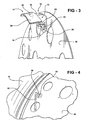
- Figure 3 is another perspective view of the wheel clip assembly fastened to the interior of a wheel cover
- Figure 4 is a perspective view of the exterior of a wheel cover and a fastener.
- a wheel clip assembly which is shown generally at 10 comprises means for affixing, such as a bracket portion 12, to a wheel cover 36 ( Figures 3-4), and means for affixing, such as base portion 14, to a wheel rim 30 ( Figure 2).
- the bracket portion 12 includes a first end 16 and a second end 18.
- the base portion 14 is defined to be a planar strip that is curved to conform to the inner periphery 28 of the wheel rim 30.
- the bracket portion 12 and base portion 14 may be manufactured with a single, rigid material, such as, for example, stainless steel or any suitable plastic or metal.
- the bracket portion 12 may be manufactured from a first rigid material, such as, for example, metal, and the base portion 14 may be manufactured from a second rigid material, such as, for example, plastic. If the bracket portion 12 and the base portion 14 are manufactured from two different matezials, the first end 16 of the bracket portion 12 is adjacently coupled to the base portion 14 by either a conventional adhesive, welding, bolting, or any other desirable fastening technique.
- the second end 18 of the bracket portion 12 provides fastening means, such as, for example, a spring clip 20 and a fastening stud 22 that allows attachment of the wheel clip assembly 10 to the wheel cover 36.
- the wheel cover 36 may be an aerodynamic wheel cover in the shape of a dome with a single passage defined by a narrow diameter about its apex.
- the aerodynamic wheel cover is described in non-provisional U.S. Patent Application Serial No. / filed on August , 2002 and provisional U.S. Patent Application Serial No. 60/315,205 filed on August 27,2001, which are incorporated herein by reference.
- the aerodynamic wheel cover is under assignment to inventor of the present patent application and is commercially available from the Aero-Chex Corporation of Nyack-on-the-Hudson, NY.
- the spring clip 20 may be permanently affixed to the second end 18 of the bracket portion 12.
- the fastening means may further comprise protrusions 24 that extend from second end 18 in opposing relationship about a passage 26 that provides clearance for the fastening stud 22 for engagement about the spring clip 20. As illustrated, the fastening stud 22 may be inserted through the passage 26, twisted about the passage 26, and locked about the spring clip 20.
- the fastening stud 22 may be any desirable fastener, such as, for example, a Dzus fastener.
- the Dzus fastener 22 may be twisted at a key portion 40 ( Figure 4) through the use of an Allen Wrench 42 ( Figure 4) so that it may be locked on the spring clip 20.
- the spring clip 20 draws the Dzus fastener 22 away from the second end 18 when the Allen Wrench 42 is turned and creates a sufficient pressure where the diameter of the key portion 40 meets the wheel cover 36.
- the wheel clip assembly 10 is first located at an inner periphery 28 of a wheel rim 30.
- This principle combination provides circumferential support of the wheel clip assembly 10 to the wheel rim 30.
- the base portion 14 is desirably positioned within the inner periphery 28 of the wheel rim 30 so that the second end 18 may be on the same plane of an outer circumference 32 of the wheel rim 30.
- the wheel clip assembly 10 adheres to the inner periphery 28 of the wheel rim 30 by use of the adhesive 34 about an outer side 36 of the base portion 14.
- the adhesive 34 may be a doubled-sided tape, glue, or any substance that may withstand the intense heat generated by a vehicle braking system and tire 11.
- the adhesive 34 may be preferably selected to have properties that will increases its adhesivness over time when intense heat is exhibited on the wheel rim 30. As the vehicle is moving, centrifugal forces acting on the wheel clip assembly 10 also increases the adhesivness of the adhesive 34 which supplements the integrity of the circumferential support ofthe wheel clip assembly 10 to the wheel rim 30.
- the use of adhesive 34 on the base portion 14 gives the flexibility of attaching the wheel clip assembly 10 to a variety of wheel rims having different diameters. Alternatively, wheel clip assembly 10 may adhere to the inner periphery 28 of the wheel rim 30 by directly welding, bolting, or with an other desirable manufacturing technique.
- the wheel clip assembly 10 when the wheel clip assembly 10 is adhered to the inner periphery 28 of the wheel rim 30, the wheel clip assembly 10 is then desirably fastened to the interior of a wheel cover 36.
- the second end 18 of the bracket portion 12 provides fastening means to the wheel cover 36 by extending the Dzus fastener 22 though an opening 38 ( Figure 4) in the wheel cover 36 and the passage 26 ( Figure 3) of the second end 18.
- the Dzus fastener has a key portion 40 with a larger diameter than the opening 38 so that proper attachment of the wheel cover 36 to the clip assembly 10 may be executed. Even further, if the aerodynamic wheel cover is used, the key portion 40 with the larger diameter provides sufficient sealing of the opening 38 such that a low pressure may by maintained in the wheel cover such that it may maintain a vacuum to expedite warm air from the wheel rim 30 at the single narrow passage about its apex.
- the Allen Wrench 42 is inserted into the key portion 40 of the Dzus fastener 22 and is twisted so that proper locking of the wheel cover 36 to the clip assembly 10 occurs. Sufficient pressure exerted by the Dzus fastener 22 draws the wheel cover 36 adjacent to second end 18 of the bracket portion 12.
- the wheel clip assembly 10 provides an intermediate, lateral attachment of the wheel cover 36 to the wheel rim 30.
- Examples of possible vehicle applications of the wheel clip assembly 10 may be Class 8 Tractors, Class 8 Trailers, Class 7/6 Tractors, Class 5/4/3 Trucks, Class 2C Trucks, School Buses, or even Greyhound-type Buses.
Landscapes
- Engineering & Computer Science (AREA)
- Mechanical Engineering (AREA)
- Connection Of Plates (AREA)
- Tires In General (AREA)
Abstract
Description
- This application claims priority to U.S. Provisional Application Number 60/315,190 filed August 27, 2001.
- The present invention relates to wheel rim arrangements. More specifically, the invention relates to a wheel clip that secures a wheel cover to a wheel rim.
- Wheel rim arrangements for vehicles may include a wheel cover. Therefore, there is a need in the art to attach a wheel cover to the wheel rim.
- In a first embodiment of the invention, a wheel rim assembly including a wheel rim and a wheel cover is described. The wheel rim assembly comprises a clip assembly for attaching a wheel cover to a wheel rim. The clip assembly includes a bracket portion and a base portion. The bracket portion affixes to the wheel cover. The base portion is a planar strip that is curved to conform and affix to an inner periphery of the wheel rim.
- A second embodiment of the invention is a wheel rim assembly. In this embodiment, the bracket portion comprises a first end and a second end. The second end comprises a spring clip and a Dzus fastener that allows attachment of the wheel clip assembly to the wheel cover. The spring clip is permanently affixed to the second end by protrusions that extend from the second end in opposing relationship about a passage that provides clearance for the Dzus fastener for engagement about the spring clip. The Dzus fastener is twisted and fastened about the spring clip in order to draw the wheel cover adjacent to the second end of the bracket portion. The base portion comprises an adhesive about an outer side for adhering the wheel clip assembly to the inner periphery of the wheel rim.
- Another embodiment of the invention is a wheel rim assembly. In this embodiment, the wheel rim assembly comprises means for affixing a wheel cover to a wheel rim, means for affixing to a wheel cover, and means for affixing to a wheel rim.
- Various additional aspects and advantages of this invention will become apparent to those skilled in the art from the following detailed description of the preferred embodiment, when read in light of the accompanying drawings.
- Figures 1 is a perspective view of a wheel clip assembly;
- Figure 2 is another perspective view of a wheel clip assembly affixed to an inner periphery of wheel rim;
- Figure 3 is another perspective view of the wheel clip assembly fastened to the interior of a wheel cover;
- Figure 4 is a perspective view of the exterior of a wheel cover and a fastener.
- As shown in Figure 1, a wheel clip assembly, which is shown generally at 10 comprises means for affixing, such as a
bracket portion 12, to a wheel cover 36 (Figures 3-4), and means for affixing, such asbase portion 14, to a wheel rim 30 (Figure 2). Thebracket portion 12 includes afirst end 16 and asecond end 18. Thebase portion 14 is defined to be a planar strip that is curved to conform to theinner periphery 28 of thewheel rim 30. - The
bracket portion 12 andbase portion 14 may be manufactured with a single, rigid material, such as, for example, stainless steel or any suitable plastic or metal. Alternatively, if desired, thebracket portion 12 may be manufactured from a first rigid material, such as, for example, metal, and thebase portion 14 may be manufactured from a second rigid material, such as, for example, plastic. If thebracket portion 12 and thebase portion 14 are manufactured from two different matezials, thefirst end 16 of thebracket portion 12 is adjacently coupled to thebase portion 14 by either a conventional adhesive, welding, bolting, or any other desirable fastening technique. - The
second end 18 of thebracket portion 12 provides fastening means, such as, for example, aspring clip 20 and afastening stud 22 that allows attachment of thewheel clip assembly 10 to thewheel cover 36. Although illustrated in Figures 3 and 4 as a flat disc, thewheel cover 36 may be an aerodynamic wheel cover in the shape of a dome with a single passage defined by a narrow diameter about its apex. The aerodynamic wheel cover is described in non-provisional U.S. Patent Application Serial No. / filed on August , 2002 and provisional U.S. Patent Application Serial No. 60/315,205 filed on August 27,2001, which are incorporated herein by reference. The aerodynamic wheel cover is under assignment to inventor of the present patent application and is commercially available from the Aero-Chex Corporation of Nyack-on-the-Hudson, NY. - The
spring clip 20 may be permanently affixed to thesecond end 18 of thebracket portion 12. The fastening means may further compriseprotrusions 24 that extend fromsecond end 18 in opposing relationship about apassage 26 that provides clearance for thefastening stud 22 for engagement about thespring clip 20. As illustrated, thefastening stud 22 may be inserted through thepassage 26, twisted about thepassage 26, and locked about thespring clip 20. - The
fastening stud 22 may be any desirable fastener, such as, for example, a Dzus fastener. The Dzusfastener 22 may be twisted at a key portion 40 (Figure 4) through the use of an Allen Wrench 42 (Figure 4) so that it may be locked on thespring clip 20. Thespring clip 20 draws the Dzus fastener 22 away from thesecond end 18 when the Allen Wrench 42 is turned and creates a sufficient pressure where the diameter of thekey portion 40 meets thewheel cover 36. - As seen in Figure 2, the
wheel clip assembly 10 is first located at aninner periphery 28 of awheel rim 30. This principle combination provides circumferential support of thewheel clip assembly 10 to thewheel rim 30. Thebase portion 14 is desirably positioned within theinner periphery 28 of thewheel rim 30 so that thesecond end 18 may be on the same plane of anouter circumference 32 of thewheel rim 30. As illustrated in Figure 3, thewheel clip assembly 10 adheres to theinner periphery 28 of thewheel rim 30 by use of theadhesive 34 about anouter side 36 of thebase portion 14. - The
adhesive 34 may be a doubled-sided tape, glue, or any substance that may withstand the intense heat generated by a vehicle braking system andtire 11. Theadhesive 34 may be preferably selected to have properties that will increases its adhesivness over time when intense heat is exhibited on thewheel rim 30. As the vehicle is moving, centrifugal forces acting on thewheel clip assembly 10 also increases the adhesivness of theadhesive 34 which supplements the integrity of the circumferential support ofthewheel clip assembly 10 to thewheel rim 30. The use ofadhesive 34 on thebase portion 14 gives the flexibility of attaching thewheel clip assembly 10 to a variety of wheel rims having different diameters. Alternatively,wheel clip assembly 10 may adhere to theinner periphery 28 of thewheel rim 30 by directly welding, bolting, or with an other desirable manufacturing technique. - Accordingly, when the
wheel clip assembly 10 is adhered to theinner periphery 28 of thewheel rim 30, thewheel clip assembly 10 is then desirably fastened to the interior of awheel cover 36. As illustrated in Figures 3 and 4, thesecond end 18 of thebracket portion 12 provides fastening means to thewheel cover 36 by extending the Dzusfastener 22 though an opening 38 (Figure 4) in thewheel cover 36 and the passage 26 (Figure 3) of thesecond end 18. - Referring specifically to Figure 4, the Dzus fastener has a
key portion 40 with a larger diameter than theopening 38 so that proper attachment of thewheel cover 36 to theclip assembly 10 may be executed. Even further, if the aerodynamic wheel cover is used, thekey portion 40 with the larger diameter provides sufficient sealing of theopening 38 such that a low pressure may by maintained in the wheel cover such that it may maintain a vacuum to expedite warm air from thewheel rim 30 at the single narrow passage about its apex. - Accordingly, once the Dzus
fastener 22 is received at thesecond end 18 and is positioned aboutspring clip 20, the Allen Wrench 42 is inserted into thekey portion 40 of the Dzusfastener 22 and is twisted so that proper locking of thewheel cover 36 to theclip assembly 10 occurs. Sufficient pressure exerted by theDzus fastener 22 draws thewheel cover 36 adjacent tosecond end 18 of thebracket portion 12. - Thus, the
wheel clip assembly 10 provides an intermediate, lateral attachment of thewheel cover 36 to thewheel rim 30. Examples of possible vehicle applications of thewheel clip assembly 10 may be Class 8 Tractors, Class 8 Trailers, Class 7/6 Tractors, Class 5/4/3 Trucks, Class 2C Trucks, School Buses, or even Greyhound-type Buses. - While the invention has been specifically described in connection with certain specific embodiments thereof, it is to be understood that this is by way of illustration and not of limitation, and the scope of the appended claims should be construed as broadly as the prior art will permit.
Claims (17)
- A wheel rim assembly including a wheel cover and a wheel rim, comprising:a clip assembly for attaching a wheel cover to a wheel rim, wherein the clip assembly includes:a bracket portion that affixes to the wheel cover, anda base portion that affixes to the wheel rim, wherein the base portion is a planar strip that is curved to conform to an inner periphery of the wheel rim.
- The wheel rim assembly of Claim 1, wherein the bracket portion further comprises a first end and a second end.
- The wheel rim assembly of Claim 2, wherein the second end further comprises a spring clip and a fastening stud that allows attachment of the wheel clip assembly to the wheel cover.
- The wheel rim assembly of Claim 3, wherein the spring clip is permanently affixed to the second end by protrusions that extend from the second end in opposing relationship about a passage that provides clearance for the fastening stud for engagement about the spring clip.
- The wheel rim assembly of Claim 4, wherein the fastening stud is a Dzus fastener that may be twisted and fastened about the spring clip in order to draw the wheel cover adjacent to second end of the bracket portion.
- The wheel rim assembly of Claim 1, wherein the base portion comprises an adhesive about an outer side for adhering the wheel clip assembly to the inner periphery of the wheel rim.
- The wheel rim assembly of Claim 1, wherein the base portion is welded to the inner periphery of the wheel rim.
- The wheel rim assembly of Claim 1, wherein the base portion is bolted to the inner periphery of the wheel rim.
- A wheel rim assembly including a wheel cover and a wheel rim, comprising:a clip assembly for attaching a wheel cover to a wheel rim, wherein the clip assembly includes:a bracket portion that affixes to the wheel cover, wherein the bracket portion further comprises a first end and a second end, wherein the second end further comprises a spring clip and a Dzus fastener that allows attachment of the wheel clip assembly to the wheel cover, wherein the spring clip is permanently affixed to the second end by protrusions that extend from the second end in opposing relationship about a passage that provides clearance for the Dzus fastener for engagement about the spring clip, wherein the Dzus fastener is twisted and fastened about the spring clip in order to draw the wheel cover adjacent to second end of the bracket portion, anda base portion that affixes to the wheel rim, wherein the base portion is a planar strip that is curved to conform to an inner periphery of the wheel rim, wherein the base portion comprises an adhesive about an outer side for adhering the wheel clip assembly to the inner periphery of the wheel rim.
- The wheel rim assembly of any one of the preceding Claims, wherein the bracket portion and the base portion comprise a rigid material.
- The wheel rim assembly of Claim 10, wherein the rigid material is stainless steel.
- The wheel rim assembly of any one of claims 1 to 9, wherein the bracket portion comprises a first rigid material and the base portion comprises a second rigid material.
- The wheel rim assembly of Claim 12, wherein the first rigid material is stainless steel and the second rigid material is plastic.
- A wheel rim assembly including a wheel cover and a wheel rim, comprising:means for affixing a wheel cover to a wheel rim;means for affixing to a wheel cover; andmeans for affixing to a wheel rim.
- The wheel rim assembly of Claim 14, wherein the means for affixing a wheel cover to a wheel rim is a wheel clip assembly.
- The wheel rim assembly of Claim 14, wherein the means for affixing to a wheel cover is a bracket portion, wherein the bracket portion further comprises a first end and a second end, wherein the second end further comprises a spring clip and a Dzus fastener that allows attachment of the wheel clip assembly to the wheel cover, wherein the spring clip is permanently affixed to the second end by protrusions that extend from the second end in opposing relationship about a passage that provides clearance for the Dzus fastener engagement about the spring clip, wherein the Dzus fastener is twisted and fastened about the spring clip in order to draw the wheel cover adjacent to second end of the bracket portion.
- The wheel rim assembly of Claim 14, wherein the means for affixing to a wheel rim is a base portion, wherein the base portion is a planar strip that is curved to conform to an inner periphery of the wheel rim, wherein the base portion comprises an adhesive about an outer side for adhering the wheel clip assembly to the inner periphery of the wheel rim.
Applications Claiming Priority (4)
| Application Number | Priority Date | Filing Date | Title |
|---|---|---|---|
| US31519001P | 2001-08-27 | 2001-08-27 | |
| US315190P | 2001-08-27 | ||
| US228007 | 2002-08-26 | ||
| US10/228,007 US6755484B2 (en) | 2001-08-27 | 2002-08-26 | Wheel clip |
Publications (2)
| Publication Number | Publication Date |
|---|---|
| EP1288020A2 true EP1288020A2 (en) | 2003-03-05 |
| EP1288020A3 EP1288020A3 (en) | 2004-01-02 |
Family
ID=26921976
Family Applications (1)
| Application Number | Title | Priority Date | Filing Date |
|---|---|---|---|
| EP02255928A Withdrawn EP1288020A3 (en) | 2001-08-27 | 2002-08-27 | Clip for fixing wheel covers |
Country Status (2)
| Country | Link |
|---|---|
| US (1) | US6755484B2 (en) |
| EP (1) | EP1288020A3 (en) |
Families Citing this family (4)
| Publication number | Priority date | Publication date | Assignee | Title |
|---|---|---|---|---|
| US7218210B2 (en) * | 2004-03-12 | 2007-05-15 | Bruce Schoenberger | Pressure sensing method and apparatus |
| CA2702409A1 (en) * | 2009-04-28 | 2010-10-28 | Greg Smith | Removable wheel cover |
| CN107031276B (en) * | 2017-03-01 | 2024-01-05 | 河北炫道科技有限公司 | Buckle type tire outer hub kit and mounting method thereof |
| CA175671S (en) * | 2017-07-05 | 2018-12-03 | Boyce Bruce | Tire flag |
Citations (1)
| Publication number | Priority date | Publication date | Assignee | Title |
|---|---|---|---|---|
| US315205A (en) | 1885-04-07 | young |
Family Cites Families (12)
| Publication number | Priority date | Publication date | Assignee | Title |
|---|---|---|---|---|
| US2827332A (en) * | 1955-01-17 | 1958-03-18 | Metal Mouldings Corp | Clip for attaching ornamental members to vehicle wheels |
| US2947575A (en) | 1957-04-15 | 1960-08-02 | Lyon George Albert | Wheel cover |
| US2874561A (en) * | 1957-11-25 | 1959-02-24 | James C Alger | Hub cap lock |
| US3724905A (en) | 1971-02-19 | 1973-04-03 | R Kachler | Wheel cover assembly |
| US4725100A (en) * | 1986-06-06 | 1988-02-16 | Wheel Masters, Inc. | Vehicle wheel cover assembly and attachment |
| US5188428A (en) * | 1990-03-20 | 1993-02-23 | Carter Iii George A | Decorative simulated wheel cover retention system |
| JP2893366B2 (en) * | 1992-06-25 | 1999-05-17 | ラックス・インダストリイズ・インコーポレーテッド | Over Ray |
| US5366278A (en) * | 1992-08-17 | 1994-11-22 | Brumfield John H | Snap-on retention device and system for wheel cover |
| US5839796A (en) | 1995-08-21 | 1998-11-24 | Kabushiki Kaisha Tokai Rika Denki Seisakusho | Wheel cover for use in automobile |
| US5770797A (en) | 1996-02-29 | 1998-06-23 | Lapohn; Gary G. | Tire pressure maintenance system |
| JP3598169B2 (en) * | 1996-03-18 | 2004-12-08 | 株式会社東海理化電機製作所 | Automotive wheel cover and its mounting clip |
| JP3598170B2 (en) * | 1996-03-18 | 2004-12-08 | 株式会社東海理化電機製作所 | Automotive wheel cover and its mounting clip |
-
2002
- 2002-08-26 US US10/228,007 patent/US6755484B2/en not_active Expired - Fee Related
- 2002-08-27 EP EP02255928A patent/EP1288020A3/en not_active Withdrawn
Patent Citations (1)
| Publication number | Priority date | Publication date | Assignee | Title |
|---|---|---|---|---|
| US315205A (en) | 1885-04-07 | young |
Also Published As
| Publication number | Publication date |
|---|---|
| US20030047988A1 (en) | 2003-03-13 |
| EP1288020A3 (en) | 2004-01-02 |
| US6755484B2 (en) | 2004-06-29 |
Similar Documents
| Publication | Publication Date | Title |
|---|---|---|
| US10024351B2 (en) | Fastener clip assembly with removable seal | |
| US5645324A (en) | Wheel trim attachment system for import trucks or wheels having lug nuts having an offset | |
| US4974909A (en) | Vehicle wheel cover attachment | |
| JP3037229U (en) | Airbag module | |
| US6820475B2 (en) | Wheel cover | |
| US6540251B1 (en) | Side airbag retention system and fastener | |
| CA2208726A1 (en) | Device for fastening an electronic module | |
| EP1117564B1 (en) | Modular headliner with self-aligning lamp | |
| US5366279A (en) | Oil hub cover for truck wheels | |
| US4725100A (en) | Vehicle wheel cover assembly and attachment | |
| US6755484B2 (en) | Wheel clip | |
| US5096263A (en) | Wheel trim attachment system | |
| US11872844B2 (en) | Wheel cover for a wheel of a vehicle | |
| US4989912A (en) | Window retention apparatus | |
| CA2399738A1 (en) | Wheel clip | |
| US20050206220A1 (en) | Method for covering the visible portions of the wheel of a vehicle | |
| US5253928A (en) | Attachment of kinetic wheel balancers | |
| US7600824B2 (en) | Method, arrangement and bracket for mounting a rim accessory on a vehicle | |
| EP1580078A2 (en) | Metal scuff plate | |
| US7556281B2 (en) | Stamped airbag retention members and method of airbag assembly | |
| US7967487B2 (en) | Lamp for motor vehicles | |
| US20120235465A1 (en) | Method and System for Forming a Wheel Structure | |
| JP3187744B2 (en) | Occupant gas bag module | |
| US4598952A (en) | Device for mounting objects intended for attachment to rims of vehicle wheels | |
| US6003955A (en) | Hubcap retaining brackets |
Legal Events
| Date | Code | Title | Description |
|---|---|---|---|
| PUAI | Public reference made under article 153(3) epc to a published international application that has entered the european phase |
Free format text: ORIGINAL CODE: 0009012 |
|
| AK | Designated contracting states |
Kind code of ref document: A2 Designated state(s): AT BE BG CH CY CZ DE DK EE ES FI FR GB GR IE IT LI LU MC NL PT SE SK TR Designated state(s): AT BE BG CH CY CZ DE DK EE ES FI FR GB GR IE IT LI LU MC NL PT SE SK TR |
|
| AX | Request for extension of the european patent |
Extension state: AL LT LV MK RO SI |
|
| PUAL | Search report despatched |
Free format text: ORIGINAL CODE: 0009013 |
|
| AK | Designated contracting states |
Kind code of ref document: A3 Designated state(s): AT BE BG CH CY CZ DE DK EE ES FI FR GB GR IE IT LI LU MC NL PT SE SK TR |
|
| AX | Request for extension of the european patent |
Extension state: AL LT LV MK RO SI |
|
| AKX | Designation fees paid |
Designated state(s): AT BE BG CH CY CZ DE DK EE ES FI FR GB GR IE IT LI LU MC NL PT SE SK TR |
|
| STAA | Information on the status of an ep patent application or granted ep patent |
Free format text: STATUS: THE APPLICATION IS DEEMED TO BE WITHDRAWN |
|
| 18D | Application deemed to be withdrawn |
Effective date: 20040703 |