EP1287924A1 - Method of manufacturing v-block of metallic belt type continuously variable transmission and metal mold for the v-block - Google Patents
Method of manufacturing v-block of metallic belt type continuously variable transmission and metal mold for the v-block Download PDFInfo
- Publication number
- EP1287924A1 EP1287924A1 EP01919849A EP01919849A EP1287924A1 EP 1287924 A1 EP1287924 A1 EP 1287924A1 EP 01919849 A EP01919849 A EP 01919849A EP 01919849 A EP01919849 A EP 01919849A EP 1287924 A1 EP1287924 A1 EP 1287924A1
- Authority
- EP
- European Patent Office
- Prior art keywords
- block
- punch
- rocking edge
- continuously variable
- variable transmission
- Prior art date
- Legal status (The legal status is an assumption and is not a legal conclusion. Google has not performed a legal analysis and makes no representation as to the accuracy of the status listed.)
- Granted
Links
Images






Classifications
-
- B—PERFORMING OPERATIONS; TRANSPORTING
- B21—MECHANICAL METAL-WORKING WITHOUT ESSENTIALLY REMOVING MATERIAL; PUNCHING METAL
- B21D—WORKING OR PROCESSING OF SHEET METAL OR METAL TUBES, RODS OR PROFILES WITHOUT ESSENTIALLY REMOVING MATERIAL; PUNCHING METAL
- B21D53/00—Making other particular articles
- B21D53/86—Making other particular articles other parts for bicycles or motorcycles
-
- F—MECHANICAL ENGINEERING; LIGHTING; HEATING; WEAPONS; BLASTING
- F16—ENGINEERING ELEMENTS AND UNITS; GENERAL MEASURES FOR PRODUCING AND MAINTAINING EFFECTIVE FUNCTIONING OF MACHINES OR INSTALLATIONS; THERMAL INSULATION IN GENERAL
- F16G—BELTS, CABLES, OR ROPES, PREDOMINANTLY USED FOR DRIVING PURPOSES; CHAINS; FITTINGS PREDOMINANTLY USED THEREFOR
- F16G5/00—V-belts, i.e. belts of tapered cross-section
- F16G5/16—V-belts, i.e. belts of tapered cross-section consisting of several parts
-
- B—PERFORMING OPERATIONS; TRANSPORTING
- B21—MECHANICAL METAL-WORKING WITHOUT ESSENTIALLY REMOVING MATERIAL; PUNCHING METAL
- B21D—WORKING OR PROCESSING OF SHEET METAL OR METAL TUBES, RODS OR PROFILES WITHOUT ESSENTIALLY REMOVING MATERIAL; PUNCHING METAL
- B21D53/00—Making other particular articles
- B21D53/14—Making other particular articles belts, e.g. machine-gun belts
-
- Y—GENERAL TAGGING OF NEW TECHNOLOGICAL DEVELOPMENTS; GENERAL TAGGING OF CROSS-SECTIONAL TECHNOLOGIES SPANNING OVER SEVERAL SECTIONS OF THE IPC; TECHNICAL SUBJECTS COVERED BY FORMER USPC CROSS-REFERENCE ART COLLECTIONS [XRACs] AND DIGESTS
- Y10—TECHNICAL SUBJECTS COVERED BY FORMER USPC
- Y10T—TECHNICAL SUBJECTS COVERED BY FORMER US CLASSIFICATION
- Y10T29/00—Metal working
- Y10T29/49—Method of mechanical manufacture
- Y10T29/49453—Pulley making
Definitions
- the present invention relates to a manufacturing method of a V-block for a metal belt type continuously variable transmission in which press forming is easy and durability of press die is high.
- a metal belt type continuously variable transmission having an endless metal belt comprising a thin metal ring assembly formed by thin metal rings piled on each other stratified and many V-blocks supported by the thin metal ring assembly along its circumference.
- the endless metal belt is wound round a drive pulley and a driven pulley and speed change ratio is controlled by changing widths of grooves of the pulleys.
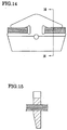
- the V-block has a shape as shown in Figs 14, 15 (Figs. 2a, 2b of Japanese Laid-Open Patent Publication Hei 2-225840). Hitherto, the V-block was manufactured in the manner as follows.
- a plate material of an uniform thickness is punched in a front shape of the V-block to obtain the V-block, and at that time, while thickness of an outer portion of the V-block is left at the uniform thickness, an inner portion of the V-block is press-crushed so that the thickness is reduced gradually toward the innermost portion from a rocking edge.
- the inner portion of the V-block is formed thin stepwise in advance, then a slant surface extending from the rocking edge toward the inner portion is formed by a counter punch.
- V-block as shown in Figs. 14, 15 is manufactured without changing thickness of the plate material partly, since mean depth of the press-crushing at the inner portion of the V-block is large, abrasion of a die is severe to shorten the life of the die and result in high cost.
- the present invention provides a method for manufacturing a V-block of a metal belt type continuously variable transmission having an endless metal belt comprising a thin metal ring assembly formed by thin metal rings piled on each other stratified and many V-blocks supported by the thin metal ring assembly along its circumference, and wound round a drive pulley and a driven pulley for controlling speed change ratio by changing widths of grooves of the pulleys, wherein the V-block is formed by punching a V-belt press material with a main punch and a counter punch; the V-block press material has a section including an outer portion of about uniform width and a tapered inner portion having a slant gently inclined toward an innermost end of the material from a place distant from a rocking edge by a predetermined distance inward; the main punch and the counter punch have front shapes of the substantially same as that of the V-block; and either punch facing the rocking edge has a slant starting at a place corresponding to the rocking edge
- the press-crushed part of the V-block press material is thickest at the beginning point of the taper of the V-block press material and becomes gradually thinner from the beginning point toward the rocking edge, as well as similarly becoming gradually thinner from the beginning point inward. Therefore, mean crushing depth of the press-crushed part of the V-block press material becomes smaller than that of the customary method in which the crushed part becomes gradually thicker from the rocking edge inward. As the result, local surface pressure of the counter punch on press forming can be made low to greatly prolong the life of the press die.
- the inner portion of the V-block since thickness of the inner portion of the V-block does not reduced remarkably compared with thickness of the outer portion, strength and rigidity of the inner portion, which is subjected to strong compressive load by the V-groove of the pulley, is not lowered so largely, so that abrasion of a part of the V-block contacted with the pulley is small, loads allotted to the V-block and the metal ring hardly become unequal by deformation of the saddle surface, and durability of the metal belt and power transmitting efficiency are improved.
- press-crush volume at a portion between the beginning point of the taper and the rocking edge of the V-block press material and press-crush volume at a region inside of the beginning point of the taper of the V-block press material are substantially equal, almost no press reaction force accompanying press forming acts on the punch, relative position of the punch with respect to the die can be maintained exactly, accuracy of shape and size can be improved greatly and no broken surface is produced.
- a die for manufacturing a V-block of a metal belt type continuously variable transmission wherein the die has a front shape of the substantially same as that of the V-block; the die comprises a main punch and a counter punch having parallel surfaces for pinching a V-block press material having a sectional view including an outer portion of about uniform width and a tapered inner portion having a slant gently inclined toward an innermost end of the material from a place distant from a rocking edge by a predetermined distant inward; and either punch of the main and counter punches facing the rocking edge has a slant starting at a place corresponding to the rocking edge and extending inward rising gradually.
- a thin metal ring 1 of a metal belt type continuously variable transmission 0 has a circumference of 660 mm, a width of 9.2 mm and a thickness of 0.18 mm, for example. As shown in Fig. 2, twelve sheets of thin metal rings 1 are piled in direction of thickness closely to form a thin metal ring assembly 2. Many metal V-blocks 3 are supported by a pair of the thin metal ring assemblies 2 to constitute an endless metal belt.
- the endless metal belt 4 is wound round a drive pulley 5 and a driven pulley 6 of the metal belt type continuously variable transmission 0.
- the drive pulley 5 is connected with an internal combustion engine (not shown) through a starting clutch (not shown), and the driven pulley 6 is connected with right and left wheels (not shown) through a gear transmission and a differential gear (not shown) for transmitting power of the internal combustion engine to the wheels.
- the drive pulley 5 and the driven pulley 6 have respective oil chambers (not shown).
- the oil chambers are added with suitably adjusted oil pressure respectively, so that widths of pulley grooves of the drive pulley 5 and the driven pulley 6 is adjusted to give the metal belt type continuously variable transmission an optimum speed ratio.
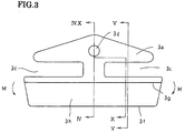
- the metal V-block has a width of 24mm, a height of 13mm and a thickness of 1.5mm.
- an outer portion is shaped like an umbrella and right and left cuts 3c is formed at an intermediate portion.
- a front surface of the metal V-block 3 with respect to its advancing direction is provided with a short columnar projection 3d at an outer portion
- a rear surface of the metal V-block 3 is provided with a hollow 3e corresponding to the short columnar projection 3d at an outer portion.
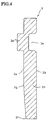
- the rear surface 3b of the metal V-block 3 and the outer portion of the front surface 3a of the metal V-block 3 are flat and parallel with each other.
- inner portion of the front surface 3a of the metal V-block 3 is inclined so that the metal V-block 3 becomes thinner gradually toward an inner edge 3f of the metal V-block 3 from a rocking edge 3g which is positioned at a place distant from the inner edge 3f by 4.2 mm.
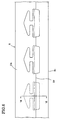
- V-block material 8 as shown in Fig. 7 is formed in advance.
- the V-block material 8 is formed from a long belt-like material having a constant thickness of 5 mm and a constant width of about 40 mm that is larger than the height of the metal V-block 3 (13 mm) for facilitating to hold the belt-like material.
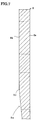
- a surface 8b of the belt-like material 8 is obliquely shaved from an edge line 3d distant from a side edge 3c of the belt-like material by about 17 mm, toward the side edge 3c, so as to form a slant 8e having inclination angle of about 6°.
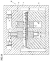
- This V-block material is punched with a punching apparatus 10 as shown in Fig. 10 to obtain the metal V-block 3.
- the punching apparatus 10 has a frame 11, a lower die 12 placed on a lower part of the frame 11, and an upper die 13 fitted in the frame 11 so as to approach and go away from the lower die 12.
- the upper die 13 is driven, up and down, by a die drive hydraulic cylinder 14 provided on an upper part of the frame 11.
- An upper surface 12a of the lower die 12 is formed with a depression 12b of the same shape as (exactly, slightly larger than) the front shape of the metal V-block 3.
- a counter punch 15 is closely fitted in this depression 12b so as to slide up and down.
- a counter punch drive hydraulic cylinder 16 is inserted between the counter punch 15 and a bottom part of the frame 11 to drive the counter punch 15 up and down.
- a lower surface 13a of the upper die 13 is formed with a depression 13b of the same shape as the shape of the depression 12b of the lower die 12.
- a punch 17 so as to slide, up and down.
- a punch drive hydraulic cylinder 18 with a piston 18a penetrating the upper die 13.
- the punch 17 is driven, up and down, by the punch drive hydraulic cylinder 18.
- a short columnar hollow 15b for forming the projection 3d of the metal V-block 3
- a projection 17b for forming the short columnar hollow 3e of the metal V-block 3.
- a slant 15e of about 3.5 degrees. The slant 15e begins at a place 15d distant from an inner edge 15c of the counter punch 15 by 4.2 mm and extends toward the inner edge 15c.
- the v-block material 8 is placed on the lower die 12 and the counter punch 15 as shown in Fig. 10, and die drive hydraulic cylinder 14 and the main punch drive hydraulic cylinder 18 is operated to bring the lower surfaces 13a, 17a of the upper die 13 and the main punch 17 into contact with the surface 8b of the V-block material 8, then the V-block material is pinched by a constant pinching force by keeping oil pressure of the main punch drive hydraulic cylinder 18 and the counter punch drive hydraulic cylinder 16 at a predetermined pressure (Fig. 11). And, the main counter 17 and the counter punch 15 is lowered together to obtain a piece of the metal V-block 3 by the punch processing (Fig. 12).
- the die drive hydraulic cylinder 14, the counter punch drive hydraulic cylinder 16 and the main punch drive hydraulic cylinder 18 are returned to respective positions shown in Fig. 10, then the V-block material 8 is shifted in a direction of width of the metal V-block 3 (longitudinal direction of the V-block material 8) by 50 mm for example, beyond the width (24 mm) of the metal V-block 3, and then the aforementioned punch processing is repeated for mass production.
- the edge line 8d of the V-block material 8 and the rocking edge 3g , which is a slant beginning edge, of the metal V-block 3 are distant from each other by 1.4 mm, and a part of the V-block material 8 crushed by the upper surface of the counter punch 15, which is smeared black in Fig. 8A, has a shape of an isosceles triangle.
- the crush sectional area A of the metal V-block 3 according to the present embodiment shown in Figs. 14, 15 is 0.112295 mm 2
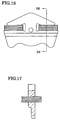
- the crush sectional area A of the V-block shown in Figs. 16, 17 is 0.08522 mm 2
- the crush length L of the metal V-block 3 shown in Figs. 14, 15 is 3.218 mm
- the crush length L of the V-block shown in Figs. 16, 17 is 1.966 mm.
- the mean crush depth A/L as clear from the table of Fig. 19, that of the metal V-block 3 according to the present embodiment is lower than that of the customary V-block shown in Figs. 16, 17. Therefore, according to the present invention, life of the punch is prolonged.
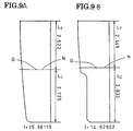
- Fig. 9A shows the inner portion 3h of the metal V-block 3 shown in Figs. 14, 15, and Fig. 9B shows similar inner portion of the customary v-block shown in Figs. 16, 17.
- a portion near the innermost end is made thin compared with the metal V-block 3 of the present embodiment, and therefore moment of inertia of area I of the inner portion 3h with respect to a neutral axis N passing through the center of gravity G is smaller than similar I of the inner portion 3h of the metal V-block 3 of the present embodiment.
Landscapes
- Engineering & Computer Science (AREA)
- Mechanical Engineering (AREA)
- General Engineering & Computer Science (AREA)
- Punching Or Piercing (AREA)
- Forging (AREA)
Abstract
Description
Claims (3)
- A method for manufacturing a V-block of a metal belt type continuously variable transmission having an endless metal belt comprising a thin metal ring assembly formed by thin metal rings piled on each other stratified and many V-blocks supported by the thin metal ring assembly along its circumference, and wound round a drive pulley and a driven pulley for controlling speed change ratio by changing widths of grooves of the pulleys, wherein
said V-block is formed by punching a V-block press material with a main punch and a counter punch;
said V-block press material has a sectional view including an outer portion of about uniform width and a tapered inner portion with a slant gently inclined toward an innermost end of the material from a place distant from a rocking edge by a predetermined distance inward;
said main punch and said counter punch have front shapes of the substantially same as that of said V-block; and
either punch facing said rocking edge has a slant starting at a place corresponding to said rocking edge and extending inward rising gradually. - A method for manufacturing a V-block of a metal belt type continuously variable transmission as claimed in claim 1, wherein press-crush volume at a portion between a beginning point of the taper and said rocking edge of said V-block press material and press-crush volume at a region inside of said beginning point of the taper of the V-block press material are substantially equal.
- A die for manufacturing a V-block of a metal belt type continuously variable transmission, wherein
said die has a front shape of the substantially same as that of said V-block;
said die comprises a main punch and a counter punch having parallel surfaces for punching a V-block press material having a sectional view including an outer portion of about uniform width and a tapered inner portion with a slant gently inclined toward an innermost end of the material from a place distant from a rocking edge by a predetermined distance inward; and
either punch facing said rocking edge has a slant starting at a place corresponding to said rocking edge and extending to inwardly rise gradually.
Applications Claiming Priority (3)
| Application Number | Priority Date | Filing Date | Title |
|---|---|---|---|
| JP2000115729 | 2000-04-17 | ||
| JP2000115729 | 2000-04-17 | ||
| PCT/JP2001/003063 WO2001078919A1 (en) | 2000-04-17 | 2001-04-10 | Method of manufacturing v-block of metallic belt type continuously variable transmission and metal mold for the v-block |
Publications (3)
| Publication Number | Publication Date |
|---|---|
| EP1287924A1 true EP1287924A1 (en) | 2003-03-05 |
| EP1287924A4 EP1287924A4 (en) | 2005-11-30 |
| EP1287924B1 EP1287924B1 (en) | 2006-12-20 |
Family
ID=18627312
Family Applications (1)
| Application Number | Title | Priority Date | Filing Date |
|---|---|---|---|
| EP01919849A Expired - Lifetime EP1287924B1 (en) | 2000-04-17 | 2001-04-10 | Method of manufacturing v-block of metallic belt type continuously variable transmission and metal mold for the v-block |
Country Status (9)
| Country | Link |
|---|---|
| US (1) | US6742373B2 (en) |
| EP (1) | EP1287924B1 (en) |
| JP (1) | JP4132820B2 (en) |
| KR (1) | KR100663312B1 (en) |
| CN (1) | CN1195596C (en) |
| CA (1) | CA2370481C (en) |
| DE (1) | DE60125356T2 (en) |
| TW (1) | TW470830B (en) |
| WO (1) | WO2001078919A1 (en) |
Cited By (3)
| Publication number | Priority date | Publication date | Assignee | Title |
|---|---|---|---|---|
| NL1024530C2 (en) * | 2003-10-14 | 2005-04-15 | Bosch Gmbh Robert | Preventing bursting during a punching process of a transverse element for a push belt for a continuously variable transmission. |
| NL1030702C2 (en) * | 2005-12-19 | 2007-06-20 | Bosch Gmbh Robert | Method for manufacturing a transverse element intended to form part of a push belt for a continuously variable transmission. |
| WO2015101659A1 (en) | 2014-01-02 | 2015-07-09 | Robert Bosch Gmbh | Basic material for a transverse segment for a drive belt for a continuously variable transmission and blanking method using it |
Families Citing this family (19)
| Publication number | Priority date | Publication date | Assignee | Title |
|---|---|---|---|---|
| DE60112176T2 (en) * | 2000-05-26 | 2005-12-29 | Honda Giken Kogyo K.K. | Method and device for punching parts of a belt for continuously variable transmission |
| NL1019639C2 (en) * | 2001-12-21 | 2003-06-24 | Method for forming a link for a push belt for a continuously variable transmission. | |
| DE60116795T2 (en) * | 2001-12-24 | 2006-08-17 | Van Doorne's Transmissie B.V. | WORKPIECE, DRIVE BELTS AND METHOD AND TOOL FOR THIS |
| JP3827005B2 (en) * | 2002-06-12 | 2006-09-27 | アイダエンジニアリング株式会社 | Element manufacturing method for continuously variable transmission belt |
| NL1024614C2 (en) * | 2003-10-24 | 2005-04-27 | Bosch Gmbh Robert | Cutting process for manufacturing a ring, cutting device, ring and push belt provided with a ring. |
| NL1025080C2 (en) * | 2003-12-19 | 2005-06-21 | Bosch Gmbh Robert | Shared mold with at least two mold components. |
| CN102282387B (en) * | 2009-08-28 | 2013-10-16 | 丰田自动车株式会社 | Power transmitting belt and method of manufacturing same |
| JP5710633B2 (en) * | 2010-09-30 | 2015-04-30 | 本田技研工業株式会社 | Workpiece punching device, work punching method, and manufacturing method of continuously variable transmission element |
| NL1039270C2 (en) * | 2011-12-28 | 2013-07-01 | Bosch Gmbh Robert | Divided blanking member for the purpose of blanking transverse elements for use in a drive belt for a continuously variable transmission. |
| US9327339B2 (en) | 2012-02-13 | 2016-05-03 | Aisin Aw Co., Ltd. | Element blanking apparatus and method |
| JP6506062B2 (en) * | 2015-03-24 | 2019-04-24 | 本田技研工業株式会社 | Method of manufacturing metal element for continuously variable transmission |
| EP3175937B8 (en) | 2015-12-02 | 2021-03-03 | Honda Motor Co., Ltd. | Method for producing metal element for continuously variable transmission and metal element for continuously variable transmission |
| JP6396361B2 (en) * | 2016-04-15 | 2018-09-26 | 本田技研工業株式会社 | Method for manufacturing metal element for continuously variable transmission |
| JP6461890B2 (en) * | 2016-11-21 | 2019-01-30 | 本田技研工業株式会社 | Method for manufacturing metal element for continuously variable transmission |
| US11149820B2 (en) * | 2017-03-03 | 2021-10-19 | Aisin Aw Co., Ltd. | Element designing method and power transfer belt |
| CN108799410B (en) | 2017-04-28 | 2020-08-18 | 本田技研工业株式会社 | Manufacturing method of metal element for continuously variable transmission |
| JP6957400B2 (en) * | 2018-03-27 | 2021-11-02 | 本田技研工業株式会社 | Molding method of metal plate material |
| JP6621495B2 (en) | 2018-04-03 | 2019-12-18 | 本田技研工業株式会社 | Metal element for continuously variable transmission and method for manufacturing metal element for continuously variable transmission |
| NL1043501B1 (en) * | 2019-12-10 | 2021-08-31 | Bosch Gmbh Robert | A transverse segment for a drive belt and a drive belt for a continuously variable transmission including the transverse segment and a ring stack |
Family Cites Families (10)
| Publication number | Priority date | Publication date | Assignee | Title |
|---|---|---|---|---|
| NL182128C (en) * | 1979-02-22 | 1988-01-18 | Volvo Car Bv | METHOD FOR PRODUCING FORCE-TRANSMITTING CROSS-TRANSMITTING CROSS-SHEETS |
| JPS63115638A (en) * | 1986-10-31 | 1988-05-20 | Fuji Heavy Ind Ltd | Forming method for element in driving belt for continuously variable transmission |
| NL8700156A (en) * | 1987-01-23 | 1988-08-16 | Doornes Transmissie Bv | DRIVING BELT, CROSS-ELEMENT FOR A DRIVING BELT AND METHOD AND APPARATUS FOR MANUFACTURE THEREOF. |
| JPS63277703A (en) * | 1987-05-11 | 1988-11-15 | Kobe Steel Ltd | Production of metallic block for transmission belt |
| NL8900072A (en) * | 1989-01-12 | 1990-08-01 | Doornes Transmissie Bv | CROSS-ELEMENT FOR A BELT. |
| JP3445832B2 (en) * | 1994-06-28 | 2003-09-08 | 日本発条株式会社 | Method for manufacturing transmission belt block and manufacturing die |
| JPH11309522A (en) * | 1998-04-24 | 1999-11-09 | Honda Motor Co Ltd | Sheet material punching method |
| JP4229532B2 (en) * | 1999-07-05 | 2009-02-25 | 本田技研工業株式会社 | Belt for continuously variable transmission |
| EP1128088B1 (en) * | 2000-02-21 | 2004-04-28 | Honda Giken Kogyo Kabushiki Kaisha | Method and apparatus for blanking elements of belt for continuously variable transmission |
| JP3703678B2 (en) * | 2000-03-06 | 2005-10-05 | 本田技研工業株式会社 | Punching method for continuously variable transmission belt elements |
-
2001
- 2001-04-10 KR KR1020017013929A patent/KR100663312B1/en not_active Expired - Fee Related
- 2001-04-10 JP JP2001576210A patent/JP4132820B2/en not_active Expired - Fee Related
- 2001-04-10 WO PCT/JP2001/003063 patent/WO2001078919A1/en not_active Ceased
- 2001-04-10 EP EP01919849A patent/EP1287924B1/en not_active Expired - Lifetime
- 2001-04-10 CA CA002370481A patent/CA2370481C/en not_active Expired - Fee Related
- 2001-04-10 DE DE60125356T patent/DE60125356T2/en not_active Expired - Lifetime
- 2001-04-10 CN CNB018009654A patent/CN1195596C/en not_active Expired - Fee Related
- 2001-04-10 US US09/926,405 patent/US6742373B2/en not_active Expired - Lifetime
- 2001-04-13 TW TW090108952A patent/TW470830B/en active
Cited By (6)
| Publication number | Priority date | Publication date | Assignee | Title |
|---|---|---|---|---|
| NL1024530C2 (en) * | 2003-10-14 | 2005-04-15 | Bosch Gmbh Robert | Preventing bursting during a punching process of a transverse element for a push belt for a continuously variable transmission. |
| WO2005035163A1 (en) * | 2003-10-14 | 2005-04-21 | Robert Bosch Gmbh | The prevention of formation of burrs in a blanking process of a transverse element for a push belt for a continuously variable transmission |
| NL1030702C2 (en) * | 2005-12-19 | 2007-06-20 | Bosch Gmbh Robert | Method for manufacturing a transverse element intended to form part of a push belt for a continuously variable transmission. |
| WO2007073159A1 (en) * | 2005-12-19 | 2007-06-28 | Robert Bosch Gmbh | Method for manufacturing a transverse element that is destined to be part of a push belt for a continuously variable transmission |
| WO2015101659A1 (en) | 2014-01-02 | 2015-07-09 | Robert Bosch Gmbh | Basic material for a transverse segment for a drive belt for a continuously variable transmission and blanking method using it |
| JP2017501356A (en) * | 2014-01-02 | 2017-01-12 | ローベルト ボツシユ ゲゼルシヤフト ミツト ベシユレンクテル ハフツングRobert Bosch Gmbh | Basic material of transverse segment for drive belt for continuously variable transmission, and punching method using the basic material |
Also Published As
| Publication number | Publication date |
|---|---|
| US6742373B2 (en) | 2004-06-01 |
| CA2370481A1 (en) | 2001-10-25 |
| WO2001078919A1 (en) | 2001-10-25 |
| EP1287924A4 (en) | 2005-11-30 |
| KR20020025865A (en) | 2002-04-04 |
| CN1195596C (en) | 2005-04-06 |
| TW470830B (en) | 2002-01-01 |
| CA2370481C (en) | 2005-08-16 |
| EP1287924B1 (en) | 2006-12-20 |
| US20020138986A1 (en) | 2002-10-03 |
| KR100663312B1 (en) | 2007-01-02 |
| DE60125356T2 (en) | 2007-04-19 |
| JP4132820B2 (en) | 2008-08-13 |
| DE60125356D1 (en) | 2007-02-01 |
| CN1366471A (en) | 2002-08-28 |
Similar Documents
| Publication | Publication Date | Title |
|---|---|---|
| EP1287924B1 (en) | Method of manufacturing v-block of metallic belt type continuously variable transmission and metal mold for the v-block | |
| JPWO2001078919A1 (en) | Manufacturing method of V-block for metal belt type continuously variable transmission and mold therefor | |
| JP5146595B2 (en) | Transmission belt and manufacturing method thereof | |
| EP2425907B1 (en) | Method for manufacturing element for belt of continuously variable transmission | |
| US5125256A (en) | Method of manufacturing outside ring | |
| EP3175937B1 (en) | Method for producing metal element for continuously variable transmission and metal element for continuously variable transmission | |
| US5737955A (en) | Method for inclearing thickness of outer peripheral portion of disc, and method for molding disc member having transmitting portion in outer periphery thereof | |
| CN108799410A (en) | The manufacturing method of contiuously variable transmission hardware | |
| CN108019474A (en) | Buncher hardware and its manufacture method | |
| JP5278560B2 (en) | Belt element for continuously variable transmission and method for manufacturing the same | |
| CN108080499A (en) | The manufacturing method of buncher hardware | |
| KR100346946B1 (en) | Torque Transmitting Member in Automotive Transmission, Method for Forming Spline Teeth, and Apparatus for Forming the Same | |
| JP2019171390A (en) | Molding method for metal plate material | |
| JP4315672B2 (en) | Method for manufacturing element of continuously variable transmission belt | |
| US11506256B2 (en) | Metal element for continuously variable transmission and method of manufacture the same | |
| CN113677451A (en) | Method and apparatus for producing monomer | |
| JP4570209B2 (en) | CVT belt element and manufacturing method thereof | |
| JP2018111132A (en) | Method for manufacturing transverse member for drive belt used for continuously variable transmission | |
| WO2018122399A1 (en) | Method for manufacturing a transverse segment for a drive belt for a continuously variable transmission | |
| JPH02121739A (en) | Manufacture of multistage and multigroove v-pulley | |
| JP6396361B2 (en) | Method for manufacturing metal element for continuously variable transmission | |
| KR20030020159A (en) | A Crown Type Pulley with an Protrusion on an Outer Circumference and Method for Manufacturing the Same | |
| JPH07217722A (en) | Pulley and manufacturing method thereof | |
| JPS5929336B2 (en) | Manufacturing method of metal plate V-pulley | |
| JPS6228036A (en) | Production for multigrooved v pulley with separative belt |
Legal Events
| Date | Code | Title | Description |
|---|---|---|---|
| PUAI | Public reference made under article 153(3) epc to a published international application that has entered the european phase |
Free format text: ORIGINAL CODE: 0009012 |
|
| 17P | Request for examination filed |
Effective date: 20011130 |
|
| AK | Designated contracting states |
Designated state(s): AT BE CH CY DE DK ES FI FR GB GR IE IT LI LU MC NL PT SE TR Kind code of ref document: A1 Designated state(s): AT BE CH CY DE DK ES FI FR GB GR IE IT LI LU MC NL PT SE TR |
|
| RBV | Designated contracting states (corrected) |
Designated state(s): DE FR GB NL |
|
| A4 | Supplementary search report drawn up and despatched |
Effective date: 20051018 |
|
| GRAP | Despatch of communication of intention to grant a patent |
Free format text: ORIGINAL CODE: EPIDOSNIGR1 |
|
| GRAS | Grant fee paid |
Free format text: ORIGINAL CODE: EPIDOSNIGR3 |
|
| GRAA | (expected) grant |
Free format text: ORIGINAL CODE: 0009210 |
|
| AK | Designated contracting states |
Kind code of ref document: B1 Designated state(s): DE FR GB NL |
|
| REG | Reference to a national code |
Ref country code: GB Ref legal event code: FG4D |
|
| REF | Corresponds to: |
Ref document number: 60125356 Country of ref document: DE Date of ref document: 20070201 Kind code of ref document: P |
|
| ET | Fr: translation filed | ||
| PLBE | No opposition filed within time limit |
Free format text: ORIGINAL CODE: 0009261 |
|
| STAA | Information on the status of an ep patent application or granted ep patent |
Free format text: STATUS: NO OPPOSITION FILED WITHIN TIME LIMIT |
|
| 26N | No opposition filed |
Effective date: 20070921 |
|
| PGFP | Annual fee paid to national office [announced via postgrant information from national office to epo] |
Ref country code: FR Payment date: 20090417 Year of fee payment: 9 |
|
| PGFP | Annual fee paid to national office [announced via postgrant information from national office to epo] |
Ref country code: GB Payment date: 20090408 Year of fee payment: 9 |
|
| GBPC | Gb: european patent ceased through non-payment of renewal fee |
Effective date: 20100410 |
|
| REG | Reference to a national code |
Ref country code: FR Ref legal event code: ST Effective date: 20101230 |
|
| PG25 | Lapsed in a contracting state [announced via postgrant information from national office to epo] |
Ref country code: FR Free format text: LAPSE BECAUSE OF NON-PAYMENT OF DUE FEES Effective date: 20100430 |
|
| PG25 | Lapsed in a contracting state [announced via postgrant information from national office to epo] |
Ref country code: GB Free format text: LAPSE BECAUSE OF NON-PAYMENT OF DUE FEES Effective date: 20100410 |
|
| REG | Reference to a national code |
Ref country code: DE Ref legal event code: R084 Ref document number: 60125356 Country of ref document: DE Effective date: 20120209 |
|
| PGFP | Annual fee paid to national office [announced via postgrant information from national office to epo] |
Ref country code: NL Payment date: 20120413 Year of fee payment: 12 |
|
| PGFP | Annual fee paid to national office [announced via postgrant information from national office to epo] |
Ref country code: DE Payment date: 20130403 Year of fee payment: 13 |
|
| REG | Reference to a national code |
Ref country code: NL Ref legal event code: V1 Effective date: 20131101 |
|
| PG25 | Lapsed in a contracting state [announced via postgrant information from national office to epo] |
Ref country code: NL Free format text: LAPSE BECAUSE OF NON-PAYMENT OF DUE FEES Effective date: 20131101 |
|
| REG | Reference to a national code |
Ref country code: DE Ref legal event code: R119 Ref document number: 60125356 Country of ref document: DE |
|
| REG | Reference to a national code |
Ref country code: DE Ref legal event code: R119 Ref document number: 60125356 Country of ref document: DE Effective date: 20141101 |
|
| PG25 | Lapsed in a contracting state [announced via postgrant information from national office to epo] |
Ref country code: DE Free format text: LAPSE BECAUSE OF NON-PAYMENT OF DUE FEES Effective date: 20141101 |