EP1286534A2 - Image-based selection of gamut mapping - Google Patents
Image-based selection of gamut mapping Download PDFInfo
- Publication number
- EP1286534A2 EP1286534A2 EP02254904A EP02254904A EP1286534A2 EP 1286534 A2 EP1286534 A2 EP 1286534A2 EP 02254904 A EP02254904 A EP 02254904A EP 02254904 A EP02254904 A EP 02254904A EP 1286534 A2 EP1286534 A2 EP 1286534A2
- Authority
- EP
- European Patent Office
- Prior art keywords
- gamut mapping
- original image
- gamut
- regions
- image
- Prior art date
- Legal status (The legal status is an assumption and is not a legal conclusion. Google has not performed a legal analysis and makes no representation as to the accuracy of the status listed.)
- Granted
Links
Images




Classifications
-
- H—ELECTRICITY
- H04—ELECTRIC COMMUNICATION TECHNIQUE
- H04N—PICTORIAL COMMUNICATION, e.g. TELEVISION
- H04N1/00—Scanning, transmission or reproduction of documents or the like, e.g. facsimile transmission; Details thereof
- H04N1/46—Colour picture communication systems
- H04N1/56—Processing of colour picture signals
- H04N1/60—Colour correction or control
- H04N1/6058—Reduction of colour to a range of reproducible colours, e.g. to ink- reproducible colour gamut
-
- G—PHYSICS
- G06—COMPUTING OR CALCULATING; COUNTING
- G06T—IMAGE DATA PROCESSING OR GENERATION, IN GENERAL
- G06T11/00—Two-dimensional [2D] image generation
- G06T11/10—Texturing; Colouring; Generation of textures or colours
Definitions
- the present invention relates to gamut mapping of colors in a color image, and in particular relates to selection of different gamut mappings for different regions of an image based on a spatial frequency analysis of the image.
- Gamut mapping is a well-known procedure by which colors in a color image that are not reproducible by an output device are mapped to reproducible colors, while preserving the perception of good color fidelity and colorfulness.
- gamut mapping algorithms have been proposed, and it is known that some types of color images are gamut-mapped better with some gamut mapping algorithms than others. For example, it is known that computer graphic images having only a few highly saturated colors, such as might be found in a presentation, are gamut mapped more accurately by preserving saturation rather than by preserving hue. On the other hand, for natural scene photographic images, better gamut-mapped results are obtained by preserving hue and hue gradation. It has therefore been considered to analyze an image as a whole, or analyze each region in an image, so as to identify images or regions thereof for which different gamut mapping algorithms should be applied based on content.
- the invention is gamut mapping of an original image by one or more of plural different gamut mapping algorithms, in which spatial frequency content of the original image is analyzed, regions of the original image are associated with one of the plural gamut mapping algorithms based on the spatial frequency analysis, and each region associated with a gamut mapping algorithm is gamut mapped using the associated gamut mapping algorithm so as to produce a gamut mapped image of the original image.
- regions of the image are associated with one of the plural gamut mapping algorithms by segregating the image into busy regions and smooth regions based on the spatial frequency analysis.
- Gamut mapping proceeds by a first gamut mapping algorithm (such as a clipping algorithm) for smooth regions, and by a second gamut mapping algorithm (such as a compression algorithm) for busy regions.
- one or more spatial frequency mask may be constructed, which mask regions for gamut mapping by the first algorithm and regions for gamut mapping by the second algorithm.
- Spatial frequency analysis may proceed by known or hereafter developed analysis tools such as discrete cosine transform, discrete Fourier transform, or discrete wavelet transform. Regions of the original image are associated with one of the plural gamut mapping algorithms based on coefficients from such transforms.
- the original image may be transformed into a color space more suitable for gamut mapping analysis, such as a perceptual color space like CIEL*a*b* space or a viewing condition independent color space like Jch color space (as defined in CIECAM97s).
- Figures 5, 8 and 9 have been reproduced with halftone dots even though they are intended to represent fully grayscale images.
- FIG. 1 is a view showing the outward appearance of representative computing equipment 10 which includes image-based gamut mapping according to an embodiment of the invention.
- Computing equipment 10 includes host processor 11 which comprises a personal computer (hereinafter "PC") preferably having a windowing operating system such as Microsoft Windows, Xwindows or MacIntosh operating systems.
- PC personal computer
- color monitor 12 including display screen 14, keyboard 15 for entering text data and user commands, and pointing device 16.
- Pointing device 16 preferably comprises a mouse, for pointing, selecting and manipulating objects displayed on display screen 14.
- Computing equipment 10 includes a computer-readable memory medium such as a fixed disk 17 and/or floppy disk drive 19 and/or CDROM drive 20.
- Such computer readable memory media allow computing equipment 10 to access information such as image data, computer executable process steps, application programs, and the like, stored on removable and non-removable memory media.
- network access 21 allows computing equipment 10 to acquire information, images and application programs from other sources, such as a local area network or the Internet, or from digital cameras or digital video cameras.
- Scanner 22 scans original images such as original color photographs or color documents to provide image information to computing equipment 10.
- Printer 24 is a color output device such as an ink jet printer or a color laser beam printer.
- FIG. 2 is a detailed block diagram showing the internal architecture of PC 11.
- PC 11 includes central processing unit (“CPU”) 25 that interfaces with computer bus 26. Also interfacing with computer bus 26 are fixed disk 17, network interface 27 for network access 21, random access memory (“RAM”) 29 for use as main memory, read only memory (“ROM”) 30, floppy disk interface 31, CDROM interface 32, display interface 34 to monitor 12, keyboard interface 36 to keyboard 15, mouse interface 37 to pointing device 16, scanner interface 39 to scanner 22, and printer interface 40 to printer 24.
- CPU central processing unit
- RAM random access memory
- ROM read only memory
- Main memory 29 interfaces with computer bus 26 so as to provide RAM storage to CPU 25 during execution of software programs such as the operating system, application programs, and device drivers. More specifically, CPU 25 loads computer-executable process steps from disk 17 or other memory media into a region of main memory 29, and thereafter executes the stored process steps from main memory 29 in order to execute software programs. Data such as color images can be stored in main memory 29, where the data can be accessed by CPU 25 during execution.
- fixed disk 17 contains a window operating system 41, application programs 42 such as application programs that manipulate, obtain and print color images, device drivers 44 such as printer driver 45, and a color management module 46 which includes image-based gamut mapping according to the embodiment of the invention.
- application programs 42 such as application programs that manipulate, obtain and print color images
- device drivers 44 such as printer driver 45
- color management module 46 which includes image-based gamut mapping according to the embodiment of the invention.
- Image-based gamut mapping according to an embodiment of the invention is preferably implemented according to a color management module such as that shown at 46.
- Color management module 46 may be implemented as a stand-alone software application program, but more preferably is implemented as part of an output device driver such as printer driver 45. It is also possible to implement a color management module which includes image-based gamut mapping according to the invention, as a dynamic link library (“DLL”), or as a plug-in to other application programs such as image manipulation programs like Adobe Photoshop.
- DLL dynamic link library
- FIG. 3 is a block diagram showing a preferred implementation of image-based gamut mapping embodied in color management module 46.
- source image data is provided to color management module 46 which processes the source image data 50 so as to generate destination image data 51.
- the source image data 50 is image data in device dependent coordinates, such as RGB image data from scanner 22.
- Destination image data 51 is image data in destination device coordinates, such as CMYK coordinates for printer 24.
- source image data 50 is transformed with the source device transform at forward transform 52, so as to yield image data in a viewing condition independent color space, such as CIEXYZ or CIEL*a*b* space.
- a viewing condition independent color space such as CIEXYZ or CIEL*a*b* space.
- the transformed image data is converted with an appearance model 54 so as to obtain image data in a perceptual color space such as Jch color space, or other profile connection space. While in the perceptual color space, the image data is subjected to gamut mapping, and in particular is subjected to image-based gamut mapping according to the invention at 55. Thereafter, the gamut-mapped image data is converted through inverse appearance model 56 so as to yield image data in a viewing condition independent color space, and thereafter is transformed with an inverse device transform 57 for the destination device, so as to yield image data in destination device coordinates.
- an appearance model 54 so as to obtain image data in a perceptual color space such as Jch color space, or other profile connection space. While in the perceptual color space, the image data is subjected to gamut mapping, and in particular is subjected to image-based gamut mapping according to the invention at 55. Thereafter, the gamut-mapped image data is converted through inverse appearance model 56 so as to yield image data in a viewing condition independent color space, and thereafter is transformed
- Figure 4 is a detailed flow diagram for explaining gamut mapping according to an embodiment of the invention.
- the process steps shown in Figure 4 operate to analyze spatial frequency content of the original image, to associate regions of the original image with one of plural gamut mapping algorithms based on the analysis of spatial frequency content, and to gamut-map each region associated with a gamut mapping algorithm using the associated gamut mapping algorithm so as to produce a gamut-mapped image of the original image.
- the process steps shown in Figure 4 illustrate construction of a spatial mask which, based on a threshold test for values in the spatial mask, masks regions of the original image for gamut mapping by a first gamut mapping algorithm and regions of the original image for gamut mapping by a second gamut mapping algorithm.
- step S401 converts the original image to a perceptually uniform space if such a conversion is needed.
- the illustrated embodiment shows image based gamut mapping 55 in the context of a color management module 46, it is possible to implement an embodiment of the invention as stand-alone gamut mapping. In such circumstances, it is preferred to transform the input image into a perceptually uniform color space. Jch color space is preferred, but other color spaces such as CIEL*a*b* space are acceptable.
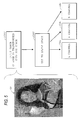
- FIG. 5 is a view for explaining the conversion of step S401.
- an original image 58 sized in this example at 512x640 pixels, is transformed from RGB space to XYZ space in step s501.
- Step S502 transforms to L*a*b* space, so as to yield an L*-channel color component at 59a, an a*-channel color component at 59b, and a b*-channel color component at 59c.
- step S402 analyzes spatial frequency content by performing wavelet decomposition on each component of the converted image. That is, in a situation where step S401 converts the input image to CIEL*a*b* space, then step S402 performs wavelet decomposition on each of the L*, the a* and the b* components of the converted image.
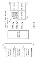
- FIG. 6 shows wavelet decomposition in more detail.
- wavelet decomposition is performed so as to result in recursive representation of the image created by executing a sub-sampling filter on the image data.
- six levels of wavelet data are obtained, with the data taking on values between zero and 2 32 in accordance with image content.
- the six levels are level zero through level five.
- the decomposition of level five data consists of three of four bands that each are N/2 x M/2 in size, for an original image sized NxM. As shown in Figure 6, these three bands are L*a*b* labelled HH at reference numeral 60, LH at reference numeral 61 and HL at reference numeral 62.
- LL band refers to vertically high or low and horizontally high or low pass for the filter that creates these bands.
- a fourth LL band indicated generally at 63, consists of all of level four through level zero data.
- level four data consists of three of four bands that are N/4 x M/4 in size and are L*a*b* labelled respectively HH, LH and HL.
- the LL band is further divided into level three through level zero data. Level three data is subdivided in the same manner as levels above it; level two data and below are not shown in Figure 6 for purposes of clarity.
- steps S403 and S404 operate to construct a spatial mask which masks regions of the original image for gamut mapping by different ones of plural different gamut mapping algorithms.
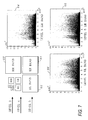
- coefficients from the wavelet decomposition performed in step S402 are rectangularized by normalizing the coefficients and then plotting the coefficients in row and column order. This is illustrated in more detail in Figures 7 and 8.
- wavelet decomposition has resulted in coefficient data shown at 64 for HH band 60, at 65 for LH band 61, and at 66 for HL band 62.
- Each of the coefficient plots shown at 64, 65 and 66 shows coefficient value in the vertical axis as a function of coefficient number in the horizontal axis.
- the original image was sized at 640x512 pixels; thus, each of the HH band 60, the LH band 61 and the HL band 62 is sized at 256x320, resulting in 81,920 coefficients in each band, as shown in the plots at 64, 65 and 66.
- the data in each of these plots is normalized independently of the other plots, using a linear mapping that results in the minimum coefficient value being mapped to a value of zero, and the maximum coefficient value being mapped to a value of 255. Histogram analysis many be used to facilitate normalization.
- the coefficient data is rectangularized by plotting the coefficients in a matrix array sized to the size of the band in question. Thus, since level five data is being considered, the coefficient data is plotted in an array sized 256x320, yielding the rectangularized coefficients shown respectively at 67, 68 and 69.
- Such rectangularized coefficient data is obtained for each level of data, from level zero through level 5, and for each component (that is, for the L* component, the a* component and the b* component in the case of image conversion to CIEL*a*b* space in step S401).
- step S401 combines rectangularized coefficient data from the levels so as to construct an image mask.
- Figure 9 shows rectangularized coefficient data for the L* component in CIEL*a*b* space.
- Figure 9 shows rectangularized components 67, 68 and 69 for level five HH data, HL data and LH data, respectively, as explained above in connection with Figure 8.
- Figure 9 shows rectangularized coefficient data for level five LL data 70, which as explained in connection with Figure 6 consists of all of levels four through level zero data, each with progressively smaller image size.
- a spatial mask 71 is constructed from the rectangularized coefficient data.
- the spatial mask is the same size (MxN) as the original, which in this example means that the spatial mask is 512x640 pixels.
- one pixel from each of the level five HH, LH and HL data is extracted from corresponding pixel positions in each of the HH, LH and HL rectangularized coefficient data, and each such pixel is inserted into three of the four pixels in a small 2x2 grid 72 at a corresponding position in the spatial mask.
- the fourth pixel in the 2x2 grid is obtained starting from level zero data in the level five band LL data at 70, working up through each of level one through level four, so as to obtain a value for the fourth pixel in the 2x2 grid.
- the process is repeated for each corresponding 2x2 pixel grid in spatial mask 71.
- One such method involves a simple average of the normalized coefficient data from each of the HH, HL and LH bands, while ignoring all data from the LL band 70.
- Other methods that have been found to yield acceptable results involve combinations of methods between the two extremes of ignoring all level four through level zero data, and using all level four through level zero data.
- a final spatial mask is obtained by combining the spatial masks obtained in accordance with the procedure described for Figure 9 but for each of the L* component, the a* component and the b* component (in the case of the CIE L*a*b* space).
- the combination is conducted by a weighted Euclidean metric formula, as follows.
- Each value V in array 72 of Figure 9 that is used to build the mask is actually the result of the square root of the sum of the weighted squares of L*, a* and b* wavelet coefficient values (rectangularized and normalized as described before).
- V [( ⁇ L*) ⁇ 2 + ( ⁇ a*) ⁇ 2 + ( ⁇ b*) ⁇ 2] ⁇ (1 ⁇ 2)
- L*, a*, and b* are actually the level/band normalized coefficients obtained form L*, a*, and b* input data
- the constants ⁇ , ⁇ , and ⁇ are between 0 and 1, and their values are adjusted in dependence on image class.
- Acceptable results have also been obtained by employing a spatial mask constructed solely in accordance with the L* component only, or by a spatial mask constructed from a mathematical pixel-for-pixel average of the values obtained for the L* component, the a* component and the b* component.
- step S406 uses the spatial mask to associate regions of the original image with one of plural gamut mapping algorithms.
- two gamut mapping algorithms are used; a clipping gamut mapping algorithms and a compression gamut mapping algorithms.
- the clipping gamut mapping algorithm is more suitable for regions of an image of low spatial frequency content, because the clipping gamut mapping algorithm preserves hue and saturation as much as possible although it loses detail.
- the compression gamut mapping algorithm is more suitable to regions of the image with higher spatial frequency content, since it tends to preserve high levels of detail, although it results in colors that appear more "washed out”.
- a pixel-by-pixel inspection is made of the values of the spatial mask.
- the corresponding pixel in the original image is associated with the clipping gamut mapping algorithm.
- the corresponding pixels in the original image are associated with the compression gamut mapping algorithm. Gamut mapping is then performed on each pixel of the original image associated with a gamut mapping algorithm, using the associated gamut mapping algorithm, so as to produce a gamut mapped image of the original.
- step S406 uses the spatial mask to select between only two gamut mapping algorithms, more than two gamut mapping algorithms are possible
- a selection can be made from three or more gamut mapping algorithms, based on a range of values for the pixels in the spatial mask, with the gamut mapping algorithms each being tailored for a specific range of spatial frequency content.
- step S406 can be modified to operate such that pixels in a particular spatial frequency range are not gamut mapped at all.
Landscapes
- Engineering & Computer Science (AREA)
- Physics & Mathematics (AREA)
- General Physics & Mathematics (AREA)
- Theoretical Computer Science (AREA)
- Multimedia (AREA)
- Signal Processing (AREA)
- Image Processing (AREA)
- Facsimile Image Signal Circuits (AREA)
- Color, Gradation (AREA)
- Color Image Communication Systems (AREA)
Abstract
Description
- The present invention relates to gamut mapping of colors in a color image, and in particular relates to selection of different gamut mappings for different regions of an image based on a spatial frequency analysis of the image.
- Gamut mapping is a well-known procedure by which colors in a color image that are not reproducible by an output device are mapped to reproducible colors, while preserving the perception of good color fidelity and colorfulness.
- Many different gamut mapping algorithms have been proposed, and it is known that some types of color images are gamut-mapped better with some gamut mapping algorithms than others. For example, it is known that computer graphic images having only a few highly saturated colors, such as might be found in a presentation, are gamut mapped more accurately by preserving saturation rather than by preserving hue. On the other hand, for natural scene photographic images, better gamut-mapped results are obtained by preserving hue and hue gradation. It has therefore been considered to analyze an image as a whole, or analyze each region in an image, so as to identify images or regions thereof for which different gamut mapping algorithms should be applied based on content.
- It has heretofore been difficult, however, to identify content of an image or regions thereof, so as to select an appropriate gamut mapping algorithm. In particular, classification of objects in an image, or classification of the image itself, often depends on artificial and/or empirical rules which through trial and error have been found to work on some images, but which do not work on all.
- It is therefore an object of the invention to address the foregoing, by applying different gamut mapping algorithms to different regions of an original image based on spatial frequency content of the original image.
- Thus, in one aspect, the invention is gamut mapping of an original image by one or more of plural different gamut mapping algorithms, in which spatial frequency content of the original image is analyzed, regions of the original image are associated with one of the plural gamut mapping algorithms based on the spatial frequency analysis, and each region associated with a gamut mapping algorithm is gamut mapped using the associated gamut mapping algorithm so as to produce a gamut mapped image of the original image. In preferred embodiments, regions of the image are associated with one of the plural gamut mapping algorithms by segregating the image into busy regions and smooth regions based on the spatial frequency analysis. Gamut mapping proceeds by a first gamut mapping algorithm (such as a clipping algorithm) for smooth regions, and by a second gamut mapping algorithm (such as a compression algorithm) for busy regions. In many embodiments, one or more spatial frequency mask may be constructed, which mask regions for gamut mapping by the first algorithm and regions for gamut mapping by the second algorithm.
- Spatial frequency analysis may proceed by known or hereafter developed analysis tools such as discrete cosine transform, discrete Fourier transform, or discrete wavelet transform. Regions of the original image are associated with one of the plural gamut mapping algorithms based on coefficients from such transforms. In addition, the original image may be transformed into a color space more suitable for gamut mapping analysis, such as a perceptual color space like CIEL*a*b* space or a viewing condition independent color space like Jch color space (as defined in CIECAM97s).
- Because different gamut mapping algorithms are associated with different regions of the original based on spatial frequency analysis of the content of the original image, it is possible to select gamut mapping algorithms that are more accurately tuned to specific spatial frequency content of the original. Thus, better gamut mapping results, inasmuch as spatial frequency analysis is defined more concretely in mathematics, and is less dependent on artificial rules of object classification as in the prior art. In particular, because regions are defined by spatial frequency analysis, as are the masks constructed therefrom, the regions need not follow any preconceived notions of objects in an image, or of their boundaries. For example, prior art image classifiers might successfully identify the image of a person in a natural scene photographic image, and segregate the person's image as a separate object. The invention, on the other hand, might identify several different regions in the person's image, such as hair (which is textured), face (which is smooth), clothing, etc., with different gamut mapping algorithms being applied against different regions.
- This brief summary has been provided so that the nature of the invention may be understood quickly. A more complete understanding of the invention can be obtained by reference to the following detailed description of the preferred embodiment thereof which is described by way of example only with reference to the attached drawings in which:
- Figure 1 is a view illustrating the outward appearance of computing equipment embodying the present invention;
- Figure 2 is a detailed block diagram of the computing equipment shown in Figure 1;
- Figure 3 is a functional block diagram showing a color management module implementing image-based selection of gamut mapping according to an embodiment of the invention;
- Figure 4 is a detailed flow diagram for explaining an embodiment of the invention;
- Figure 5 is a view for explaining color space transformation;
- Figure 6 is a view for explaining wavelet decomposition;
- Figures 7 and 8 are views for explaining normalization of wavelet coefficients and rectangularization of the normalized coefficients; and
- Figure 9 is a view for explaining construction of a spatial mask.
-
- To conform with formal requirements for patent drawings, Figures 5, 8 and 9 have been reproduced with halftone dots even though they are intended to represent fully grayscale images.
- Figure 1 is a view showing the outward appearance of
representative computing equipment 10 which includes image-based gamut mapping according to an embodiment of the invention.Computing equipment 10 includeshost processor 11 which comprises a personal computer (hereinafter "PC") preferably having a windowing operating system such as Microsoft Windows, Xwindows or MacIntosh operating systems. Provided withcomputing equipment 10 arecolor monitor 12 includingdisplay screen 14,keyboard 15 for entering text data and user commands, and pointingdevice 16.Pointing device 16 preferably comprises a mouse, for pointing, selecting and manipulating objects displayed ondisplay screen 14. -
Computing equipment 10 includes a computer-readable memory medium such as a fixeddisk 17 and/orfloppy disk drive 19 and/orCDROM drive 20. Such computer readable memory media allowcomputing equipment 10 to access information such as image data, computer executable process steps, application programs, and the like, stored on removable and non-removable memory media. In addition,network access 21 allowscomputing equipment 10 to acquire information, images and application programs from other sources, such as a local area network or the Internet, or from digital cameras or digital video cameras. -
Scanner 22 scans original images such as original color photographs or color documents to provide image information to computingequipment 10.Printer 24 is a color output device such as an ink jet printer or a color laser beam printer. - Figure 2 is a detailed block diagram showing the internal architecture of
PC 11. As shown in Figure 2, PC 11 includes central processing unit ("CPU") 25 that interfaces withcomputer bus 26. Also interfacing withcomputer bus 26 are fixeddisk 17,network interface 27 fornetwork access 21, random access memory ("RAM") 29 for use as main memory, read only memory ("ROM") 30,floppy disk interface 31,CDROM interface 32,display interface 34 tomonitor 12,keyboard interface 36 tokeyboard 15,mouse interface 37 to pointingdevice 16,scanner interface 39 toscanner 22, andprinter interface 40 toprinter 24. -
Main memory 29 interfaces withcomputer bus 26 so as to provide RAM storage toCPU 25 during execution of software programs such as the operating system, application programs, and device drivers. More specifically,CPU 25 loads computer-executable process steps fromdisk 17 or other memory media into a region ofmain memory 29, and thereafter executes the stored process steps frommain memory 29 in order to execute software programs. Data such as color images can be stored inmain memory 29, where the data can be accessed byCPU 25 during execution. - As also shown in Figure 2,
fixed disk 17 contains awindow operating system 41,application programs 42 such as application programs that manipulate, obtain and print color images,device drivers 44 such asprinter driver 45, and acolor management module 46 which includes image-based gamut mapping according to the embodiment of the invention. - Image-based gamut mapping according to an embodiment of the invention is preferably implemented according to a color management module such as that shown at 46.
Color management module 46 may be implemented as a stand-alone software application program, but more preferably is implemented as part of an output device driver such asprinter driver 45. It is also possible to implement a color management module which includes image-based gamut mapping according to the invention, as a dynamic link library ("DLL"), or as a plug-in to other application programs such as image manipulation programs like Adobe Photoshop. - Figure 3 is a block diagram showing a preferred implementation of image-based gamut mapping embodied in
color management module 46. As shown in Figure 3, source image data is provided tocolor management module 46 which processes thesource image data 50 so as to generatedestination image data 51. Thesource image data 50 is image data in device dependent coordinates, such as RGB image data fromscanner 22.Destination image data 51 is image data in destination device coordinates, such as CMYK coordinates forprinter 24. Internally ofcolor management module 46,source image data 50 is transformed with the source device transform atforward transform 52, so as to yield image data in a viewing condition independent color space, such as CIEXYZ or CIEL*a*b* space. The transformed image data is converted with anappearance model 54 so as to obtain image data in a perceptual color space such as Jch color space, or other profile connection space. While in the perceptual color space, the image data is subjected to gamut mapping, and in particular is subjected to image-based gamut mapping according to the invention at 55. Thereafter, the gamut-mapped image data is converted throughinverse appearance model 56 so as to yield image data in a viewing condition independent color space, and thereafter is transformed with an inverse device transform 57 for the destination device, so as to yield image data in destination device coordinates. - Figure 4 is a detailed flow diagram for explaining gamut mapping according to an embodiment of the invention. Briefly, the process steps shown in Figure 4 operate to analyze spatial frequency content of the original image, to associate regions of the original image with one of plural gamut mapping algorithms based on the analysis of spatial frequency content, and to gamut-map each region associated with a gamut mapping algorithm using the associated gamut mapping algorithm so as to produce a gamut-mapped image of the original image. In addition, the process steps shown in Figure 4 illustrate construction of a spatial mask which, based on a threshold test for values in the spatial mask, masks regions of the original image for gamut mapping by a first gamut mapping algorithm and regions of the original image for gamut mapping by a second gamut mapping algorithm.
- In more detail, step S401 converts the original image to a perceptually uniform space if such a conversion is needed. In particular, although the illustrated embodiment shows image based
gamut mapping 55 in the context of acolor management module 46, it is possible to implement an embodiment of the invention as stand-alone gamut mapping. In such circumstances, it is preferred to transform the input image into a perceptually uniform color space. Jch color space is preferred, but other color spaces such as CIEL*a*b* space are acceptable. - Figure 5 is a view for explaining the conversion of step S401. As shown in Figure 5, an
original image 58, sized in this example at 512x640 pixels, is transformed from RGB space to XYZ space in step s501. Step S502 transforms to L*a*b* space, so as to yield an L*-channel color component at 59a, an a*-channel color component at 59b, and a b*-channel color component at 59c. - After conversion of the image to a perceptually uniform color space, spatial frequency content of the original image is analyzed. In the context of this embodiment of the invention, step S402 analyzes spatial frequency content by performing wavelet decomposition on each component of the converted image. That is, in a situation where step S401 converts the input image to CIEL*a*b* space, then step S402 performs wavelet decomposition on each of the L*, the a* and the b* components of the converted image.
- Figure 6 shows wavelet decomposition in more detail. For each
channel reference numeral 60, LH atreference numeral 61 and HL atreference numeral 62. "H" and "L" refer to vertically high or low and horizontally high or low pass for the filter that creates these bands. In addition, a fourth LL band, indicated generally at 63, consists of all of level four through level zero data. Thus, as seen in Figure 6, level four data consists of three of four bands that are N/4 x M/4 in size and are L*a*b* labelled respectively HH, LH and HL. The LL band is further divided into level three through level zero data. Level three data is subdivided in the same manner as levels above it; level two data and below are not shown in Figure 6 for purposes of clarity. - Reverting to Figure 4, steps S403 and S404 operate to construct a spatial mask which masks regions of the original image for gamut mapping by different ones of plural different gamut mapping algorithms. First, in step S403, coefficients from the wavelet decomposition performed in step S402 are rectangularized by normalizing the coefficients and then plotting the coefficients in row and column order. This is illustrated in more detail in Figures 7 and 8.
- Thus, as shown in Figure 7 for a representative image, wavelet decomposition has resulted in coefficient data shown at 64 for
HH band 60, at 65 forLH band 61, and at 66 forHL band 62. Each of the coefficient plots shown at 64, 65 and 66 shows coefficient value in the vertical axis as a function of coefficient number in the horizontal axis. In this example, the original image was sized at 640x512 pixels; thus, each of theHH band 60, theLH band 61 and theHL band 62 is sized at 256x320, resulting in 81,920 coefficients in each band, as shown in the plots at 64, 65 and 66. In Figure 8, the data in each of these plots is normalized independently of the other plots, using a linear mapping that results in the minimum coefficient value being mapped to a value of zero, and the maximum coefficient value being mapped to a value of 255. Histogram analysis many be used to facilitate normalization. After normalization, the coefficient data is rectangularized by plotting the coefficients in a matrix array sized to the size of the band in question. Thus, since level five data is being considered, the coefficient data is plotted in an array sized 256x320, yielding the rectangularized coefficients shown respectively at 67, 68 and 69. Such rectangularized coefficient data is obtained for each level of data, from level zero throughlevel 5, and for each component (that is, for the L* component, the a* component and the b* component in the case of image conversion to CIEL*a*b* space in step S401). - Reverting to Figure 4, step S401 combines rectangularized coefficient data from the levels so as to construct an image mask. This process is shown in more detail in Figure 9 which shows rectangularized coefficient data for the L* component in CIEL*a*b* space. Figure 9 shows
rectangularized components LL data 70, which as explained in connection with Figure 6 consists of all of levels four through level zero data, each with progressively smaller image size. Aspatial mask 71 is constructed from the rectangularized coefficient data. The spatial mask is the same size (MxN) as the original, which in this example means that the spatial mask is 512x640 pixels. To construct the spatial mask, one pixel from each of the level five HH, LH and HL data is extracted from corresponding pixel positions in each of the HH, LH and HL rectangularized coefficient data, and each such pixel is inserted into three of the four pixels in asmall 2x2 grid 72 at a corresponding position in the spatial mask. The fourth pixel in the 2x2 grid is obtained starting from level zero data in the level five band LL data at 70, working up through each of level one through level four, so as to obtain a value for the fourth pixel in the 2x2 grid. The process is repeated for each corresponding 2x2 pixel grid inspatial mask 71. - While this embodiment obtains the fourth pixel in the 2x2 grid by working from level zero data up through level four data for the level five band LL coefficients at 70, acceptable results have been obtained with different methods for obtaining the fourth pixel. One such method involves a simple average of the normalized coefficient data from each of the HH, HL and LH bands, while ignoring all data from the
LL band 70. Other methods that have been found to yield acceptable results involve combinations of methods between the two extremes of ignoring all level four through level zero data, and using all level four through level zero data. - A final spatial mask is obtained by combining the spatial masks obtained in accordance with the procedure described for Figure 9 but for each of the L* component, the a* component and the b* component (in the case of the CIE L*a*b* space). The combination is conducted by a weighted Euclidean metric formula, as follows. Each value V in
array 72 of Figure 9 that is used to build the mask, is actually the result of the square root of the sum of the weighted squares of L*, a* and b* wavelet coefficient values (rectangularized and normalized as described before). The formula is: - Acceptable results have also been obtained by employing a spatial mask constructed solely in accordance with the L* component only, or by a spatial mask constructed from a mathematical pixel-for-pixel average of the values obtained for the L* component, the a* component and the b* component.
- Reverting to Figure 4, step S406 uses the spatial mask to associate regions of the original image with one of plural gamut mapping algorithms. In this embodiment, two gamut mapping algorithms are used; a clipping gamut mapping algorithms and a compression gamut mapping algorithms. The clipping gamut mapping algorithm is more suitable for regions of an image of low spatial frequency content, because the clipping gamut mapping algorithm preserves hue and saturation as much as possible although it loses detail. On the other hand, the compression gamut mapping algorithm is more suitable to regions of the image with higher spatial frequency content, since it tends to preserve high levels of detail, although it results in colors that appear more "washed out". Thus, in step S406, a pixel-by-pixel inspection is made of the values of the spatial mask. For those pixels of the spatial mask that exceed a predesignated threshold, indicating a low spatial frequency content, the corresponding pixel in the original image is associated with the clipping gamut mapping algorithm. On the other hand, for those pixels in the spatial mask whose value does not exceed the predesignated threshold, indicating a high spatial frequency content, corresponding pixels in the original image are associated with the compression gamut mapping algorithm. Gamut mapping is then performed on each pixel of the original image associated with a gamut mapping algorithm, using the associated gamut mapping algorithm, so as to produce a gamut mapped image of the original.
- Although step S406 uses the spatial mask to select between only two gamut mapping algorithms, more than two gamut mapping algorithms are possible For example, a selection can be made from three or more gamut mapping algorithms, based on a range of values for the pixels in the spatial mask, with the gamut mapping algorithms each being tailored for a specific range of spatial frequency content.
- Likewise, although the foregoing embodiment results in the association of exactly one gamut mapping algorithm for each and every pixel of the original image, step S406 can be modified to operate such that pixels in a particular spatial frequency range are not gamut mapped at all.
- The invention has been described with respect to particular illustrative embodiments. It is to be understood that the invention is not limited to the above-described embodiments and that various changes and modifications may be made by those of ordinary skill in the art without departing from the scope of the invention.
Claims (23)
- A method for gamut mapping an original image using at least one of plural different gamut mapping algorithms, said method comprising the steps of:analyzing spatial frequency content of the original image;associating regions of the original image with one of the plural gamut mapping algorithms based on the analysis of spatial frequency content; andgamut mapping each region associated with a gamut mapping algorithm using the associated gamut mapping algorithm so as to produce a gamut mapped image of the original image.
- A method according to Claim 1, wherein said associating step includes the step of constructing one or more spatial masks which mask regions of the original image for gamut mapping by a first gamut mapping algorithm and which mask regions of the original image for gamut mapping by a second gamut mapping algorithm.
- A method according to Claim 1, wherein said step of associating includes the step of segregating regions of the original image into busy regions and smooth regions.
- A method according to Claim 3, wherein said associating step includes the step of constructing one or more spatial masks which mask regions of the original image for gamut mapping by a first gamut mapping algorithm and which mask regions of the original image for gamut mapping by a second gamut mapping algorithm.
- A method according to Claim 3, wherein said step of gamut mapping includes gamut mapping by a first gamut mapping algorithm for smooth regions and gamut mapping by a second gamut mapping algorithm for busy regions.
- A method according to Claim 5, wherein said associating step includes the step of constructing one or more spatial masks which mask regions of the original image for gamut mapping by a first gamut mapping algorithm and which mask regions of the original image for gamut mapping by a second gamut mapping algorithm.
- A method according to claim 4, wherein the first gamut mapping algorithm is a clipping algorithm and wherein said second gamut mapping algorithm is a compression algorithm.
- A method according to Claim 7, wherein said associating step includes the step of constructing one or more spatial masks which mask regions of the original image for gamut mapping by a first gamut mapping algorithm and which mask regions of the original image for gamut mapping by a second gamut mapping algorithm.
- A method according to Claim 1, wherein said analyzing step uses a spatial frequency analysis tool selected from the group consisting of discrete cosine transform, discrete Fourier transform, and discrete wavelet transform.
- A method according to Claim 9, wherein said associating step associates regions of the original image with one of the plural gamut mapping algorithms based on coefficients derived in said spatial frequency analysis tool.
- A method according to Claim 1, further comprising the step of transforming the original image into a perceptual color space.
- A method according to Claim 11, further comprising the step of constructing one or more spatial masks based on individual ones of the channels in the perceptual color space, and wherein said associating step associates regions of the original image with one of the plural gamut mapping algorithms based on a pre-designated threshold value in the spatial masks.
- A method according to Claim 12, wherein said analyzing step produces frequency-related coefficients, and wherein said constructing step constructs the one or more spatial masks based on normalized values of the coefficients.
- A method according to Claim 1, further comprising the step of transforming the original image into a viewing condition independent color space.
- A method according to Claim 11, further comprising the step of constructing one or more spatial masks based on individual ones of the channels in the viewing condition independent color space, and wherein said associating step associates regions of the original image with one of the plural gamut mapping algorithms based on a pre-designated threshold value in the spatial masks.
- A method according to Claim 15, wherein said analyzing step produces frequency-related coefficients, and wherein said constructing step constructs the one or more spatial masks based on normalized values of the coefficients.
- An apparatus for gamut mapping an original image using at least one of plural different gamut mapping algorithms, comprising:a program memory for storing process steps executable to perform a method according to any of Claims 1 to 16.
- Computer-executable process steps stored on a computer readable medium, said computer executable process steps for gamut mapping an original image using at least one of plural different gamut mapping algorithms, said computer-executable process steps executable to perform a method according to any of Claims 1 to 16.
- A computer-readable medium which stores computer-executable process steps, the computer executable process steps for gamut mapping an original image using at least one of plural different gamut mapping algorithms, said computer-executable process steps executable to perform a method according to any of Claims 1 to 16.
- A color management module comprising:wherein said gamut mapping module gamut-maps in accordance with the method of any of Claims 1 to 16.a first transformation sequence that transforms color image data to a profile connector space;a gamut mapping module that maps colors in the color image data to colors reproducible by a color output device, so as to obtain gamut-mapped image data; anda second transformation sequence that transforms the gamut-mapped image data to a device dependent color space for the color output device;
- A color management module according to Claim 20, wherein the color management module is comprised of a color print driver.
- A color management module according to Claim 20, wherein the color management module is comprised of a stand-alone application program.
- A color management module according to Claim 20, wherein the color management module is comprised of a dynamic link library.
Applications Claiming Priority (2)
| Application Number | Priority Date | Filing Date | Title |
|---|---|---|---|
| US902593 | 2001-07-12 | ||
| US09/902,593 US6961477B2 (en) | 2001-07-12 | 2001-07-12 | Image-based selection of gamut mapping |
Publications (3)
| Publication Number | Publication Date |
|---|---|
| EP1286534A2 true EP1286534A2 (en) | 2003-02-26 |
| EP1286534A3 EP1286534A3 (en) | 2004-01-02 |
| EP1286534B1 EP1286534B1 (en) | 2011-09-14 |
Family
ID=25416080
Family Applications (1)
| Application Number | Title | Priority Date | Filing Date |
|---|---|---|---|
| EP02254904A Expired - Lifetime EP1286534B1 (en) | 2001-07-12 | 2002-07-12 | Image-based selection of gamut mapping |
Country Status (3)
| Country | Link |
|---|---|
| US (1) | US6961477B2 (en) |
| EP (1) | EP1286534B1 (en) |
| JP (1) | JP3762340B2 (en) |
Cited By (1)
| Publication number | Priority date | Publication date | Assignee | Title |
|---|---|---|---|---|
| AU2012216250B2 (en) * | 2012-02-29 | 2013-10-24 | Fujifilm Business Innovation Corp. | Printing system and image forming apparatus and method |
Families Citing this family (26)
| Publication number | Priority date | Publication date | Assignee | Title |
|---|---|---|---|---|
| JP2004215235A (en) * | 2002-12-18 | 2004-07-29 | Seiko Epson Corp | Adjust memory color of output image |
| EP1578140A3 (en) * | 2004-03-19 | 2005-09-28 | Thomson Licensing S.A. | System and method for color management |
| US7483059B2 (en) * | 2004-04-30 | 2009-01-27 | Hewlett-Packard Development Company, L.P. | Systems and methods for sampling an image sensor |
| US7379208B2 (en) * | 2004-05-06 | 2008-05-27 | Canon Kabushiki Kaisha | Hybrid gamut mapping |
| CN100399794C (en) * | 2004-07-29 | 2008-07-02 | 友达光电股份有限公司 | Method for representing specific color space |
| KR101328547B1 (en) | 2004-11-01 | 2013-11-13 | 테크니컬러, 인크. | Method and system for mastering and distributing enhanced color space content |
| US7742206B2 (en) * | 2005-02-08 | 2010-06-22 | Sharp Laboratories Of America, Inc. | Methods and systems for color gamut adjustment |
| WO2007078563A2 (en) * | 2005-12-21 | 2007-07-12 | Thomson Licensing | Constrained color palette in a color space |
| KR101287481B1 (en) * | 2006-06-02 | 2013-07-19 | 톰슨 라이센싱 | Converting a colorimetric transform from an input color space to an output color space |
| JP2008005381A (en) * | 2006-06-26 | 2008-01-10 | Fujifilm Corp | Color conversion definition creation method, profile creation method, color conversion definition creation device, profile creation device, color conversion definition creation program, and profile creation program |
| KR100818986B1 (en) * | 2006-08-18 | 2008-04-04 | 삼성전자주식회사 | Color conversion method for wide gamut color space |
| US20080079750A1 (en) * | 2006-09-29 | 2008-04-03 | Vidya Setlur | Perceptually adaptive graphical user interface |
| RU2009118625A (en) * | 2006-10-19 | 2010-11-27 | Конинклейке Филипс Электроникс Н.В. (Nl) | GAMMA REFLECTION OF PLAYBACK FLOWERS |
| CN101529496B (en) * | 2006-10-19 | 2012-01-11 | 皇家飞利浦电子股份有限公司 | Color mapping method, system and display device |
| JP4850676B2 (en) * | 2006-12-07 | 2012-01-11 | キヤノン株式会社 | Image generating apparatus and image generating method |
| US7933445B2 (en) * | 2007-01-09 | 2011-04-26 | Sharp Laboratories Of America, Inc. | Color gamut mapping/enhancement technique using skin color detection |
| EP2120448A1 (en) * | 2008-05-14 | 2009-11-18 | Thomson Licensing | Method of processing of a compressed image into a gamut mapped image using spatial frequency analysis |
| US8027070B2 (en) * | 2009-02-03 | 2011-09-27 | Sharp Laboratories Of America, Inc. | Methods and systems for hue adjustment |
| US8358441B2 (en) * | 2009-04-01 | 2013-01-22 | Sharp Laboratories Of America, Inc. | Methods and systems for sampling and modeling of colorant-limited, multi-colorant color spaces |
| JP5212736B2 (en) * | 2009-05-22 | 2013-06-19 | ソニー株式会社 | Information processing apparatus and method, and program |
| EP2647191A1 (en) * | 2010-11-30 | 2013-10-09 | OCE-Technologies B.V. | Method of rendering a colour image with spatial gamut mapping |
| JP2015111779A (en) | 2013-12-06 | 2015-06-18 | 三星ディスプレイ株式會社Samsung Display Co.,Ltd. | Image processing apparatus, image processing method, and computer program |
| EP3026883A1 (en) * | 2014-11-27 | 2016-06-01 | Thomson Licensing | Method of mapping source colors of an image into a target color gamut of a target color device in two mapping steps |
| CN104967761B (en) * | 2015-06-26 | 2018-03-20 | 深圳市华星光电技术有限公司 | Color gamut matching method |
| CN105118026A (en) * | 2015-07-28 | 2015-12-02 | 小米科技有限责任公司 | Color gamut mode switching method and device |
| CN106341574B (en) * | 2016-08-24 | 2019-04-16 | 北京小米移动软件有限公司 | Method of color gamut mapping of color and device |
Citations (1)
| Publication number | Priority date | Publication date | Assignee | Title |
|---|---|---|---|---|
| EP1098511A2 (en) | 1999-11-05 | 2001-05-09 | Xerox Corporation | Gamut mapping preserving local luminance differences with adaptive spatial filtering |
Family Cites Families (17)
| Publication number | Priority date | Publication date | Assignee | Title |
|---|---|---|---|---|
| EP0555674B1 (en) | 1992-02-11 | 1999-04-21 | Eastman Kodak Company | Image rendering system and associated method for minimizing contours in a quantized digital color image |
| DE69413575T2 (en) | 1993-02-12 | 1999-05-20 | Eastman Kodak Co., Rochester, N.Y. | Method and device for transforming input color sizes into an input color space into output color sizes into an output color space |
| US5748342A (en) | 1994-04-18 | 1998-05-05 | Canon Kabushiki Kaisha | Image processing apparatus and method |
| JP3548224B2 (en) | 1994-04-18 | 2004-07-28 | キヤノン株式会社 | Image forming apparatus and control method thereof |
| EP0679020A1 (en) | 1994-04-19 | 1995-10-25 | Eastman Kodak Company | Method and apparatus for constrained gamut clipping |
| US5450216A (en) | 1994-08-12 | 1995-09-12 | International Business Machines Corporation | Color image gamut-mapping system with chroma enhancement at human-insensitive spatial frequencies |
| AUPN113395A0 (en) | 1995-02-14 | 1995-03-09 | Canon Information Systems Research Australia Pty Ltd | Colour conversion method |
| JP3376194B2 (en) | 1995-12-15 | 2003-02-10 | キヤノン株式会社 | Image processing apparatus and method |
| JP3639405B2 (en) * | 1997-03-07 | 2005-04-20 | 東洋インキ製造株式会社 | Color gamut compression method and apparatus |
| US6226011B1 (en) | 1997-04-01 | 2001-05-01 | Ricoh Company, Ltd. | Color conversion method for a color matching, a method for expanding a function of a program module and a color conversion method using the method for expanding a function of a program module |
| US6516089B1 (en) * | 1999-04-30 | 2003-02-04 | Hewlett-Packard Company | In-gamut image reproduction using spatial comparisons |
| US6633668B1 (en) * | 1999-07-12 | 2003-10-14 | Canon Kabushiki Kaisha | Device independent image compression and color management |
| US6646762B1 (en) * | 1999-11-05 | 2003-11-11 | Xerox Corporation | Gamut mapping preserving local luminance differences |
| US6414690B1 (en) * | 1999-12-08 | 2002-07-02 | Xerox Corporation | Gamut mapping using local area information |
| JP4280404B2 (en) | 2000-09-12 | 2009-06-17 | キヤノン株式会社 | Image processing apparatus and method |
| US6719392B2 (en) * | 2001-12-20 | 2004-04-13 | International Business Machines Corporation | Optimized color ranges in gamut mapping |
| US6720973B2 (en) * | 2002-02-26 | 2004-04-13 | Xerox Corporation | Method and apparatus for transforming color gamut from one color space to another |
-
2001
- 2001-07-12 US US09/902,593 patent/US6961477B2/en not_active Expired - Lifetime
-
2002
- 2002-07-12 JP JP2002204338A patent/JP3762340B2/en not_active Expired - Fee Related
- 2002-07-12 EP EP02254904A patent/EP1286534B1/en not_active Expired - Lifetime
Patent Citations (1)
| Publication number | Priority date | Publication date | Assignee | Title |
|---|---|---|---|---|
| EP1098511A2 (en) | 1999-11-05 | 2001-05-09 | Xerox Corporation | Gamut mapping preserving local luminance differences with adaptive spatial filtering |
Cited By (1)
| Publication number | Priority date | Publication date | Assignee | Title |
|---|---|---|---|---|
| AU2012216250B2 (en) * | 2012-02-29 | 2013-10-24 | Fujifilm Business Innovation Corp. | Printing system and image forming apparatus and method |
Also Published As
| Publication number | Publication date |
|---|---|
| US20030012427A1 (en) | 2003-01-16 |
| US6961477B2 (en) | 2005-11-01 |
| JP2003125214A (en) | 2003-04-25 |
| EP1286534B1 (en) | 2011-09-14 |
| EP1286534A3 (en) | 2004-01-02 |
| JP3762340B2 (en) | 2006-04-05 |
Similar Documents
| Publication | Publication Date | Title |
|---|---|---|
| US6961477B2 (en) | Image-based selection of gamut mapping | |
| US10853925B2 (en) | Methods, systems, and media for image processing | |
| Lukac et al. | Color image processing: methods and applications | |
| JP4491129B2 (en) | Color gamut mapping method and apparatus using local area information | |
| Rasche | Re-coloring images for gamuts of lower dimension | |
| JP4771573B2 (en) | Smart erase brush | |
| EP1412920B1 (en) | A general purpose image enhancement algorithm which augments the visual perception of detail in digital images | |
| US8610738B2 (en) | Image processing apparatus and method with dynamic range processing | |
| US7310167B2 (en) | Color converting device emphasizing a contrast of output color data corresponding to a black character | |
| US9697583B2 (en) | Image processing apparatus, image processing method, and computer-readable recording medium | |
| US6137903A (en) | Color transformation system based on target color image | |
| JPH10302059A (en) | How to increase data resolution | |
| US20040120599A1 (en) | Detection and enhancement of backlit images | |
| US7075681B1 (en) | System and method for reducing the data volume of images | |
| US6721457B1 (en) | Method for enhancing digital images | |
| JPH09502816A (en) | Color matching system | |
| US20070086650A1 (en) | Method and Device for Color Saturation and Sharpness Enhancement | |
| Hu et al. | Color-dependent banding characterization and simulation on natural document images | |
| JP2002117402A (en) | Image processing method and device thereof | |
| US7437016B2 (en) | Image enhancement | |
| Meguro et al. | Simple color conversion method to perceptible images for color vision deficiencies | |
| US20160247049A1 (en) | Monochrome Profile Generation Mechanism | |
| JP2001036756A (en) | Image processing method and apparatus | |
| US7724945B1 (en) | Protecting colors from clipping | |
| CN117893871B (en) | Spectrum segment fusion method, device, equipment and storage medium |
Legal Events
| Date | Code | Title | Description |
|---|---|---|---|
| PUAI | Public reference made under article 153(3) epc to a published international application that has entered the european phase |
Free format text: ORIGINAL CODE: 0009012 |
|
| AK | Designated contracting states |
Kind code of ref document: A2 Designated state(s): AT BE BG CH CY CZ DE DK EE ES FI FR GB GR IE IT LI LU MC NL PT SE SK TR |
|
| AX | Request for extension of the european patent |
Extension state: AL LT LV MK RO SI |
|
| PUAL | Search report despatched |
Free format text: ORIGINAL CODE: 0009013 |
|
| AK | Designated contracting states |
Kind code of ref document: A3 Designated state(s): AT BE BG CH CY CZ DE DK EE ES FI FR GB GR IE IT LI LU MC NL PT SE SK TR |
|
| AX | Request for extension of the european patent |
Extension state: AL LT LV MK RO SI |
|
| 17P | Request for examination filed |
Effective date: 20040514 |
|
| AKX | Designation fees paid |
Designated state(s): DE FR GB IT |
|
| 17Q | First examination report despatched |
Effective date: 20090430 |
|
| GRAP | Despatch of communication of intention to grant a patent |
Free format text: ORIGINAL CODE: EPIDOSNIGR1 |
|
| RIN1 | Information on inventor provided before grant (corrected) |
Inventor name: MARTINEZ-URIEGAS, EUGENIOC/O CANON DEV. AMERICAS, Inventor name: SCHUMACHER, THOMASC/O CANON DEV. AMERICAS, INC |
|
| GRAS | Grant fee paid |
Free format text: ORIGINAL CODE: EPIDOSNIGR3 |
|
| GRAA | (expected) grant |
Free format text: ORIGINAL CODE: 0009210 |
|
| AK | Designated contracting states |
Kind code of ref document: B1 Designated state(s): DE FR GB IT |
|
| REG | Reference to a national code |
Ref country code: GB Ref legal event code: FG4D |
|
| REG | Reference to a national code |
Ref country code: DE Ref legal event code: R096 Ref document number: 60241011 Country of ref document: DE Effective date: 20111110 |
|
| PGFP | Annual fee paid to national office [announced via postgrant information from national office to epo] |
Ref country code: FR Payment date: 20111010 Year of fee payment: 11 |
|
| PGFP | Annual fee paid to national office [announced via postgrant information from national office to epo] |
Ref country code: IT Payment date: 20111214 Year of fee payment: 11 |
|
| PLBE | No opposition filed within time limit |
Free format text: ORIGINAL CODE: 0009261 |
|
| STAA | Information on the status of an ep patent application or granted ep patent |
Free format text: STATUS: NO OPPOSITION FILED WITHIN TIME LIMIT |
|
| 26N | No opposition filed |
Effective date: 20120615 |
|
| REG | Reference to a national code |
Ref country code: DE Ref legal event code: R097 Ref document number: 60241011 Country of ref document: DE Effective date: 20120615 |
|
| REG | Reference to a national code |
Ref country code: FR Ref legal event code: ST Effective date: 20140331 |
|
| PG25 | Lapsed in a contracting state [announced via postgrant information from national office to epo] |
Ref country code: FR Free format text: LAPSE BECAUSE OF NON-PAYMENT OF DUE FEES Effective date: 20130731 Ref country code: IT Free format text: LAPSE BECAUSE OF NON-PAYMENT OF DUE FEES Effective date: 20130712 |
|
| PGFP | Annual fee paid to national office [announced via postgrant information from national office to epo] |
Ref country code: DE Payment date: 20160731 Year of fee payment: 15 Ref country code: GB Payment date: 20160727 Year of fee payment: 15 |
|
| REG | Reference to a national code |
Ref country code: DE Ref legal event code: R119 Ref document number: 60241011 Country of ref document: DE |
|
| GBPC | Gb: european patent ceased through non-payment of renewal fee |
Effective date: 20170712 |
|
| PG25 | Lapsed in a contracting state [announced via postgrant information from national office to epo] |
Ref country code: DE Free format text: LAPSE BECAUSE OF NON-PAYMENT OF DUE FEES Effective date: 20180201 Ref country code: GB Free format text: LAPSE BECAUSE OF NON-PAYMENT OF DUE FEES Effective date: 20170712 |