EP1286426A1 - Lever-type connector, wire harness-mounting structure and wire harness-removing method using the same - Google Patents

Lever-type connector, wire harness-mounting structure and wire harness-removing method using the same Download PDF

Info

Publication number
EP1286426A1
EP1286426A1 EP02018712A EP02018712A EP1286426A1 EP 1286426 A1 EP1286426 A1 EP 1286426A1 EP 02018712 A EP02018712 A EP 02018712A EP 02018712 A EP02018712 A EP 02018712A EP 1286426 A1 EP1286426 A1 EP 1286426A1
Authority
EP
European Patent Office
Prior art keywords
wire harness
connector
lever
lever piece
connecting portion
Prior art date
Legal status (The legal status is an assumption and is not a legal conclusion. Google has not performed a legal analysis and makes no representation as to the accuracy of the status listed.)
Withdrawn
Application number
EP02018712A
Other languages
German (de)
French (fr)
Inventor
Hiroyuki Autonetworks Technologies Ltd. Hayashi
Takamichi AutoNetworks Techn. Ltd. Miyamukai
Current Assignee (The listed assignees may be inaccurate. Google has not performed a legal analysis and makes no representation or warranty as to the accuracy of the list.)
Sumitomo Wiring Systems Ltd
AutoNetworks Technologies Ltd
Sumitomo Electric Industries Ltd
Original Assignee
Sumitomo Wiring Systems Ltd
AutoNetworks Technologies Ltd
Sumitomo Electric Industries Ltd
Priority date (The priority date is an assumption and is not a legal conclusion. Google has not performed a legal analysis and makes no representation as to the accuracy of the date listed.)
Filing date
Publication date
Application filed by Sumitomo Wiring Systems Ltd, AutoNetworks Technologies Ltd, Sumitomo Electric Industries Ltd filed Critical Sumitomo Wiring Systems Ltd
Publication of EP1286426A1 publication Critical patent/EP1286426A1/en
Withdrawn legal-status Critical Current

Links

Images

Classifications

    • HELECTRICITY
    • H01ELECTRIC ELEMENTS
    • H01RELECTRICALLY-CONDUCTIVE CONNECTIONS; STRUCTURAL ASSOCIATIONS OF A PLURALITY OF MUTUALLY-INSULATED ELECTRICAL CONNECTING ELEMENTS; COUPLING DEVICES; CURRENT COLLECTORS
    • H01R13/00Details of coupling devices of the kinds covered by groups H01R12/70 or H01R24/00 - H01R33/00
    • H01R13/62Means for facilitating engagement or disengagement of coupling parts or for holding them in engagement
    • H01R13/629Additional means for facilitating engagement or disengagement of coupling parts, e.g. aligning or guiding means, levers, gas pressure electrical locking indicators, manufacturing tolerances
    • H01R13/62933Comprising exclusively pivoting lever
    • HELECTRICITY
    • H01ELECTRIC ELEMENTS
    • H01RELECTRICALLY-CONDUCTIVE CONNECTIONS; STRUCTURAL ASSOCIATIONS OF A PLURALITY OF MUTUALLY-INSULATED ELECTRICAL CONNECTING ELEMENTS; COUPLING DEVICES; CURRENT COLLECTORS
    • H01R13/00Details of coupling devices of the kinds covered by groups H01R12/70 or H01R24/00 - H01R33/00
    • H01R13/62Means for facilitating engagement or disengagement of coupling parts or for holding them in engagement
    • H01R13/629Additional means for facilitating engagement or disengagement of coupling parts, e.g. aligning or guiding means, levers, gas pressure electrical locking indicators, manufacturing tolerances
    • H01R13/633Additional means for facilitating engagement or disengagement of coupling parts, e.g. aligning or guiding means, levers, gas pressure electrical locking indicators, manufacturing tolerances for disengagement only
    • HELECTRICITY
    • H01ELECTRIC ELEMENTS
    • H01RELECTRICALLY-CONDUCTIVE CONNECTIONS; STRUCTURAL ASSOCIATIONS OF A PLURALITY OF MUTUALLY-INSULATED ELECTRICAL CONNECTING ELEMENTS; COUPLING DEVICES; CURRENT COLLECTORS
    • H01R13/00Details of coupling devices of the kinds covered by groups H01R12/70 or H01R24/00 - H01R33/00
    • H01R13/62Means for facilitating engagement or disengagement of coupling parts or for holding them in engagement
    • H01R13/629Additional means for facilitating engagement or disengagement of coupling parts, e.g. aligning or guiding means, levers, gas pressure electrical locking indicators, manufacturing tolerances
    • H01R13/62905Additional means for facilitating engagement or disengagement of coupling parts, e.g. aligning or guiding means, levers, gas pressure electrical locking indicators, manufacturing tolerances comprising a camming member
    • HELECTRICITY
    • H01ELECTRIC ELEMENTS
    • H01RELECTRICALLY-CONDUCTIVE CONNECTIONS; STRUCTURAL ASSOCIATIONS OF A PLURALITY OF MUTUALLY-INSULATED ELECTRICAL CONNECTING ELEMENTS; COUPLING DEVICES; CURRENT COLLECTORS
    • H01R13/00Details of coupling devices of the kinds covered by groups H01R12/70 or H01R24/00 - H01R33/00
    • H01R13/62Means for facilitating engagement or disengagement of coupling parts or for holding them in engagement
    • H01R13/629Additional means for facilitating engagement or disengagement of coupling parts, e.g. aligning or guiding means, levers, gas pressure electrical locking indicators, manufacturing tolerances
    • H01R13/633Additional means for facilitating engagement or disengagement of coupling parts, e.g. aligning or guiding means, levers, gas pressure electrical locking indicators, manufacturing tolerances for disengagement only
    • H01R13/6335Additional means for facilitating engagement or disengagement of coupling parts, e.g. aligning or guiding means, levers, gas pressure electrical locking indicators, manufacturing tolerances for disengagement only comprising a handle

Definitions

  • This invention relates to a lever-type connector used for connecting a connector, mounted on an end portion of a wire harness, to a mating connector, a wire harness-mounting structure and a wire harness-removing method, using this connector, and more particularly the invention relates to these techniques which facilitate the recycling.
  • electric connection boxes such as a junction box (J/B), a relay box (R/B) and an electronic control unit box (ECU/B), are mounted on an automobile to form circuits for connecting wire harnesses to electrical equipments.
  • Such electric connection box has electric circuits (formed by metallic bus bars), such as a power distribution circuit, contained in a casing thereof, and a plurality of connector-connecting portions each for electrical connection to a connector, mounted on an end portion of the wire harness, are formed on the outside of the casing.
  • a connector portion 2 is mounted on a distal end of a wire harness 1.
  • a connector-connecting portion 4 is formed on the electric connection box 3, and the connector portion 2 can be received in the interior 5 of this connector-connecting portion.
  • a retaining claw 6 is provided at the connector portion 2, and the connector-connecting portion 4 has a retaining hole 7 for engagement with the retaining claw 6 to prevent the disengagement of the connector portion 2.
  • a lifting machine such as a crane
  • a J-shaped hook of the machine is brought into engagement with the wire harness, and is lifted so as to remove the wire harness.
  • reference numeral 8 denotes the J-shaped hook provided at the lifting machine such as a crane
  • reference numeral 9 denotes the vehicle body.
  • Figs. 4 to 6 An example of such lever-type connector is schematically shown in Figs. 4 to 6.
  • Fig. 4 is a perspective view of the lever-type connector, showing a condition before the connection is effected
  • Fig. 5 is a partly-broken view as seen from the side
  • Fig. 6A is a view similar to Fig. 5, but showing the process of the connecting operation
  • Fig. 6B is a view similar to Fig. 5, but showing the connected condition.
  • a connector portion 12 is mounted on a distal end of a wire harness 11.
  • a connector-connecting portion 14 is formed on an electric connection box 13, and the connector portion 12 can be received in the interior 15 of this connector-connecting portion.
  • a lever piece 15 is pivotally mounted on the connector portion 12 by pin members 16, and cam members 17 are mounted on the connector portion 12.
  • Cam grooves 18, corresponding respectively to the cam members 17, are formed in the lever piece 15.
  • channel-shaped grooves 19 and channel-shaped grooves 20 are formed in inner surfaces of the connector-connecting portion 14 of the electric connection box 13, and the grooves 19 guide the pin members 16, respectively, and are engaged respectively with the pin members 16 when the connector portion 12 is connected to the connector-connecting portion, and the grooves 20 guide the cam members 17, respectively, and are engaged respectively with the cam members 17 when the connector portion 12 is connected to the connector-connecting portion.
  • the connector portion 12 connected to the distal end of the wire harness 11, is inserted into the connector-connecting portion 14, with the lever piece 15 held in a released condition (in an upper position) , as shown in Fig. 5.
  • the pin members 16 are fitted respectively into the grooves 19 in such a manner that the cam members 17 move along the grooves 20, respectively.
  • the lever piece 15 is pivotally moved right about the pin members 16 each held in this lowermost portion, and therefore each cam member 17 moves in accordance with the configuration of the cam groove 18.
  • the lever piece 15 is brought into a recumbent condition as shown in Fig. 6B, and the connected condition is achieved, thus completing the connection of the connector portion 12 to the connector-connecting portion 14.
  • This invention is made in order to overcome the difficulties of the above conventional techniques, and an object of the invention is to provide a lever-type connector in which a wire harness can be easily removed and recovered efficiently with a simple structure without the use of any special member or the like at the time of disassembling a discarded vehicle, and also to provide a wire harness-mounting structure and a wire harness-removing method, using this connector.
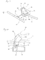
  • FIG. 7 is a schematic, perspective view showing a wire harness-side portion of the lever-type connector of the invention.
  • Fig. 8 is a view similar to Fig. 5, but showing the lever-type connector of the invention.
  • Fig. 9A is a view similar to Fig. 8, but showing the process of a connecting operation, and
  • Fig. 9B is a view similar to Fig. 8, but showing a connected condition.
  • those elements, similar to those of Figs. 3 to 6, are designated by identical reference numerals, respectively.
  • Figs. 8 and 9 the showing of a clamp and a clamp-mounting hole (described later) is omitted for convenience' sake.
  • a connector portion 12 is mounted on a distal end of a wire harness 11 as in the conventional type.
  • a connector-connecting portion 14 is formed on an electric connection box (not shown), and the connector portion 12 can be received in the interior of this connector-connecting portion.
  • a lever piece 15A is pivotally mounted on the connector portion 12 by pin members 16, and cam members 17 are mounted on the connector portion 12. Cam grooves 18, corresponding respectively to the cam members 17, are formed in the lever piece 15A.
  • the electric connection box is similar in structure to that shown in Figs.
  • channel-shaped grooves 19 and channel-shaped grooves 20 are formed in inner surfaces of the connector-connecting portion 14, and the grooves 19 guide the pin members 16, respectively, and are engaged respectively with the pin members 16 when the connector portion 12 is connected to the connector-connecting portion, and the grooves 20 guide the cam members 17, respectively, and are engaged respectively with the cam members 17 when the connector portion 12 is connected to the connector-connecting portion.
  • the lever-type connector of this embodiment much differs in structure from the conventional type in the following points.
  • the clamp-mounting hole 22 is formed in a rear portion of the lever piece 15A, and wall portions 26, which form a receiving portion 25 for receiving a wire harness 24 having the clamp 23 secured thereto, extend from the rear portion 21.
  • the clamp-mounting hole 22 serves to retain and fix the clamp 23 secured to the wire harness 24.
  • the clamp 23 is fixedly secured to the wire harness 24 by known fixing means such as a winding tape or a fastening band.
  • the clamp 23, secured to the wire harness 24, is inserted into the mounting hole 22, formed in the lever piece 15A, and is retained and fixed relative thereto.
  • the wire harness 24 is fixedly secured to the lever piece 15A.
  • that portion of the wire harness 24, to which the clamp 23 is secured is received in the receiving portion 25, and is prevented by the wall portions 26 from lateral movement.
  • the wire harness 24 is fixedly secured to the lever piece 15A by the retaining engagement of the clamp 23 (mounted on the wire harness 24) in the mounting hole 22 formed in the lever piece 15A, as shown in Fig. 10.
  • the fixing of the wire harness 24 to the lever piece may be effected by withdrawal prevention members 27 formed respectively on the inner surfaces of the wall portions 26, as shown in Fig. 11.
  • the wall portions, forming the receiving portion 25 may be deformed into such a configuration as to fix the wire harness in a gripping manner.
  • any suitable fixing member for fixing the wire harness 24 may be provided at the rear portion of the lever piece.
  • cam members 17 and the cam grooves 18, which jointly form the cam mechanism are provided at the lever piece (15A) side
  • cam members are provided at the lever piece side while the cam grooves are provided at the connector-connecting portion of the electric connection box, or there may be adopted the reverse combination thereof.
  • first and second wire harnesses fixedly secured respectively to the connector portion and the lever piece, may be separate from each other, or may be two wire harnesses branching off from one wire harness.
  • the lever piece and the connector-connecting portion of the electric connection box are not limited to the respective illustrated configurations, but can be changed into desired configurations, respectively.
  • the lever-type connector of the present invention is described in the foregoing, and according to the present invention, there is provided the wire harness-mounting structure, using this lever-type connector.
  • this mounting structure has advantages that the recovery of the wire harnesses can be effected easily and that the mounting of the wire harnesses is easy.
  • the method in which the pulling force of the hook of the lifting machine is caused to act on the second wire harness in the wire harness-mounting structure, and by doing so, the lever piece of the lever-type connector is automatically operated so as to effect the removal of the first wire harness, and also the removal of the second wire harness is effected. Therefore, advantageously, the wire harness-removing operation is easy, and the recovery cost can be reduced, and besides the recovery rate can be increased.
  • the above construction and method are adopted, and therefore the wire harnesses can be smoothly removed and recovered without being cut at their intermediate portion at the time of disassembling a discarded vehicle. Therefore, the efficiency of the wire harness-removing operation is enhanced, and the recovery cost is reduced, and besides the recovery rate is increased.
Landscapes

  • Details Of Connecting Devices For Male And Female Coupling (AREA)
  • Insertion, Bundling And Securing Of Wires For Electric Apparatuses (AREA)
  • Connector Housings Or Holding Contact Members (AREA)

Abstract

A lever-type connector includes a frame-like connector-connecting portion for releasably receiving a connector 12 connected to a first wire harness 11, a lever piece 15A for being pivotally supported relative to the connector-connecting portion, and a cam mechanism 17, 18 for engaging the connector-connecting portion and the lever piece 15A with each other so as to bring the lever piece 15A into a connected condition and a released condition relative to the connector-connecting portion. The lever piece 15A has a mounting mechanism 22 for fixedly mounting a second wire harness 24 thereon. When a pulling force is applied to the second wire harness 24 fixedly mounted on the mounting mechanism of the lever piece 15A, the lever piece 15A is operated. <IMAGE>

Description

BACKGROUND OF THE INVENTION
This invention relates to a lever-type connector used for connecting a connector, mounted on an end portion of a wire harness, to a mating connector, a wire harness-mounting structure and a wire harness-removing method, using this connector, and more particularly the invention relates to these techniques which facilitate the recycling.
As is well known, electric connection boxes, such as a junction box (J/B), a relay box (R/B) and an electronic control unit box (ECU/B), are mounted on an automobile to form circuits for connecting wire harnesses to electrical equipments. Such electric connection box has electric circuits (formed by metallic bus bars), such as a power distribution circuit, contained in a casing thereof, and a plurality of connector-connecting portions each for electrical connection to a connector, mounted on an end portion of the wire harness, are formed on the outside of the casing.
On the other hand, recently, the environmental problem has received wider appreciation, and the effective recycling of the resources has become a large problem to be solved. With respect to such a problem, even discarded automobiles are not an exception. The amount of wire harnesses, used in recent electronically-controlled automobiles, are vast, and the recycling of these wire harnesses can not be ignored in the existing circumstances.
Here, an example of a conventional connector-connecting structure in an electric connection box or the like will be schematically described with reference to Figs. 1 and 2. In these Figures, a connector portion 2 is mounted on a distal end of a wire harness 1. On the other hand, a connector-connecting portion 4 is formed on the electric connection box 3, and the connector portion 2 can be received in the interior 5 of this connector-connecting portion. A retaining claw 6 is provided at the connector portion 2, and the connector-connecting portion 4 has a retaining hole 7 for engagement with the retaining claw 6 to prevent the disengagement of the connector portion 2.
Incidentally, for removing a wire harness from a vehicle body to recover it at the time of disassembling a discarded vehicle, a lifting machine, such as a crane, is used, and in this case a J-shaped hook of the machine is brought into engagement with the wire harness, and is lifted so as to remove the wire harness. This is schematically shown in Fig. 3. In this Figure, reference numeral 8 denotes the J-shaped hook provided at the lifting machine such as a crane, and reference numeral 9 denotes the vehicle body. In the case where the connection between the connector portion 2 of the wire harness 1 and the connector-connecting portion 4 of the electric connection box 3 was very firm, the wire harness 1 was cut off when removing the wire harness, and part of the wire harness failed to be recovered, and therefore the problem with this method was the recovery rate.
There is known another conventional connecting structure using a lever-type connector. An example of such lever-type connector is schematically shown in Figs. 4 to 6. Fig. 4 is a perspective view of the lever-type connector, showing a condition before the connection is effected, Fig. 5 is a partly-broken view as seen from the side, Fig. 6A is a view similar to Fig. 5, but showing the process of the connecting operation, and Fig. 6B is a view similar to Fig. 5, but showing the connected condition.
In these Figures, a connector portion 12 is mounted on a distal end of a wire harness 11. On the other hand, a connector-connecting portion 14 is formed on an electric connection box 13, and the connector portion 12 can be received in the interior 15 of this connector-connecting portion. A lever piece 15 is pivotally mounted on the connector portion 12 by pin members 16, and cam members 17 are mounted on the connector portion 12. Cam grooves 18, corresponding respectively to the cam members 17, are formed in the lever piece 15. On the other hand, channel-shaped grooves 19 and channel-shaped grooves 20 are formed in inner surfaces of the connector-connecting portion 14 of the electric connection box 13, and the grooves 19 guide the pin members 16, respectively, and are engaged respectively with the pin members 16 when the connector portion 12 is connected to the connector-connecting portion, and the grooves 20 guide the cam members 17, respectively, and are engaged respectively with the cam members 17 when the connector portion 12 is connected to the connector-connecting portion.
In the above construction, the connector portion 12, connected to the distal end of the wire harness 11, is inserted into the connector-connecting portion 14, with the lever piece 15 held in a released condition (in an upper position) , as shown in Fig. 5. At the time of insertion of the connector portion 12, the pin members 16 are fitted respectively into the grooves 19 in such a manner that the cam members 17 move along the grooves 20, respectively. When the connector portion 12 is inserted to a certain degree, each pin member 16 reaches a lowermost portion of the corresponding groove 19 (Fig. 6A), and thereafter the lever piece 15 is pivotally moved right about the pin members 16 each held in this lowermost portion, and therefore each cam member 17 moves in accordance with the configuration of the cam groove 18. Finally, the lever piece 15 is brought into a recumbent condition as shown in Fig. 6B, and the connected condition is achieved, thus completing the connection of the connector portion 12 to the connector-connecting portion 14.
In the above construction, for disconnecting the connector portion 12 from the connector-connecting portion 14, the operator pulls the lever piece 15 up with the hand, so that the connection is canceled, and therefore the connector portion can be disconnected.
Even in the above conventional lever-type connector, however, when a pulling force is applied to the wire harness in order to remove the wire harness from a discarded vehicle to recover it, without canceling the retained condition by pulling the lever piece 15 up with the hand, the wire harness 11 is cut off, and fails to be recovered. And besides, the retained condition is canceled by pulling the lever piece 15 up by the hand of the operator, and therefore in the case where there are provided many lever-type connectors, much time and labor are required for the recovery, and therefore there is encountered problems that the efficiency of the operation is low and that the cost increases.
SUMMARY OF THE INVENTION
This invention is made in order to overcome the difficulties of the above conventional techniques, and an object of the invention is to provide a lever-type connector in which a wire harness can be easily removed and recovered efficiently with a simple structure without the use of any special member or the like at the time of disassembling a discarded vehicle, and also to provide a wire harness-mounting structure and a wire harness-removing method, using this connector.
In the present invention, the above problems is solved by adopting the following technical means.
  • (1) A lever-type connector comprising:
  • a frame-like connector-connecting portion for releasably receiving a connector connected to a first wire harness;
  • a lever piece for being pivotally supported relative to the connector-connecting portion; and
  • a cam mechanism for engaging the connector-connecting portion and the lever piece with each other so as to bring the lever piece into a connected condition and a released condition relative to the connector-connecting portion, wherein
  • the lever piece has a mounting mechanism for fixedly mounting a second wire harness thereon; and
  • when a pulling force is applied to the second wire harness fixedly mounted on the mounting mechanism of the lever piece, the lever piece is operated.
  • (2) A lever-type connector according to the above Item (1), in which the second wire harness has a clamp secured thereto, and the mounting mechanism of the lever piece is a mounting hole in which the clamp is mounted.
  • (3) A lever-type connector according to the above Item (1), in which the mounting mechanism of the lever piece is a withdrawal prevention member for preventing the withdrawal of the second wire harness after the second wire harness is mounted on the lever piece.
  • (4) A wire harness-mounting structure, wherein the wire harnesses are fixedly mounted by using a lever-type connector as defined in any one of the above Items (1) to (3).
  • (5) A wire harness-removing method for a wire harness-mounting structure as defined in the above Item (4), comprising the steps of applying a pulling force from a lifting machine to the second wire harness to operate the lever piece of the lever-type connector, removing the first wire harness, and removing the second wire harness.
  • BRIEF DESCRIPTION OF THE DRAWINGS
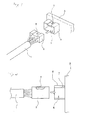
  • Fig. 1 is a perspective view showing an example of a conventional connector-connecting structure.
  • Fig. 2 is a partly-cross-sectional view of the connector-connecting structure of Fig. 1.
  • Fig. 3 is a view showing the manner of removing a wire harness in the connector-connecting structure of Figs. 1 and 2.
  • Fig. 4 is a perspective view showing the structure of a conventional lever-type connector, showing a condition before the connection is effected.
  • Fig. 5 is a partly-broken side-elevational view of the conventional lever-type connector, showing the condition before the connection is effected.
  • Figs. 6A and 6B are partly-broken views of the conventional lever-type connector, and Fig. 6A shows the process of the connecting operation, and Fig. 6B shows the connected condition.
  • Fig. 7 is a perspective view showing the structure of a wire harness-side connector portion of a lever-type connector embodying the invention.
  • Fig. 8 is a partly-broken side-elevational view of the lever-type connector of the invention, showing a condition before the connection is effected.
  • Figs. 9A and 9B are partly-broken views of the lever-type connector of the invention, and Fig. 9A shows the process of the connecting operation, and Fig. 9B shows the connected condition.
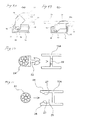
  • Fig. 10 is a view showing one method of fixedly mounting a wire harness on a lever piece.
  • Fig. 11 is a view showing another method of fixedly mounting the wire harness on the lever piece.
  • DETAILED DESCRIPTION OF THE PREFERRED EMBODIMENTS
    A preferred embodiment of the present invention will now be described.
    A preferred embodiment of a lever-type connector of the invention is schematically shown in Figs. 7 to 9. Fig. 7 is a schematic, perspective view showing a wire harness-side portion of the lever-type connector of the invention. Fig. 8 is a view similar to Fig. 5, but showing the lever-type connector of the invention. Fig. 9A is a view similar to Fig. 8, but showing the process of a connecting operation, and Fig. 9B is a view similar to Fig. 8, but showing a connected condition. In these Figures, those elements, similar to those of Figs. 3 to 6, are designated by identical reference numerals, respectively. In Figs. 8 and 9, the showing of a clamp and a clamp-mounting hole (described later) is omitted for convenience' sake.
    In the lever-type connector of this embodiment, a connector portion 12 is mounted on a distal end of a wire harness 11 as in the conventional type. On the other hand, a connector-connecting portion 14 is formed on an electric connection box (not shown), and the connector portion 12 can be received in the interior of this connector-connecting portion. A lever piece 15A is pivotally mounted on the connector portion 12 by pin members 16, and cam members 17 are mounted on the connector portion 12. Cam grooves 18, corresponding respectively to the cam members 17, are formed in the lever piece 15A. On the other hand, the electric connection box is similar in structure to that shown in Figs. 3 to 6, and channel-shaped grooves 19 and channel-shaped grooves 20 are formed in inner surfaces of the connector-connecting portion 14, and the grooves 19 guide the pin members 16, respectively, and are engaged respectively with the pin members 16 when the connector portion 12 is connected to the connector-connecting portion, and the grooves 20 guide the cam members 17, respectively, and are engaged respectively with the cam members 17 when the connector portion 12 is connected to the connector-connecting portion.
    Although the above structure is similar to that of the conventional type of Figs. 4 to 6 except the lever piece 15A, the lever-type connector of this embodiment much differs in structure from the conventional type in the following points. Namely, the clamp-mounting hole 22 is formed in a rear portion of the lever piece 15A, and wall portions 26, which form a receiving portion 25 for receiving a wire harness 24 having the clamp 23 secured thereto, extend from the rear portion 21. The clamp-mounting hole 22 serves to retain and fix the clamp 23 secured to the wire harness 24. The clamp 23 is fixedly secured to the wire harness 24 by known fixing means such as a winding tape or a fastening band.
    In the above construction, the clamp 23, secured to the wire harness 24, is inserted into the mounting hole 22, formed in the lever piece 15A, and is retained and fixed relative thereto. As a result, the wire harness 24 is fixedly secured to the lever piece 15A. In this condition, that portion of the wire harness 24, to which the clamp 23 is secured, is received in the receiving portion 25, and is prevented by the wall portions 26 from lateral movement.
    The subsequent connecting operation is similar to that shown in Figs. 3 to 6, and the connector portion 12, connected to the distal end of the wire harness 11, is inserted into the connector-connecting portion 14, with the lever piece 15A held in a released condition (in an upper position), as shown in Fig. 8. At the time of insertion of the connector portion 12, the pin members 16 are fitted respectively into the grooves 19 in such a manner that the cam members 17 move along the grooves 20, respectively. When the connector portion 12 is inserted to a certain degree, each pin member 16 reaches a lowermost portion of the corresponding groove 19 (Fig. 9A), and thereafter the lever piece 15A is pivotally moved right about the pin members 16 each held in this lowermost portion, and therefore each cam member 17 moves in accordance with the configuration of the cam groove 18. Finally, the lever piece 15A is brought into a recumbent condition as shown in Fig. 9B, and the connected condition is achieved, thus completing the connection of the connector portion 12 to the connector-connecting portion 14.
    In the above construction, for disconnecting the connector portion 12 from the connector-connecting portion 14, a pulling force is applied to the wire harnesses 11 and 24 through a J-shaped hook (not shown) of a lifting machine such as a crane, thereby pulling the wire harnesses up. At this time, when the pulling force is applied in a direction of arrow P (Fig. 7) , this pulling force is transmitted to the lever piece 15A through the wire harness 24, so that the lever piece 15A is operated or moved from its recumbent condition into its lifted condition. As a result, the connected condition of the lever-type connector is automatically canceled. By further applying the pulling force, not only the wire harness 11 but also the wire harness 24 can be removed and recovered without being cut off at their intermediate portion. And besides, the connection and disconnection of the connector can be easily effected with the simple structure without the use of any special part or the like, and the wire harnesses can be efficiently removed and recovered.
    Although one preferred embodiment of the present invention is described above in detail, the invention is not limited to the above embodiment, but various modifications and changes can be made.
    For example, in the above embodiment, the wire harness 24 is fixedly secured to the lever piece 15A by the retaining engagement of the clamp 23 (mounted on the wire harness 24) in the mounting hole 22 formed in the lever piece 15A, as shown in Fig. 10. However, the fixing of the wire harness 24 to the lever piece may be effected by withdrawal prevention members 27 formed respectively on the inner surfaces of the wall portions 26, as shown in Fig. 11. In another modification, the wall portions, forming the receiving portion 25, may be deformed into such a configuration as to fix the wire harness in a gripping manner. In a further modification, any suitable fixing member for fixing the wire harness 24 may be provided at the rear portion of the lever piece.
    In the above embodiment, although the cam members 17 and the cam grooves 18, which jointly form the cam mechanism, are provided at the lever piece (15A) side, there may be adopted a construction in which the cam members are provided at the lever piece side while the cam grooves are provided at the connector-connecting portion of the electric connection box, or there may be adopted the reverse combination thereof.
    In the present invention, the first and second wire harnesses, fixedly secured respectively to the connector portion and the lever piece, may be separate from each other, or may be two wire harnesses branching off from one wire harness.
    The lever piece and the connector-connecting portion of the electric connection box are not limited to the respective illustrated configurations, but can be changed into desired configurations, respectively.
    The lever-type connector of the present invention is described in the foregoing, and according to the present invention, there is provided the wire harness-mounting structure, using this lever-type connector. For the reasons described above, this mounting structure has advantages that the recovery of the wire harnesses can be effected easily and that the mounting of the wire harnesses is easy.
    Further, according to the present invention, there is provided the method in which the pulling force of the hook of the lifting machine is caused to act on the second wire harness in the wire harness-mounting structure, and by doing so, the lever piece of the lever-type connector is automatically operated so as to effect the removal of the first wire harness, and also the removal of the second wire harness is effected. Therefore, advantageously, the wire harness-removing operation is easy, and the recovery cost can be reduced, and besides the recovery rate can be increased.
    As described above in detail, in the present invention, the above construction and method are adopted, and therefore the wire harnesses can be smoothly removed and recovered without being cut at their intermediate portion at the time of disassembling a discarded vehicle. Therefore, the efficiency of the wire harness-removing operation is enhanced, and the recovery cost is reduced, and besides the recovery rate is increased.

    Claims (5)

    1. A lever-type connector comprising:
      a frame-like connector-connecting portion for releasably receiving a connector connected to a first wire harness;
      a lever piece for being pivotally supported relative to said connector-connecting portion; and
      a cam mechanism for engaging said connector-connecting portion and said lever piece with each other so as to bring said lever piece into a connected condition and a released condition relative to said connector-connecting portion, wherein
      said lever piece has a mounting mechanism for fixedly mounting a second wire harness thereon; and
      when a pulling force is applied to said second wire harness fixedly mounted on said mounting mechanism of said lever piece, said lever piece is operated.
    2. The lever-type connector according to claim 1, wherein
         said second wire harness has a clamp secured thereto, and
         said mounting mechanism of said lever piece is a mounting hole in which said clamp is mounted.
    3. The lever-type connector according to claim 1, wherein
         said mounting mechanism of said lever piece is a withdrawal prevention member for preventing the withdrawal of said second wire harness after said second wire harness is mounted on said lever piece.
    4. The wire harness-mounting structure, wherein
         said wire harnesses are fixedly mounted by using a lever-type connector as defined in any one of claims 1 to 3.
    5. A wire harness-removing method for a wire harness-mounting structure as defined in claim 4, comprising the steps of:
      applying a pulling force from a lifting machine to said second wire harness to operate said lever piece of said lever-type connector,
      removing said first wire harness, and
      removing the second wire harness.
    EP02018712A 2001-08-22 2002-08-21 Lever-type connector, wire harness-mounting structure and wire harness-removing method using the same Withdrawn EP1286426A1 (en)

    Applications Claiming Priority (2)

    Application Number Priority Date Filing Date Title
    JP2001252019A JP2003059582A (en) 2001-08-22 2001-08-22 Lever type connector, mounting structure of wire harness using the same, and method of removing wire harness
    JP2001252019 2001-08-22

    Publications (1)

    Publication Number Publication Date
    EP1286426A1 true EP1286426A1 (en) 2003-02-26

    Family

    ID=19080565

    Family Applications (1)

    Application Number Title Priority Date Filing Date
    EP02018712A Withdrawn EP1286426A1 (en) 2001-08-22 2002-08-21 Lever-type connector, wire harness-mounting structure and wire harness-removing method using the same

    Country Status (2)

    Country Link
    EP (1) EP1286426A1 (en)
    JP (1) JP2003059582A (en)

    Cited By (2)

    * Cited by examiner, † Cited by third party
    Publication number Priority date Publication date Assignee Title
    DE102004034188B4 (en) * 2003-07-15 2007-09-06 Sumitomo Wiring Systems, Ltd., Yokkaichi Electrical connector box
    CN114334264A (en) * 2021-12-29 2022-04-12 优网云计算有限公司 File information data transmission device based on photoelectric information

    Citations (3)

    * Cited by examiner, † Cited by third party
    Publication number Priority date Publication date Assignee Title
    FR2659502A1 (en) * 1990-03-06 1991-09-13 Bernier Ets Quick-disconnect connection device
    DE4214016A1 (en) * 1992-04-29 1993-11-04 Volker Breust Protective contact plug with L=section lever pivoted between segments - requires upward pressure for extraction from wall-mounted socket by leverage about shorter end of cable guide in plane of sepn.
    US5330411A (en) * 1991-10-21 1994-07-19 Sumitomo Wiring Systems, Ltd. Lever-type connector

    Patent Citations (3)

    * Cited by examiner, † Cited by third party
    Publication number Priority date Publication date Assignee Title
    FR2659502A1 (en) * 1990-03-06 1991-09-13 Bernier Ets Quick-disconnect connection device
    US5330411A (en) * 1991-10-21 1994-07-19 Sumitomo Wiring Systems, Ltd. Lever-type connector
    DE4214016A1 (en) * 1992-04-29 1993-11-04 Volker Breust Protective contact plug with L=section lever pivoted between segments - requires upward pressure for extraction from wall-mounted socket by leverage about shorter end of cable guide in plane of sepn.

    Cited By (4)

    * Cited by examiner, † Cited by third party
    Publication number Priority date Publication date Assignee Title
    DE102004034188B4 (en) * 2003-07-15 2007-09-06 Sumitomo Wiring Systems, Ltd., Yokkaichi Electrical connector box
    DE102004034188B8 (en) * 2003-07-15 2008-01-03 Sumitomo Wiring Systems, Ltd., Yokkaichi Electrical connector box
    CN114334264A (en) * 2021-12-29 2022-04-12 优网云计算有限公司 File information data transmission device based on photoelectric information
    CN114334264B (en) * 2021-12-29 2022-11-25 优网云计算有限公司 File information data transmission device based on photoelectric information

    Also Published As

    Publication number Publication date
    JP2003059582A (en) 2003-02-28

    Similar Documents

    Publication Publication Date Title
    US5487678A (en) Connector housing having a lock mechanism
    EP1548892A1 (en) Electrical connector
    EP3133702B1 (en) Connector system with disconnection evident connector position assurance feature
    US5599200A (en) Connector with a terminal protecting board
    EP1286426A1 (en) Lever-type connector, wire harness-mounting structure and wire harness-removing method using the same
    JP2835675B2 (en) Locking device for electronic unit
    CN110386103B (en) Anti-theft device for vehicle gear lever
    JPH11126664A (en) Electric connector, and method and tool for releasing electric contact from insulating housing
    JP2001307823A (en) Mounting structure for automotive electrical components
    KR200452236Y1 (en) Emergency release of auto connector
    US20020187673A1 (en) Connector and a method for disengaging it
    JP3117125B2 (en) Automatic mating mechanism between connectors
    EP3076492B1 (en) Electrical connector system with laterally protruding releasing arm
    US5634824A (en) Method of and construction for fitting optional connector relative to high-density multi-pole connector
    JP2002171637A (en) Mounting structure for electrical junction box
    JPH10233131A (en) Grommet mounting jig
    CN222637802U (en) Connector
    JP5000561B2 (en) Electrical connection device for vehicle
    US20200303887A1 (en) Electronic coupler removal tool
    JP3817882B2 (en) Grommet threading method for wire harness
    JP5082244B2 (en) Electrical component
    JP2025110462A (en) Electrical component puller fixing structure and electrical connection box
    KR102829333B1 (en) Connector structure of power converter apparatus for vehicle
    JP2011229302A (en) Case
    KR100737577B1 (en) Wiring Harness Fixing Clip

    Legal Events

    Date Code Title Description
    PUAI Public reference made under article 153(3) epc to a published international application that has entered the european phase

    Free format text: ORIGINAL CODE: 0009012

    AK Designated contracting states

    Kind code of ref document: A1

    Designated state(s): AT BE BG CH CY CZ DE DK EE ES FI FR GB GR IE IT LI LU MC NL PT SE SK TR

    Designated state(s): AT BE BG CH CY CZ DE DK EE ES FI FR GB GR IE IT LI LU MC NL PT SE SK TR

    AX Request for extension of the european patent

    Extension state: AL LT LV MK RO SI

    17P Request for examination filed

    Effective date: 20030627

    AKX Designation fees paid

    Designated state(s): DE FR GB

    STAA Information on the status of an ep patent application or granted ep patent

    Free format text: STATUS: THE APPLICATION IS DEEMED TO BE WITHDRAWN

    18D Application deemed to be withdrawn

    Effective date: 20050301