EP1286370A2 - Corrosion resistant pencil coil having external secondary winding and shield - Google Patents
Corrosion resistant pencil coil having external secondary winding and shield Download PDFInfo
- Publication number
- EP1286370A2 EP1286370A2 EP02078042A EP02078042A EP1286370A2 EP 1286370 A2 EP1286370 A2 EP 1286370A2 EP 02078042 A EP02078042 A EP 02078042A EP 02078042 A EP02078042 A EP 02078042A EP 1286370 A2 EP1286370 A2 EP 1286370A2
- Authority
- EP
- European Patent Office
- Prior art keywords
- recited
- protective coating
- case
- shield
- approximately
- Prior art date
- Legal status (The legal status is an assumption and is not a legal conclusion. Google has not performed a legal analysis and makes no representation as to the accuracy of the status listed.)
- Granted
Links
Images




Classifications
-
- H—ELECTRICITY
- H01—ELECTRIC ELEMENTS
- H01F—MAGNETS; INDUCTANCES; TRANSFORMERS; SELECTION OF MATERIALS FOR THEIR MAGNETIC PROPERTIES
- H01F38/00—Adaptations of transformers or inductances for specific applications or functions
- H01F38/12—Ignition, e.g. for IC engines
Definitions
- This invention pertains generally to the construction of pencil ignition coils used in the automotive industry, and more particularly to methods of preventing case erosion in pencil coils having a secondary wound external to the primary and the shields located external to the case.
- Automotive pencil ignition coils known in the art are generally used to transform voltage from the 12-volt battery to a substantially higher voltage needed for ignition. Such ignition coils typically have a core with primary and secondary windings.
- a pencil ignition coil that has a secondary winding external to its primary winding and a shield located external to a case will yield a higher energy capability than one where the primary is wound external to the secondary. The higher energy capability is obtained because the primary winding may be wound onto a core, which eliminates the need for a spool and allows for a larger core and greater energy density.
- FIG. 1 is a schematic diagram showing the basic configuration of an ignition coil 10, having a primary winding 12 around core 14 which is internal to a secondary winding 16. These elements are housed in a case 18 covered by a shield 20, wherein an air gap 22 is located between the case 18 and the shield 20. The air gap 22 is not drawn to scale.
- a pencil ignition coil having a configuration as shown in FIG. 1 may suffer damage to the case 18 because of the high electrical field that occurs between the case and the shield.
- partial discharge arises from ionization of air 24 in the gap 22 located between the case 18 and the shield 20, producing ozone (O 3 ) 26.
- This ionization of air 24 into ozone 26 is called the phenomenon of "partial discharge” and occurs whenever an air gap 22 wider than approximately five microns experiences the presence of a high electric field as is typically created by a pencil ignition coil 10 having an internal primary winding 12, an external secondary winding 16, and a shield 20 located external to the case 18.
- Partial discharge causes case-erosion, resulting in an eroded layer 28, which leads to eventual failure of the entire pencil ignition coil 10. Therefore, there is a need for a method of inhibiting case erosion in pencil ignition coils that has an internal primary winding.
- the present invention satisfies that need, as well as others, and overcomes the deficiencies found in conventional coils.
- the present invention comprises a protected erosion-resistant pencil ignition coil assembly and a method for fabricating the erosion-resistant pencil ignition coil assembly.
- the present invention also comprises several means for resisting damage due to the partial discharge phenomenon: (1) fabricating a pencil ignition coil having a coating for resisting erosion of the case by ozone; (2) fabricating a pencil ignition coil having a coating for eliminating partial discharge under a shield; and (3) fabricating a pencil coil having a polyimide tape covering for resisting partial discharge under a shield.
- a polyimide tube may also be used, assembled over the case and under the shield.
- the case is coated with a material that is resistant to the ozone that is produced when the air ionizes upon partial discharge.
- Suitable materials include, but are not limited to, titanium dioxide or silicon dioxide in a base such as paint, E-coat, polyester, or any other material that acts as a carrier and adheres to the case when dried or cured.
- the case is either electroplated or coated with a substrate material such as paint, polyester, epoxy or the like that is highly filled with a conductive material.
- a substrate material such as paint, polyester, epoxy or the like that is highly filled with a conductive material.
- Suitable conductive materials include, but are not limited to, carbon black, aluminum, or iron.
- This coating would be in electrical contact with the shield that is also grounded and in intimate contact with the case. With the coating and the shield at the same potential, no field would exist between them and, therefore, the air could not ionize to produce ozone. This would also reduce electrical noise since the partial discharges are eliminated.
- one or more layers of Kapton CRTM tape, or other corona resistant polyimide are attached to the case between the case and the shield.
- Kapton CRTM tape or other corona resistant polyimide
- a one half millimeter to three millimeter thick base polyimide material with a one half millimeter to two millimeter thick glue coating would be suitable.
- the tape would be pressed onto the case so that the glue displaces the air between the tape and case.
- the air between the tape and the shield may still ionize, but the tape would resist damage to the case from the partial discharge that would result from the ionization.
- An object of the invention is to inhibit ozone caused case erosion in pencil coils having an internal primary winding.
- Another object of the invention is to inhibit case damage from partial discharge in pencil coils having an internal primary winding.
- Another object of the invention is to eliminate partial discharge in pencil coils having an internal primary winding. Another object of the invention is to provide for increased commercial value by allowing the use of an efficient internal primary winding that increases energy density.
- Another object of the invention to eliminate the need for a spool in pencil coils, thereby lowering the manufacturing costs.
- Another object of the invention is to provide for ease of processing by coating or molding.
- Another object of the invention is to reduce electrical noise.
- Another object of the invention is to improve durability even through thermal cycling.
- Another object of the invention is to lower case manufacturing costs by allowing the use of lower cost plastics.
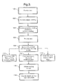
- FIG. 3 through FIG. 6 the apparatus and methods generally shown in FIG. 3 through FIG. 6. It will be appreciated that the apparatus may vary as to configuration and as to details of the parts, and that the method may vary as to the specific steps and sequence, without departing from the basic concepts as disclosed herein.
- the method comprises the steps of providing a core as indicated by block 100; winding a primary around the core as indicated in block 102; providing a secondary winding, wherein said primary winding is internal to said secondary winding as indicated by block 104; providing a case as indicated by block 106; housing the core wound with the primary winding internal to the secondary winding in the case as indicated by block 108; coating the surface of the case with a protective material such as a TiO 2 or SiO 2 loaded polymer as indicted in block 110, a C, Al or Fe loaded polymer as indicated in block 112, or Kapton CRTM tape as indicated in block 114, thereby forming a coating film; causing said coating film to adhere to the surface of the case, thereby forming said protective coating on said surface of said case as indicated by block 116; and providing at least one shield for enclosing the case, wherein said shield is external to said
- FIG. 4 illustrates a pencil ignition coil assembly 200 fabricated according to the above-described method.
- Coil 200 has an erosion-resistant coating 202 located on a surface 18a of a case 18 that is between the case 18 and shield 20 for resisting erosion of the case 18 by ozone (O 3 ) 26 generated by ionizing air 24 in air gap 22 as fabricated according to the method of the present invention wherein the coating step shown in block 110 is employed.
- O 3 ozone
- the erosion-resistant coating 202 preferably comprises a base material 204 with good adhesive properties such as a paint, an epoxy, a polyester, a polyurethane, or any other suitable curable carrier material and an ozone-resistant inorganic additive 206 such as titanium dioxide, titania (TiO 2 ), or silicon dioxide, silica (SiO 2 ).
- a base material 204 with good adhesive properties such as a paint, an epoxy, a polyester, a polyurethane, or any other suitable curable carrier material and an ozone-resistant inorganic additive 206 such as titanium dioxide, titania (TiO 2 ), or silicon dioxide, silica (SiO 2 ).
- FIG. 5 shows a pencil ignition coil assembly 300 fabricated according to the above-described method wherein the coating step shown in block 112 is employed.
- Coil 300 has a conductive coating 302 located on a surface 18a of a case 18 between the case 18 and shield 20.
- the conductive coating 302 is in electrical contact 304 with the shield 20, and, therefore, would have the same potential as the shield 20.
- the shield 20 is grounded and in intimate contact with the case 18.
- the air 24 does not ionize in air gap 22 and partial discharge is eliminated. Electrical noise is also eliminated as partial discharges are eliminated.
- the conductive coating 302 preferably comprises a base material 306 with good adhesive properties such as a paint, an epoxy, a polyester, a polyurethane, or any other suitable curable carrier material having a conductive additive 308 such as carbon black (C), aluminum (Al), or iron (Fe).
- a base material 306 with good adhesive properties such as a paint, an epoxy, a polyester, a polyurethane, or any other suitable curable carrier material having a conductive additive 308 such as carbon black (C), aluminum (Al), or iron (Fe).
- the case could be electroplated and the shield placed in intimate contact with the electroplated surface of the case or the electroplating could act as the shield.
- Coil 400 has a corona-resistant polyimide covering 402 such as one or more windings of Kapton CRTM tape or the like located on the surface of the case 18 between case 18 and shield 20 for resisting partial discharge under shield 20.
- the corona-resistant polyimide covering 402 preferably comprises a polyimide film 404 in the range of approximately 0.5 mils to 3.0 mils in thickness and an adhesive layer 406 in the range of approximately 0.5 mils to 2.0 mils in thickness.
- conductive material is also placed in the adhesive layer.
- the corona-resistant polyimide film 404 is pressed onto the surface 18a of the case 18 between the adhesive layer 406 and the shield 20 until all air bubbles are displaced.
- the air 24 outside of the corona-resistant polyimide covering 402 may still ionize, but the corona-resistant polyimide covering 402 resists damage due to partial discharge and the accumulation of ozone.
Landscapes
- Engineering & Computer Science (AREA)
- Power Engineering (AREA)
- Ignition Installations For Internal Combustion Engines (AREA)
- Application Of Or Painting With Fluid Materials (AREA)
Abstract
Description
FIG. 1 may suffer damage to the
Claims (39)
- A method for preventing case erosion in a pencil ignition coil (10) of the type having an internal primary winding (12), an external secondary winding (16), a case (18) surrounding the secondary winding (16), and a shield (20) surrounding the case (18), comprising applying a protective coating (202, 302, 402) to said case (18) between said case (18) and said shield (20).
- A method as recited in claim 1, further comprising curing said protective coating (202, 302, 402) after applying said protective coating (202, 302, 402) to said case (18).
- A method as recited in claim 1, further comprising applying one or more additional protective coating (202, 302, 402) layers to said case (18).
- A method as recited in claim 1, wherein said protective coating (202, 302, 402) comprises a polyimide film.
- A method as recited in claim 3, wherein said additional protective coating (202, 302, 402) layers comprises a polyimide film.
- A method as recited in claim 4, wherein said polyimide film of said protective coating (202, 302, 402) has a thickness in the range of approximately 0.5 mil to approximately 3.0 mils, and wherein said polyimide film has an adhesive backing having a thickness in the range of approximately 0.5 mil to approximately 2.0 mils.
- A method as recited in claim 5, wherein said polyimide film of each of said protective coating (202, 302, 402) layers has a thickness in the range of approximately 0.5 mil to approximately 3.0 mils, and wherein said polyimide film has an adhesive backing having a thickness in the range of approximately 0.5 mil to approximately 2.0 mils.
- A method as recited in claim 1, wherein said protective coating (202, 302, 402) comprises a base material and an additive material.
- A method as recited in claim 3, wherein each of said additional protective coating (202, 302, 402) layers comprises a base material and an additive material.
- A method as recited in claim 8, wherein said base material of said protective coating (202, 302, 402) is selected from the group of polymeric materials consisting essentially of paint, epoxy, polyester, and polyurethane.
- A method as recited in claim 9, wherein said base material of each of said protective coating (202, 302, 402) layers is selected from the group of polymeric materials consisting essentially of paint, epoxy, polyester, and polyurethane.
- A method as recited in claim 8, wherein said additive material of said protective coating (202, 302, 402) is selected from the group of inorganic compounds consisting essentially of titanium dioxide and silicon dioxide.
- A method as recited in claim 9, wherein said additive material of each of said additional protective coating (202, 302, 402) layers is selected from the group of inorganic compounds consisting essentially of titanium dioxide and silicon dioxide.
- A method as recited in claim 8, wherein said additive material of said protective coating (202, 302, 402) is a conductive material.
- A method as recited in claim 14, further comprising the step of conductively bonding said coating (202, 302, 402) to said shield (20).
- A method as recited in claim 14, wherein said conductive material is selected from the group consisting essentially of carbon black, aluminum, and iron.
- A method as recited in claim 9, wherein said additive material of said protective coating (202, 302, 402) is a conductive material.
- A method as recited in claim 17, further comprising the step of conductively bonding said coating (202, 302, 402) to said shield (20).
- A method as recited in claim 17, wherein said conductive material is selected from the group consisting essentially of carbon black, aluminum, and iron.
- A method for preventing case erosion in a pencil ignition coil (10) of the type having an internal primary winding (12), an external secondary winding (16), a case (18) surrounding the secondary winding (16), a shield (20) surrounding the case (18), and an air gap (22) between said shield (20) and said case (18), comprising applying at least one protective coating (202, 302, 402) to said case (18) between said case (18) and said shield (20), wherein said protective coating (202, 302, 402) comprises a base material and an additive material.
- A method as recited in claim 20, wherein said base material of said protective coating (202, 302, 402) comprises a polyimide film and said additive material comprises an adhesive material.
- A method as recited in claim 21, wherein said polyimide film base material has a thickness in the range of approximately 0.5 mil to approximately 3.0 mils, and wherein said polyimide film has an adhesive backing having a thickness in the range of approximately 0.5 mil to approximately 2.0 mils.
- A method as recited in claim 20, wherein said base material of each of said protective coatings (202, 302, 402) is selected from the group of polymeric materials consisting essentially of paint, epoxy, polyester, and polyurethane.
- A method as recited in claim 20, wherein said additive material of each of said protective coatings (202, 302, 402) is selected from the group of inorganic compounds consisting essentially of titanium dioxide and silicon dioxide.
- A method as recited in claim 20, wherein said additive material of each of said protective coatings (202, 302, 402) is selected from the group of conductive materials consisting essentially of carbon black, aluminum, and iron.
- A pencil ignition coil (10) of the type having an internal primary winding (12), an external secondary winding (16), a case (18) surrounding the secondary winding (16), and a shield (20) surrounding the case (18), wherein a protective coating (202, 302, 402) is applied to said case (18) between said case (18) and said shield (20).
- A pencil ignition coil as recited in claim 26, wherein said protective coating (202, 302, 402) comprises a polyimide film.
- A pencil ignition coil as recited in claim 27, wherein said polyimide film has a thickness in the range of approximately 0.5 mil to approximately 3.0 mils, and wherein said polyimide film (404) has an adhesive backing (406) having a thickness in the range of approximately 0.5 mil to approximately 2.0 mils.
- A pencil ignition coil as recited in claim 26, wherein said protective coating (202, 302, 402) comprises a base material and an additive material.
- A pencil ignition coil as recited in claim 29, wherein said base material of said protective coating (202, 302, 402) is selected from the group of polymeric materials consisting essentially of paint, epoxy, polyester, and polyurethane.
- A pencil ignition coil as recited in claim 29, wherein said additive material of said protective coating (202, 302, 402) is selected from the group of inorganic compounds consisting essentially of titanium dioxide and silicon dioxide.
- A pencil ignition coil as recited in claim 29, wherein said additive material of said protective coating (202, 302, 402) is selected from the group consisting essentially of carbon black, aluminum, and iron, and wherein said protective coating is conductively bonded to said shield (20).
- A pencil ignition coil as recited in claim 26, wherein said protective coating (202, 302, 402) further comprises one or more additional protective coating layers.
- A pencil ignition coil as recited in claim 33, wherein said additional protective coating (202, 302, 402) layers comprises a polyimide film.
- A pencil ignition coil as recited in claim 34, wherein said polyimide film has a thickness in the range of approximately 0.5 mil to approximately 3.0 mils, and wherein said polyimide film (404) has an adhesive backing (406) having a thickness in the range of approximately 0.5 mil to approximately 2.0 mils.
- A pencil ignition coil as recited in claim 33, wherein said additional protective coating (202, 302, 402) layers comprise a base material and an additive material.
- A pencil ignition coil as recited in claim 36, wherein said base material of each of said protective coating (202, 302, 402) layers is selected from the group of polymeric materials consisting essentially of paint, epoxy, polyester, and polyurethane.
- A pencil ignition coil as recited in claim 36, wherein said additive material of each of said protective coating (202, 302, 402) layers is selected from the group of inorganic compounds consisting essentially of titanium dioxide and silicon dioxide.
- A pencil ignition coil as recited in claim 36, wherein said additive material of each of said protective coating (202, 302, 402) layers is selected from the group consisting essentially of carbon black, aluminum, and iron, and wherein said protective coating is conductively bonded to said shield (20).
Applications Claiming Priority (2)
| Application Number | Priority Date | Filing Date | Title |
|---|---|---|---|
| US09/933,243 US6556116B2 (en) | 2001-08-20 | 2001-08-20 | Erosion resistant pencil coil having external secondary winding and shield |
| US933243 | 2001-08-20 |
Publications (3)
| Publication Number | Publication Date |
|---|---|
| EP1286370A2 true EP1286370A2 (en) | 2003-02-26 |
| EP1286370A3 EP1286370A3 (en) | 2003-12-03 |
| EP1286370B1 EP1286370B1 (en) | 2010-04-28 |
Family
ID=25463614
Family Applications (1)
| Application Number | Title | Priority Date | Filing Date |
|---|---|---|---|
| EP02078042A Expired - Lifetime EP1286370B1 (en) | 2001-08-20 | 2002-07-25 | Corrosion resistant pencil coil having external secondary winding and shield |
Country Status (3)
| Country | Link |
|---|---|
| US (1) | US6556116B2 (en) |
| EP (1) | EP1286370B1 (en) |
| DE (1) | DE60236126D1 (en) |
Families Citing this family (11)
| Publication number | Priority date | Publication date | Assignee | Title |
|---|---|---|---|---|
| US6644585B2 (en) | 2001-12-10 | 2003-11-11 | Delphi Technologies, Inc. | Solenoid coil assembly and method for winding coils |
| US6758993B2 (en) * | 2002-04-17 | 2004-07-06 | Delphi Technologies, Inc. | System and method for minimizing cure-induced residual stress in an epoxy impregnated ignition coil |
| US6842007B2 (en) * | 2002-10-08 | 2005-01-11 | Delphi Technologies, Inc. | Ignition coil durability testing apparatus and method |
| US6860446B2 (en) * | 2002-11-14 | 2005-03-01 | Delphi Technologies, Inc. | Method and apparatus for winding a coil |
| DE10256802B3 (en) * | 2002-12-05 | 2004-04-15 | Robert Bosch Gmbh | Rod ignition coil for automobile IC engine has first coil body, its coil winding and associated resin mass acting as second coil body for second coil winding |
| US6894597B2 (en) * | 2003-02-21 | 2005-05-17 | Delphi Technologies, Inc. | Axially potted progressive wound remote mount ignition coil |
| US20050046299A1 (en) * | 2003-08-25 | 2005-03-03 | Brown David L. | Windings for electric machines |
| DE502004010487D1 (en) * | 2004-01-27 | 2010-01-21 | Mettler Toledo Ag | Coil with moisture protection layers |
| US7148780B2 (en) | 2005-01-24 | 2006-12-12 | Delphi Technologies, Inc. | Twin spark pencil coil |
| US7332991B2 (en) * | 2005-01-24 | 2008-02-19 | Delphi Technologies, Inc. | Twin spark ignition coil with provisions to balance load capacitance |
| US9737933B2 (en) | 2012-09-28 | 2017-08-22 | General Electric Company | Process of fabricating a shield and process of preparing a component |
Family Cites Families (4)
| Publication number | Priority date | Publication date | Assignee | Title |
|---|---|---|---|---|
| DE19962279C2 (en) * | 1999-01-19 | 2003-04-30 | Bremi Auto Elek K Ernst Bremic | ignition coil |
| JP2000228322A (en) * | 1999-02-08 | 2000-08-15 | Hitachi Ltd | Ignition coil for internal combustion engine |
| US6463674B1 (en) * | 2000-11-27 | 2002-10-15 | Xerox Corporation | Hot air impingement drying system for inkjet images |
| US6463918B1 (en) * | 2001-02-14 | 2002-10-15 | Delphi Technologies, Inc. | Ignition apparatus having an electrically floating shield |
-
2001
- 2001-08-20 US US09/933,243 patent/US6556116B2/en not_active Expired - Fee Related
-
2002
- 2002-07-25 EP EP02078042A patent/EP1286370B1/en not_active Expired - Lifetime
- 2002-07-25 DE DE60236126T patent/DE60236126D1/en not_active Expired - Lifetime
Also Published As
| Publication number | Publication date |
|---|---|
| DE60236126D1 (en) | 2010-06-10 |
| EP1286370A3 (en) | 2003-12-03 |
| EP1286370B1 (en) | 2010-04-28 |
| US6556116B2 (en) | 2003-04-29 |
| US20030034866A1 (en) | 2003-02-20 |
Similar Documents
| Publication | Publication Date | Title |
|---|---|---|
| US6556116B2 (en) | Erosion resistant pencil coil having external secondary winding and shield | |
| US6130495A (en) | Supporting element for an electric winding, turbogenerator and method of producing a corona shield | |
| US6531946B2 (en) | Low noise and low loss reactor | |
| KR101165837B1 (en) | Coil component and fabrication method of the same | |
| US20070272432A1 (en) | Bushing | |
| JP2000228322A (en) | Ignition coil for internal combustion engine | |
| JPS63142622A (en) | Ignition coil for internal combustion engine | |
| US3990029A (en) | Insulated windings provided with a mould releasing material | |
| EP1933332B1 (en) | Insulation system and method for a transformer | |
| CN107039159A (en) | Electric winding, the dry-type transformer with electric winding and the method for manufacturing electric winding | |
| US7045923B2 (en) | Magnetizing method and permanent magnet magnetized thereby | |
| CN111316389B (en) | Electric reactor | |
| KR100883698B1 (en) | Inductor and Inductor Manufacturing Method | |
| JP2022166332A (en) | Coil device | |
| CN112753081B (en) | Conductive tape for electrical insulation, especially for electric motors and transformers | |
| US20030201861A1 (en) | Ignition coil | |
| JPH11317116A (en) | Electromagnetic wave shield material, and electromagnetic wave shield sheet, wire and cable, and cable cover using this | |
| JP2002033213A (en) | Coil and insulating method thereof | |
| CN117355912A (en) | Core structure and coil assembly including same | |
| CN220171907U (en) | Dustproof salt mist prevention reactor | |
| CN111316390B (en) | Electric reactor | |
| JPH0453112A (en) | Stational induction electric machine | |
| JPH11224824A (en) | Ignition coil | |
| JP3954489B2 (en) | Electric wire and electric wire manufacturing method | |
| JPH06176940A (en) | Resin molded coil |
Legal Events
| Date | Code | Title | Description |
|---|---|---|---|
| PUAI | Public reference made under article 153(3) epc to a published international application that has entered the european phase |
Free format text: ORIGINAL CODE: 0009012 |
|
| AK | Designated contracting states |
Designated state(s): AT BE BG CH CY CZ DE DK EE ES FI FR GB GR IE IT LI LU MC NL PT SE SK TR Kind code of ref document: A2 Designated state(s): AT BE BG CH CY CZ DE DK EE ES FI FR GB GR IE IT LI LU MC NL PT SE SK TR |
|
| AX | Request for extension of the european patent |
Extension state: AL LT LV MK RO SI |
|
| PUAL | Search report despatched |
Free format text: ORIGINAL CODE: 0009013 |
|
| RIC1 | Information provided on ipc code assigned before grant |
Ipc: 7F 02P 3/02 B Ipc: 7H 01F 27/36 B Ipc: 7H 01F 38/12 A |
|
| AK | Designated contracting states |
Kind code of ref document: A3 Designated state(s): AT BE BG CH CY CZ DE DK EE ES FI FR GB GR IE IT LI LU MC NL PT SE SK TR |
|
| AX | Request for extension of the european patent |
Extension state: AL LT LV MK RO SI |
|
| 17P | Request for examination filed |
Effective date: 20040603 |
|
| AKX | Designation fees paid |
Designated state(s): DE FR GB |
|
| GRAP | Despatch of communication of intention to grant a patent |
Free format text: ORIGINAL CODE: EPIDOSNIGR1 |
|
| GRAS | Grant fee paid |
Free format text: ORIGINAL CODE: EPIDOSNIGR3 |
|
| GRAA | (expected) grant |
Free format text: ORIGINAL CODE: 0009210 |
|
| AK | Designated contracting states |
Kind code of ref document: B1 Designated state(s): DE FR GB |
|
| REG | Reference to a national code |
Ref country code: GB Ref legal event code: FG4D |
|
| REF | Corresponds to: |
Ref document number: 60236126 Country of ref document: DE Date of ref document: 20100610 Kind code of ref document: P |
|
| PLBE | No opposition filed within time limit |
Free format text: ORIGINAL CODE: 0009261 |
|
| STAA | Information on the status of an ep patent application or granted ep patent |
Free format text: STATUS: NO OPPOSITION FILED WITHIN TIME LIMIT |
|
| 26N | No opposition filed |
Effective date: 20110131 |
|
| PGFP | Annual fee paid to national office [announced via postgrant information from national office to epo] |
Ref country code: FR Payment date: 20110727 Year of fee payment: 10 |
|
| PGFP | Annual fee paid to national office [announced via postgrant information from national office to epo] |
Ref country code: DE Payment date: 20110720 Year of fee payment: 10 Ref country code: GB Payment date: 20110720 Year of fee payment: 10 |
|
| GBPC | Gb: european patent ceased through non-payment of renewal fee |
Effective date: 20120725 |
|
| REG | Reference to a national code |
Ref country code: FR Ref legal event code: ST Effective date: 20130329 |
|
| PG25 | Lapsed in a contracting state [announced via postgrant information from national office to epo] |
Ref country code: GB Free format text: LAPSE BECAUSE OF NON-PAYMENT OF DUE FEES Effective date: 20120725 Ref country code: FR Free format text: LAPSE BECAUSE OF NON-PAYMENT OF DUE FEES Effective date: 20120731 Ref country code: DE Free format text: LAPSE BECAUSE OF NON-PAYMENT OF DUE FEES Effective date: 20130201 |
|
| REG | Reference to a national code |
Ref country code: DE Ref legal event code: R119 Ref document number: 60236126 Country of ref document: DE Effective date: 20130201 |