EP1286172A2 - Magnetic resonance and ultrasound imaging apparatus - Google Patents
Magnetic resonance and ultrasound imaging apparatus Download PDFInfo
- Publication number
- EP1286172A2 EP1286172A2 EP02018005A EP02018005A EP1286172A2 EP 1286172 A2 EP1286172 A2 EP 1286172A2 EP 02018005 A EP02018005 A EP 02018005A EP 02018005 A EP02018005 A EP 02018005A EP 1286172 A2 EP1286172 A2 EP 1286172A2
- Authority
- EP
- European Patent Office
- Prior art keywords
- probe
- tool
- supporting
- diagnostic
- ultrasound
- Prior art date
- Legal status (The legal status is an assumption and is not a legal conclusion. Google has not performed a legal analysis and makes no representation as to the accuracy of the status listed.)
- Granted
Links
Images




Classifications
-
- G—PHYSICS
- G01—MEASURING; TESTING
- G01R—MEASURING ELECTRIC VARIABLES; MEASURING MAGNETIC VARIABLES
- G01R33/00—Arrangements or instruments for measuring magnetic variables
- G01R33/20—Arrangements or instruments for measuring magnetic variables involving magnetic resonance
- G01R33/28—Details of apparatus provided for in groups G01R33/44 - G01R33/64
-
- A—HUMAN NECESSITIES
- A61—MEDICAL OR VETERINARY SCIENCE; HYGIENE
- A61B—DIAGNOSIS; SURGERY; IDENTIFICATION
- A61B5/00—Measuring for diagnostic purposes; Identification of persons
- A61B5/0033—Features or image-related aspects of imaging apparatus, e.g. for MRI, optical tomography or impedance tomography apparatus; Arrangements of imaging apparatus in a room
- A61B5/0035—Features or image-related aspects of imaging apparatus, e.g. for MRI, optical tomography or impedance tomography apparatus; Arrangements of imaging apparatus in a room adapted for acquisition of images from more than one imaging mode, e.g. combining MRI and optical tomography
-
- A—HUMAN NECESSITIES
- A61—MEDICAL OR VETERINARY SCIENCE; HYGIENE
- A61B—DIAGNOSIS; SURGERY; IDENTIFICATION
- A61B5/00—Measuring for diagnostic purposes; Identification of persons
- A61B5/05—Detecting, measuring or recording for diagnosis by means of electric currents or magnetic fields; Measuring using microwaves or radio waves
- A61B5/055—Detecting, measuring or recording for diagnosis by means of electric currents or magnetic fields; Measuring using microwaves or radio waves involving electronic [EMR] or nuclear [NMR] magnetic resonance, e.g. magnetic resonance imaging
-
- A—HUMAN NECESSITIES
- A61—MEDICAL OR VETERINARY SCIENCE; HYGIENE
- A61B—DIAGNOSIS; SURGERY; IDENTIFICATION
- A61B8/00—Diagnosis using ultrasonic, sonic or infrasonic waves
- A61B8/44—Constructional features of the ultrasonic, sonic or infrasonic diagnostic device
- A61B8/4416—Constructional features of the ultrasonic, sonic or infrasonic diagnostic device related to combined acquisition of different diagnostic modalities, e.g. combination of ultrasound and X-ray acquisitions
-
- A—HUMAN NECESSITIES
- A61—MEDICAL OR VETERINARY SCIENCE; HYGIENE
- A61B—DIAGNOSIS; SURGERY; IDENTIFICATION
- A61B5/00—Measuring for diagnostic purposes; Identification of persons
- A61B5/45—For evaluating or diagnosing the musculoskeletal system or teeth
- A61B5/4528—Joints
-
- A—HUMAN NECESSITIES
- A61—MEDICAL OR VETERINARY SCIENCE; HYGIENE
- A61B—DIAGNOSIS; SURGERY; IDENTIFICATION
- A61B8/00—Diagnosis using ultrasonic, sonic or infrasonic waves
Definitions
- the invention relates to a imaging apparatus comprising a magnetic resonance imaging (MRI) apparatus, with at least one transmitting coil for exciting the matter of a body under examination or of a part thereof and at least one coil for receiving the signals transmitted by the body under examination or a part thereof, as well as electronic means for processing said received signals to create an image and which apparatus has further means for supporting an guiding a surgical or therapeutic tool.
- MRI magnetic resonance imaging
- MRI examinations are often combined with the use of various tools, which may consist of diagnostic assistance instruments or of therapeutic instruments.
- This may be the case, for instance, of shoulder dedicated MRI apparatuses, wherein contrast agents are often to be injected in the region under examination.
- the perfusion of said contrast agents shall be as accurate as possible and requires a critical time selection, which may not be easy, especially due to the anatomic peculiarities of the shoulder which, as is known, is a very complex anatomic region, especially when said operations are carried out in a wholly manual manner. In this case, the success of these operations only depends on the skills and expertise of the operator.
- Document EP 1090 594 and US 5,706,812 discloses an MRI apparatus having an RF receiving coil comprising means for supporting a therapeutic tool such as a syringe or a needle.
- the supporting means helps in correctly aiming the tool against the zone to be treated while the imaging apparatus helps in viewing the tool and the part where the tool acts for better controlling the position, the orientation and the effect of the tool.
- this invention has the object of improving the imaging capability of the imaging apparatus for better viewing the part of the body to be treated and the tool which is used, by collecting more or better information thus improving the performances of the imaging apparatus and the precision of positioning and orienting the tool.
- the diagnostic and/or therapeutic instrument whose use is provided in combination with MRI, in relation to the particular anatomy of the region under examination and to the anatomy of the individual patient, and to obtain an optimized synchronization between the various diagnostic and/or therapeutic times, or anyway a better synchronization than is currently possible.
- the invention achieves the above purposes by providing an apparatus as described hereinbefore which includes a ultrasound imaging apparatus having a probe for transmitting and receiving ultrasound pulses as well as electronic means for reconstructing an image from the said pulses and means for supporting and/or guiding the ultrasound probe which are provided in combination with the means for supporting the tool.
- These supporting and/or guiding means for the tool and for the ultrasound probe may be associated to the receiving coil.
- This supporting and/or guiding means for the ultrasound probe and for the tool may be integrated in a unique element or may be separate and independent one form the other.
- the apparatus may include a receiving coil case or enclosure made of a material which does not interfere with Magnetic Resonance signals, generally plastic, whereon the probe and the tool supporting and/or guiding means are supported and/or fastened and/or associated.
- a receiving coil case or enclosure made of a material which does not interfere with Magnetic Resonance signals, generally plastic, whereon the probe and the tool supporting and/or guiding means are supported and/or fastened and/or associated.
- Said supporting and/or guiding means may be provided in an external or internal position relative to the enclosure of the receiving coil.
- These supporting and/or guiding means may have for the probe and/or for the tool one, two but preferably at least three degrees of freedom with respect to the enclosure of the receiving coil, in such a manner as to allow to accurately aim at the region of interest.
- the tool and the probe may be independent or they may be movable together at least for some of the degrees of freedom provided.
- These supporting and/or guiding means may be of such a type as to allow the probe and the diagnostic and/or therapeutic tool to be displaced in their axial direction independently one form the other or together.
- these supporting and/or guiding means may be of such a type as to allow the probe and the tool to be displaced independently one form the other or together in one or more directions transverse to each other and to the axial direction, particularly in three perpendicular directions, i.e. oriented in space along three Cartesian axes.
- these supporting and/or guiding means may be of such a type as to allow the probe and the tool to be swung/tilted independently one from the other or together in at least one plane containing the axis of the tool and/or of the probe, but may be further improved in such a manner as to allow the probe and the tool to be swung/tilted independently or together in at least two non parallel, i.e. transverse planes, which contain the axis of the tool and/or of the probe.
- a preferred arrangement provides that these supporting and/or guiding means are of such of type as to allow the probe and/or the tool to be tilted in all directions independently one from the other or together.
- these supporting and/or guiding means may consist of a through hole for the probe and a through hole for the tool which holes are formed in the coil enclosure or in an external extension thereof, and designed to accommodate the probe and the tool.
- This through hole may have such an internal size as to allow the probe or the tool to slide inside the body under examination in the axial and/or penetration direction.
- this housing hole may accommodate an interchangeable element allowing adaptation to the type of probe and/or of tool in use from time to time.
- This adapter element may consist of a sleeve, wherein the probe and/or the tool, particularly an injection syringe, is introduced, the sleeve having such an internal size as to allow the probe and/or the tool to slide in its axial direction.
- the probe and/or the tool may have one or more slides for axial slidable engagement in corresponding guides provided on the inner surface of the probe and/or the tool housing hole or sleeve, or vice versa.
- the probe and/or the tool housing hole or the probe and/or the tool-holding sleeve may be formed in a supporting member which is displaceable in one, two, bur preferably three directions transverse, particularly perpendicular to each other, i.e. oriented in space along three cartesian axes, one of which corresponding to the axial direction of the probe and/or the tool.
- the displacemenmts of the probe and of the tool according to only some or all of the direction provided may be carried out independently for the probe and for the tool or the two parts execute at least some of the said displacements together.
- the probe and/or the tool supporting members may be fastened on a first carriage for axial slidable engagement of the probe and/or of the tool on at least one first guide.
- This first guide may be carried by a second carriage which is slidably engaged in a direction perpendicular to the probe and/or to the tool axis on at least one second guide, which in turn may be carried by a third carriage which is slidably engaged on at least one third guide, the latter being fastened to the coil enclosure, in another direction, perpendicular both to the first direction and to the probe and/or to the tool axis.
- a highly advantageous improvement provides that the probe and/or the tool supporting member has means for swinging or tilting the probe and/or the tool axis relative to a predetermined direction, particularly a substantially vertical direction relative to the body or the part thereof under examination.
- tilting means may consist of a swinging suspension element, particularly a spherical element, wherein a probe or a tool housing hole is formed, which element is housed in a corresponding spherical seat provided inside the supporting member.
- the probe and/or the tool may be displaced manually, or alternatively motor driven, manually controlled displacing means may be provided for one or more displacements, which means may be of the mechanical, electrical, electromechanical, pneumatic and/or hydraulic type.
- motor driven means may consist of at least one combination, for each type of displacement, of a motor driven pinion and of a corresponding rack, or of any other means being suitable for the purpose.
- the diagnostic and/or therapeutic functions of the tool and/or the functions of the probe may be, operated manually, or automatic, manually controlled operation means may be provided.
- Automatic control means may be also provided for displacing and/or operating the probe and/or the tool.
- control means may consist of one or more software programs loaded in a control unit which, after displaying and interpreting an acquired image, controls in a predetermined manner the tilt and/or displacement of the probe and/or of the tool and/or the operation of the diagnostic and/or therapeutic functions thereof.
- This diagnostic and/or therapeutic tool may consist of a syringe or a needle, particularly for injecting contrast agents.
- automatic means for pushing the syringe plunger and/or for automatically supplying the needle with an appropriate dose of a diagnostic and/or therapeutic substance drawn from an external tank through an appropriate tube are provided.
- this diagnostic and/or therapeutic tool may consist of a biopsy needle, and/or a microwave and/or RF antenna and/or a cryotherapy probe and/or an infrared probe, and/or a surgical tool, particularly a curet or suction tool and/or any other diagnostic and/or therapeutic tool whose action may be required in combination with the MRI apparatus.
- a particular kind of therapeutic tool may consist of an additional ultrasound (US) probe for irradiating anatomic parts with sound.
- US additional ultrasound
- a type of ultrasounds may be used for a therapeutic purposes, for instance by using the potential destructive action thereof on neoplastic tissues or the like.
- a preferred embodiment of the invention is provided by a so-called dedicated apparatus which, as is known, has a comprehensively small size, and in which the receiving coil also has a small size, for imaging limited anatomic parts of a body under examination, particularly shoulders.
- This apparatus may be provided with a shoulder imaging coil of the closed type, particularly having an essentially annular shape, or of the open type, particularly having a C shape.
- MRI sequences may be very long, whereby advantages may be obtained from using ultrasound imaging to orient the tool, particularly an injection needle. Once the latter is in the proper position, the ultrasound probe may be disabled, the contrast agent may be injected, and the MRI excitation sequences may be initiated, followed by tissue transmitted sequences.
- the ultrasound probe may be supported and/or displaced and/or operated manually, or there may be provided, wholly or partly, supporting and/or displacing and/or operating means like those described above, which may assist the operator in aiming operations even for the ultrasound probe.
- the apparatus according to the invention is a so-called combined apparatus, i.e. used for Magnetic Resonance imaging and ultrasound imaging, particularly operating in a time-sharing mode, which allows to optimize the functions of electronic image processing means.
- the ultrasound probe may include means for detecting the position of the probe by MRI, so that the position of the individual ultrasound scan sections may be defined relative to MRI images and that the desired relations between the two image types may be established.
- the means for supporting and/or displacing the ultrasound probe and/or the probe itself may have analog or digital, mechanical, electromechanical, electronic or optoelectronic means for detecting the position of the ultrasound probe relative to the anatomic part under examination and/or to the Magnetic Resonance imaging volume.
- a stable structure for supporting a diagnostic and/or therapeutic tool, e.g. a syringe or a needle and a ultrasound probe, which may assume and maintain more easily a defined position relative to the body under examination or a part thereof (total body mode and dedicated mode).
- a diagnostic and/or therapeutic tool e.g. a syringe or a needle and a ultrasound probe
- the injection may be performed in a much more accurate manner and with no risk for the patient, especially when compared to manual displacement of the syringe or needle.
- both the anatomy of the region under examination and the image of the needle may be simultaneously displayed, whereby it is possible to get closer to the region of interest, and to avoid a repeated injection or even damages.
- FIG. 1 a dedicated combined MRI imaging and ultrasound imaging apparatus of this invention is shown.
- the example illustrated and described and particularly related to the examination of the shoulder is not to be considered a limitation of the present invention which may be applied to whatever anatomical district or whatever kind of body or part under examination.
- the above mentioned dedicated type of apparatus has the advantage of a relatively low cost and of a considerable comfort, versatility and ease of use and installation, particularly when compared with larger apparatuses.
- This apparatus for imaging a body C under examination or a part thereof comprises a magnetic structure 1 having at least two opposite poles which define an intermediate cavity, between which a static magnetic field is generated in a predetermined imaging volume of said cavity. The cavity may be accessed from one or more openings of the magnetic structure 1.
- the body under examination C, or a part thereof is inserted in the cavity with the region to be examined passing through the imaging volume.
- the apparatus further includes at least one transmitting coil, having the purpose of sending a sequence of Radio Frequency nuclear spin exciting electromagnetic pulses in a predetermined order, and at least one receiving coil 2 which records the nuclear emissions relative to the transmitted electromagnetic pulses.
- the receiving coil 2 must have such a size and a shape as to be as close as possible to the body C under examination.
- the receiving coil 2 includes an external enclosure or a covering and finishing case. This case is made of a material which does not interfere with MRI, generally plastic.
- the coil 2 may be further provided with a bearing and supporting pedestal 402.
- FIGs. 1 to 6 and 11, 12 variously shaped receiving coils 2 designed for the shoulder are shown.
- the receiving coil 2 is arranged to have a C shape, i.e. open on one side for an easy introduction of the shoulder under examination
- the coil 2 is made of a strap-shaped element having an essentially annular section, which requires the arm to be inserted therein to allow the coil 2 to reach the shoulder.
- the coil 2 is a substantially annular strap-shape element, which is additionally curved according to an axis perpendicular to the axis of the annular element. The coil 2 is applied on the shoulder in the same manner as the coil 2 of Fig. 1.
- this invention provides that the coil 2 is provided with means for supporting a diagnostic and/or therapeutic tool and an ultrasound probe 22 of an ultrasound imaging apparatus combined with the MRI apparatus.
- Ultrasound imaging systems send ultrasound pulses in a region under examination and collects the reflected ultrasound pulse. This reflected pulses acrry information about the reflectors which may be retrieved form the reflected pulses and transformed in image data that are printable on a monitor screen.
- this instrument consists of an injection syringe 3, particularly for injecting contrast agents, which shall be only intended as a nonlimiting example.
- the supporting means for the probe 22 and for the tool may consist of a through hole 4 formed in the enclosure of the coil 2 or in an external extension 302 thereof, and designed to accommodate each one respectively the syringe and the probe 22.
- This holes 4 may be formed in any position, particularly in an end portion, in the case of the C-shaped coil 2 and a median portion, in the case of the two annular coils 2.
- this through holes 4 has such an internal size as to allow the syringe 3 and the probe 22 to be inserted in the corresponding hole 4 and to slide in the axial direction. Relating to the syringe the axial displacement allows the needle 5 to penetrate the body C under examination.
- the axial displacement allows the probe to be brought in contact with the surface to be investigated also by ultrasound waves.
- the holes will have a circular section with a slightly greater diameter than the diameter of the syringe body 3 and of the probe 22.
- this holes 4 are an effective means for supporting and guiding the syringe 3 and the probe 22 and a good help for the operator.
- this through holes 4 may accommodate an interchangeable element for adaptation to the tool type and to the probe type which are to be used from time to time.
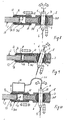
- the interchangeable elements may be a sleeve 6 wherein the syringe 3 and the probe 22 are introduced (Figs. 6, 7).
- the sleeves 6 have such an internal size and shape as to fit to the syringe 3 and to the probe 22.
- the internal size and shape of the sleeves 6 is such as to allow the syringe 3 and/or the probe 22 to slide in their axial direction.
- the syringe 3 may slide freely inside the hole formed in the case or in the sleeve 6, or with the help, for instance, of a combination of slides and guides provided on the outer surface of the syringe body 3 and on the inner surface of the hole 4 respectively, or vice versa. Alternatively or in combination, this construction may be provided also for the probe 22.
- means are provided for tilting the syringe 3 and the probe 22 substantially in all directions turned toward the body under examination C and in a substantially vertical direction relative to the latter, for the purpose of improving the possibilities to aim the needle 5 and the probe 22.
- These means consist of a spherical element 7, 7' which acts as a swinging suspension element housed in a corresponding spherical seat 108 formed inside the thickness of the case, but preferably inside a support element 8 which is in turn attached to the case of the receiving coil 2.
- This spherical elements 7, 7' have a through hole 4 for the syringe 3 and for the probe 22 to be introduced and slide therein.
- any other swinging suspension element may be provided, for instance a gimbal which, as is known, is a joint with two perpendicular oscillation axes, allowing motion in all directions.
- members may be provided to restrict the rotation of the elements 7, 7' inside the seat 108, e.g. small pads having such a construction as to generate a variable friction or one or more locking elements, or the like.
- Motor driven means may be further provided allowing the syringe 3 and/or the probe 22 both to slide and be tilted (Fig. 13).
- This means are illustrated only with respect to the syringe 3 but may be provided alternatively or at the same time also for the probe 22, the construction of the above mentioned means being essentially identical also for the probe 22.
- the said motor drive means there is provided a combination of at least one motor driven pinion 9 and at least one corresponding rack-like linear set of teeth, arranged axially on the outer surface of the syringe 3 or possibly of the sleeve 6 in which the syringe 3 and/or the probe 22 is held.
- an advantageous arrangement consists in that the syringe 3 and/or the probe 22 are secured in the sleeve 6, e.g. by means which prevent it from projecting on the side toward the patient C, which may consist, for instance, of a suitable annular flange 106, which causes the diameter of the sleeve 6 to narrow at its end turned toward the patient C.
- two rubber tracks may be provided on the surface thereof, each following half-meridians corresponding to perpendicular planes, whereon a small wheel splined on a driving motor or a gear 11 for engagement of a rack 107' shaped like a sector of a sphere 7, 7' rotates.
- several other mechanical displacement arrangements widely known per se, may be provided as an alternative thereto or in combination therewith.
- the supporting element 8 is provided with means allowing displacement in two directions which are substantially perpendicular to each other and to the axis of the syringe 3 when the latter is not in the tilted condition.
- the displacement in the first direction which is substantially radial with respect to the peripheral edge of the case is obtained by fitting the supporting element 8 at the external end of a carriage 12, particularly having a tubular shape, which is slidably engaged on guides 13.
- This movement may be motorized by providing a worm 14 which acts on an internally threaded bush 15, integral with the carriage 12.
- This bush 15 may be linked to a driving motor which causes the worm 14 to rotate and the carriage 12 to translate.
- the movement in the second direction which, as shown in Figs.
- 11 and 12 may be a substantially coincident or parallel direction with respect to the peripheral edge of the case or in a direction corresponding to a line secant or tangent to said edge, is obtained by arranging the guides 13 to be in turn carried by an additional carriage 16 slidably engaged on an additional pair of guides 17 provided within a supporting element 18 attached to the peripheral edge. It shall be understood that all the above mechanical displacement arrangements are only provided by way of example, any other prior art arrangement being allowed.
- All the guides illustrated herein, and particularly the translation guides 17 may be integrated in a hidden manner within the structure of the case of the receiving coil 2, as shown by the coils of Figs. 2 and 3.
- a slit allows the passage of a stirrup for connection with the carriage or the slide, sliding on the guide which follows the edge of the receiving coil.
- the diagnostic tool is an injection needle 23, particularly for injecting contrast agents. At the upper end, this has an element 19 for connection to a tube 20 linked to automatic dosing means 21 for supplying with a predetermined pressure the desired dose of contrast agent.
- Fig. 6 the guiding principle is shown as applied to a combined apparatus for simultaneous Magnetic Resonance and Ultrasound imaging.
- Each of the above diagnostic techniques has its own peculiar characteristics and is particularly suitable for imaging certain specific anatomic structures.
- the combined apparatuses tend to integrate both technologies, while trying to obtain as great an advantage as possible from each of them, for the purpose of obtaining as good a diagnostic image as possible, thanks to a good integration of the two images.
- they generally allow to precisely detect the position of the ultrasound probe 22 with respect to the MRI volume, both to obtain the desired appropriate integration of the two images and to focus with a high accuracy the transmission of ultrasounds.
- the therapeutic tool may consist in a further ultrasound probe used as an ultrasound source for emitting ultrasound energy having surgical or therapeutic action, for instance for the destructive action they can exert on neoplastic tissues or the like.
- a syringe 3 for injecting contrast agents and an ultrasound probe 22, particularly for irradiating a shoulder with sound, are provided in an support element 8 which is appropriately oversized as compared with the one described above.
- the seat for the probe 22 shall be adapted to the conformation thereof.
- the ultrasound probe 22 itself is provided with means 7' which allow it to be tilted, whereas translation is performed by means shared by the two instruments and like those described above.
- the probe may be arranged to be either of the manual operation and displacement type, or provided with its own separate means for displacement thereof along the part C under examination, distinct from those of the syringe 3.
- the signals from the ultrasound probe 22 and the receiving coil 2 may be advantageously processed with the well-known time sharing procedure which, as is known, provides that the electronic means for processing the received signals and for constructing a digital image formed by an array of pixels are at least partly the same for Magnetic Resonance signals and Ultrasound signals, particularly as regards equal imaging functions.
- These programs are executed alternately based on the type of corresponding received signal being processed from time to time.
- the means 8 for supporting the probe 22 may be such that the latter is at least partly located inside the MRI volume. This allows to integrate means for detecting the position of the probe 22 which may consist, for instance of one or more marking elements provided on the probe and recognizable by MRI.
- the needle or any other similar diagnostic or therapeutic tool and the ultrasound probe may be supported in a simultaneous and substantially identical manner by one or more of the arrangements provided in this description as regards the needle only and in any combination or subcombination thereof.
- any other diagnostic or therapeutic tool may be provided in lieu of the ultrasound probe.
- the ultrasound probe or any other tool and the needle or the like may be simultaneously supported in such a manner as to allow said two devices to be displaced with independent degrees of freedom or to only allow them to be displaced together with no possibility to change their relative position.
- the embodiment of Figs. 6 and 7 only allows the needle and the probe to be tilted in different manners.
- An additional example may consist in providing a construction as shown in Figs. 2, 3 and 11 and 12, wherein the same supporting member may be arranged to carry the needle or the like and the probe, the needle and the probe being only allowed to be displaced along the guide together and not independently from each other.
- At least one additional movable probe supporting member is provided, which is displaced, for instance, along the same translation guide for the needle support or the like, but is wholly independent and unlinked from the needle supporting member or the like.
Landscapes
- Health & Medical Sciences (AREA)
- Life Sciences & Earth Sciences (AREA)
- Physics & Mathematics (AREA)
- Nuclear Medicine, Radiotherapy & Molecular Imaging (AREA)
- Heart & Thoracic Surgery (AREA)
- Surgery (AREA)
- Biophysics (AREA)
- Pathology (AREA)
- Engineering & Computer Science (AREA)
- Biomedical Technology (AREA)
- Veterinary Medicine (AREA)
- Medical Informatics (AREA)
- Molecular Biology (AREA)
- Radiology & Medical Imaging (AREA)
- Animal Behavior & Ethology (AREA)
- General Health & Medical Sciences (AREA)
- Public Health (AREA)
- High Energy & Nuclear Physics (AREA)
- Condensed Matter Physics & Semiconductors (AREA)
- General Physics & Mathematics (AREA)
- Magnetic Resonance Imaging Apparatus (AREA)
- Ultra Sonic Daignosis Equipment (AREA)
Abstract
Description
Claims (41)
Applications Claiming Priority (2)
| Application Number | Priority Date | Filing Date | Title |
|---|---|---|---|
| ITSV20010029 | 2001-08-14 | ||
| IT2001SV000029A ITSV20010029A1 (en) | 2001-08-14 | 2001-08-14 | NUCLEAR MAGNETIC RESONANCE IMAGE DETECTION MRI (MRI) |
Publications (3)
| Publication Number | Publication Date |
|---|---|
| EP1286172A2 true EP1286172A2 (en) | 2003-02-26 |
| EP1286172A3 EP1286172A3 (en) | 2004-12-01 |
| EP1286172B1 EP1286172B1 (en) | 2011-02-16 |
Family
ID=11457103
Family Applications (1)
| Application Number | Title | Priority Date | Filing Date |
|---|---|---|---|
| EP02018005A Expired - Lifetime EP1286172B1 (en) | 2001-08-14 | 2002-08-12 | Magnetic resonance and ultrasound imaging apparatus |
Country Status (6)
| Country | Link |
|---|---|
| US (1) | US7676256B2 (en) |
| EP (1) | EP1286172B1 (en) |
| AT (1) | ATE498844T1 (en) |
| DE (1) | DE60239176D1 (en) |
| ES (1) | ES2361395T3 (en) |
| IT (1) | ITSV20010029A1 (en) |
Cited By (5)
| Publication number | Priority date | Publication date | Assignee | Title |
|---|---|---|---|---|
| EP1477115A1 (en) * | 2003-05-12 | 2004-11-17 | Hitachi, Ltd. | Surgical operation apparatus |
| WO2008018054A3 (en) * | 2006-08-08 | 2008-09-25 | Keter Medical Ltd | Imaging system |
| EP2277450A1 (en) * | 2009-07-23 | 2011-01-26 | Siemens Schweiz AG | Device for supporting at least one ultrasonic probe |
| WO2011083426A1 (en) * | 2010-01-07 | 2011-07-14 | Koninklijke Philips Electronics N.V. | Rf transmit and/or receive antenna for a hybrid mri / hifu system |
| EP2185078A4 (en) * | 2007-08-03 | 2012-05-09 | Innoscion Llc | REMOTELY WIRELESS OR WIRELESS REMOTE ULTRASONIC TRANSDUCER AND IMAGING APPARATUS |
Families Citing this family (14)
| Publication number | Priority date | Publication date | Assignee | Title |
|---|---|---|---|---|
| US6912050B2 (en) * | 2003-02-03 | 2005-06-28 | Hach Company | Phase shift measurement for luminescent light |
| EP1699354A4 (en) * | 2003-12-30 | 2011-01-05 | Medicis Technologies Corp | Systems and methods for the destruction of adipose tissue |
| US7857773B2 (en) * | 2003-12-30 | 2010-12-28 | Medicis Technologies Corporation | Apparatus and methods for the destruction of adipose tissue |
| GB2425610A (en) * | 2005-04-29 | 2006-11-01 | Univ London | Magnetic properties sensing system |
| JP5582739B2 (en) * | 2008-09-09 | 2014-09-03 | 株式会社東芝 | Magnetic resonance imaging apparatus and method for controlling magnetic resonance imaging apparatus |
| US9427186B2 (en) | 2009-12-04 | 2016-08-30 | Endomagnetics Ltd. | Magnetic probe apparatus |
| US10634741B2 (en) | 2009-12-04 | 2020-04-28 | Endomagnetics Ltd. | Magnetic probe apparatus |
| EP2516001A4 (en) * | 2009-12-24 | 2013-07-17 | Imris Inc | MRI AND ULTRASOUND GUIDED TREATMENT APPARATUS |
| CN105283202B (en) | 2013-03-11 | 2019-04-23 | 安都磁学有限公司 | Hypotonic solution for lymph node detection |
| US9239314B2 (en) | 2013-03-13 | 2016-01-19 | Endomagnetics Ltd. | Magnetic detector |
| US9234877B2 (en) | 2013-03-13 | 2016-01-12 | Endomagnetics Ltd. | Magnetic detector |
| ES2833377T3 (en) | 2015-06-04 | 2021-06-15 | Endomagnetics Ltd | Marker Materials and Ways to Locate a Magnetic Marker |
| WO2017175315A1 (en) * | 2016-04-05 | 2017-10-12 | 株式会社島津製作所 | Radiograph diagnosis device, method for associating radiograph and analysis result, and radiograph diagnosis system |
| CN113702883B (en) * | 2020-05-21 | 2024-07-16 | 中原工学院 | Intracavity magnetic resonance radio frequency coil and using method thereof |
Citations (4)
| Publication number | Priority date | Publication date | Assignee | Title |
|---|---|---|---|---|
| JPH0994233A (en) | 1995-09-29 | 1997-04-08 | Olympus Optical Co Ltd | Treatment apparatus |
| US5706812A (en) | 1995-11-24 | 1998-01-13 | Diagnostic Instruments, Inc. | Stereotactic MRI breast biopsy coil and method for use |
| WO2001001845A2 (en) | 1999-07-02 | 2001-01-11 | Ultraguide Ltd. | Apparatus and methods for medical interventions |
| EP1090594A1 (en) | 1999-10-05 | 2001-04-11 | GE Yokogawa Medical Systems Ltd. | Puncture needle support tool, RF coil, magnetic resonance signal measuring apparatus, and magnetic resonance imaging apparatus and method |
Family Cites Families (17)
| Publication number | Priority date | Publication date | Assignee | Title |
|---|---|---|---|---|
| US5240011A (en) * | 1991-11-27 | 1993-08-31 | Fischer Imaging Corporation | Motorized biopsy needle positioner |
| US5143068A (en) * | 1990-11-26 | 1992-09-01 | Resonex, Inc. | Flexible and curved radio frequency (RF) coil for the human shoulder for magnetic resonance imaging apparatus |
| US5176646A (en) * | 1991-02-19 | 1993-01-05 | Takayuki Kuroda | Motorized syringe pump |
| JP3325300B2 (en) * | 1992-02-28 | 2002-09-17 | 株式会社東芝 | Ultrasound therapy equipment |
| US5575287A (en) * | 1993-01-25 | 1996-11-19 | Fonar Corporation | Inductively coupled RF coils for magnetic resonance studies |
| BE1007459A3 (en) * | 1993-08-24 | 1995-07-04 | Philips Electronics Nv | A magnetic resonance apparatus. |
| US5471988A (en) * | 1993-12-24 | 1995-12-05 | Olympus Optical Co., Ltd. | Ultrasonic diagnosis and therapy system in which focusing point of therapeutic ultrasonic wave is locked at predetermined position within observation ultrasonic scanning range |
| US6019724A (en) * | 1995-02-22 | 2000-02-01 | Gronningsaeter; Aage | Method for ultrasound guidance during clinical procedures |
| US5817106A (en) * | 1995-09-19 | 1998-10-06 | Real; Douglas D. | Stereotactic guide apparatus for use with neurosurgical headframe |
| DE19732783C1 (en) * | 1997-07-30 | 1999-03-04 | Bruker Medizintech | RF coil system for an MR measuring device |
| DE69828011T2 (en) * | 1997-09-26 | 2005-12-01 | Koninklijke Philips Electronics N.V. | Device for holding a surgical instrument |
| ZA9811087B (en) * | 1997-12-04 | 1999-06-03 | Bracco Research Sa | Automatic liquid injection system and method |
| US5957934A (en) * | 1997-12-22 | 1999-09-28 | Uri Rapoport | Method and apparatus for guiding a penetrating tool into a three-dimensional object |
| AU1525400A (en) * | 1998-11-18 | 2000-06-05 | Microdexterity Systems, Inc. | Medical manipulator for use with an imaging device |
| JP4955172B2 (en) * | 1999-12-15 | 2012-06-20 | コーニンクレッカ フィリップス エレクトロニクス エヌ ヴィ | Diagnostic imaging system with ultrasound probe |
| ITSV20010020A1 (en) * | 2001-06-08 | 2002-12-08 | Esaote Spa | MACHINE FOR THE ACQUISITION OF IMAGES OF THE INTERNAL AREA OF A BODY IN PARTICULAR FOR THE ACQUISITION OF DIAGNOSTIC IMAGES |
| WO2003032837A1 (en) * | 2001-10-12 | 2003-04-24 | University Of Florida | Computer controlled guidance of a biopsy needle |
-
2001
- 2001-08-14 IT IT2001SV000029A patent/ITSV20010029A1/en unknown
-
2002
- 2002-08-12 DE DE60239176T patent/DE60239176D1/en not_active Expired - Lifetime
- 2002-08-12 EP EP02018005A patent/EP1286172B1/en not_active Expired - Lifetime
- 2002-08-12 ES ES02018005T patent/ES2361395T3/en not_active Expired - Lifetime
- 2002-08-12 AT AT02018005T patent/ATE498844T1/en not_active IP Right Cessation
- 2002-08-13 US US10/216,887 patent/US7676256B2/en not_active Expired - Lifetime
Patent Citations (4)
| Publication number | Priority date | Publication date | Assignee | Title |
|---|---|---|---|---|
| JPH0994233A (en) | 1995-09-29 | 1997-04-08 | Olympus Optical Co Ltd | Treatment apparatus |
| US5706812A (en) | 1995-11-24 | 1998-01-13 | Diagnostic Instruments, Inc. | Stereotactic MRI breast biopsy coil and method for use |
| WO2001001845A2 (en) | 1999-07-02 | 2001-01-11 | Ultraguide Ltd. | Apparatus and methods for medical interventions |
| EP1090594A1 (en) | 1999-10-05 | 2001-04-11 | GE Yokogawa Medical Systems Ltd. | Puncture needle support tool, RF coil, magnetic resonance signal measuring apparatus, and magnetic resonance imaging apparatus and method |
Cited By (8)
| Publication number | Priority date | Publication date | Assignee | Title |
|---|---|---|---|---|
| EP1477115A1 (en) * | 2003-05-12 | 2004-11-17 | Hitachi, Ltd. | Surgical operation apparatus |
| JP2004329726A (en) * | 2003-05-12 | 2004-11-25 | Hitachi Ltd | Surgical equipment |
| WO2008018054A3 (en) * | 2006-08-08 | 2008-09-25 | Keter Medical Ltd | Imaging system |
| EP2185078A4 (en) * | 2007-08-03 | 2012-05-09 | Innoscion Llc | REMOTELY WIRELESS OR WIRELESS REMOTE ULTRASONIC TRANSDUCER AND IMAGING APPARATUS |
| EP2277450A1 (en) * | 2009-07-23 | 2011-01-26 | Siemens Schweiz AG | Device for supporting at least one ultrasonic probe |
| WO2011009741A1 (en) * | 2009-07-23 | 2011-01-27 | Siemens Schweiz Ag | Device for holding at least one ultrasound probe |
| WO2011083426A1 (en) * | 2010-01-07 | 2011-07-14 | Koninklijke Philips Electronics N.V. | Rf transmit and/or receive antenna for a hybrid mri / hifu system |
| US9146290B2 (en) | 2010-01-07 | 2015-09-29 | Koninklijke Philips N.V. | RF transmit and/or receive antenna for a hybrid MRI/HIFU system |
Also Published As
| Publication number | Publication date |
|---|---|
| ITSV20010029A1 (en) | 2003-02-14 |
| US7676256B2 (en) | 2010-03-09 |
| ES2361395T3 (en) | 2011-06-16 |
| US20030083572A1 (en) | 2003-05-01 |
| EP1286172A3 (en) | 2004-12-01 |
| DE60239176D1 (en) | 2011-03-31 |
| EP1286172B1 (en) | 2011-02-16 |
| ATE498844T1 (en) | 2011-03-15 |
Similar Documents
| Publication | Publication Date | Title |
|---|---|---|
| US7676256B2 (en) | Imaging apparatus | |
| US6185445B1 (en) | MR tomograph comprising a positioning system for the exact determination of the position of a manually guided manipulator | |
| EP1410764B1 (en) | Positioning device for an mri compatible biopsy device | |
| US11504154B2 (en) | Transperineal imaging-guided prostate needle placement | |
| US9526515B2 (en) | Device for positioning an ultrasound transducer inside a MR scanner | |
| EP3618720B1 (en) | Transperineal stepper including rotatable transducer probe and shaft with internal cable | |
| US7066889B2 (en) | Scanning probe | |
| EP0967915B1 (en) | Method and system for positioning a magnetic resonance visible device | |
| KR100972709B1 (en) | MRI-induced ultrasound therapy device | |
| US20140275979A1 (en) | Needle placement manipulator with two rotary guides | |
| EP1264577A1 (en) | Apparatus combining different diagnostic imaging modalities | |
| US20140275978A1 (en) | Needle placement manipulator with attachment for rf-coil | |
| CN100366217C (en) | Disposal appliances and magnetic resonance imaging devices | |
| WO2005067392A2 (en) | Mri probe for prostate imaging | |
| Coutts et al. | Integrated and interactive position tracking and imaging of interventional tools and internal devices using small fiducial receiver coils | |
| Tsekos et al. | Development of a robotic device for MRI-guided interventions in the breast | |
| JP4049869B2 (en) | Nuclear magnetic resonance imaging system | |
| CN113893036A (en) | An interventional robotic device in a magnetic resonance environment | |
| Krieger et al. | Design and preliminary accuracy studies of an MRI-guided transrectal prostate intervention system | |
| JP3728437B2 (en) | Manipulator for use in closed magnetic resonance tomography equipment | |
| KR102513474B1 (en) | Ultrasonic imaging device and moving unit applying the same |
Legal Events
| Date | Code | Title | Description |
|---|---|---|---|
| PUAI | Public reference made under article 153(3) epc to a published international application that has entered the european phase |
Free format text: ORIGINAL CODE: 0009012 |
|
| AK | Designated contracting states |
Kind code of ref document: A2 Designated state(s): AT BE BG CH CY CZ DE DK EE ES FI FR GB GR IE IT LI LU MC NL PT SE SK TR Designated state(s): AT BE BG CH CY CZ DE DK EE ES FI FR GB GR IE IT LI LU MC NL PT SE SK TR |
|
| AX | Request for extension of the european patent |
Extension state: AL LT LV MK RO SI |
|
| PUAL | Search report despatched |
Free format text: ORIGINAL CODE: 0009013 |
|
| AK | Designated contracting states |
Kind code of ref document: A3 Designated state(s): AT BE BG CH CY CZ DE DK EE ES FI FR GB GR IE IT LI LU MC NL PT SE SK TR |
|
| AX | Request for extension of the european patent |
Extension state: AL LT LV MK RO SI |
|
| RIC1 | Information provided on ipc code assigned before grant |
Ipc: 7G 01R 33/28 B Ipc: 7A 61B 19/00 B Ipc: 7A 61B 17/34 B Ipc: 7G 01R 33/34 A |
|
| 17P | Request for examination filed |
Effective date: 20050517 |
|
| AKX | Designation fees paid |
Designated state(s): AT BE BG CH CY CZ DE DK EE ES FI FR GB GR IE IT LI LU MC NL PT SE SK TR |
|
| RAP1 | Party data changed (applicant data changed or rights of an application transferred) |
Owner name: ESAOTE S.P.A. |
|
| RAP1 | Party data changed (applicant data changed or rights of an application transferred) |
Owner name: ESAOTE S.P.A. |
|
| RAP1 | Party data changed (applicant data changed or rights of an application transferred) |
Owner name: ESAOTE S.P.A. |
|
| 17Q | First examination report despatched |
Effective date: 20090917 |
|
| GRAP | Despatch of communication of intention to grant a patent |
Free format text: ORIGINAL CODE: EPIDOSNIGR1 |
|
| GRAS | Grant fee paid |
Free format text: ORIGINAL CODE: EPIDOSNIGR3 |
|
| GRAA | (expected) grant |
Free format text: ORIGINAL CODE: 0009210 |
|
| AK | Designated contracting states |
Kind code of ref document: B1 Designated state(s): AT BE BG CH CY CZ DE DK EE ES FI FR GB GR IE IT LI LU MC NL PT SE SK TR |
|
| REG | Reference to a national code |
Ref country code: GB Ref legal event code: FG4D |
|
| REG | Reference to a national code |
Ref country code: CH Ref legal event code: EP |
|
| REG | Reference to a national code |
Ref country code: IE Ref legal event code: FG4D |
|
| REF | Corresponds to: |
Ref document number: 60239176 Country of ref document: DE Date of ref document: 20110331 Kind code of ref document: P |
|
| REG | Reference to a national code |
Ref country code: DE Ref legal event code: R096 Ref document number: 60239176 Country of ref document: DE Effective date: 20110331 |
|
| REG | Reference to a national code |
Ref country code: NL Ref legal event code: VDEP Effective date: 20110216 |
|
| REG | Reference to a national code |
Ref country code: ES Ref legal event code: FG2A Ref document number: 2361395 Country of ref document: ES Kind code of ref document: T3 Effective date: 20110616 |
|
| PG25 | Lapsed in a contracting state [announced via postgrant information from national office to epo] |
Ref country code: SE Free format text: LAPSE BECAUSE OF FAILURE TO SUBMIT A TRANSLATION OF THE DESCRIPTION OR TO PAY THE FEE WITHIN THE PRESCRIBED TIME-LIMIT Effective date: 20110216 Ref country code: GR Free format text: LAPSE BECAUSE OF FAILURE TO SUBMIT A TRANSLATION OF THE DESCRIPTION OR TO PAY THE FEE WITHIN THE PRESCRIBED TIME-LIMIT Effective date: 20110517 Ref country code: PT Free format text: LAPSE BECAUSE OF FAILURE TO SUBMIT A TRANSLATION OF THE DESCRIPTION OR TO PAY THE FEE WITHIN THE PRESCRIBED TIME-LIMIT Effective date: 20110616 |
|
| PG25 | Lapsed in a contracting state [announced via postgrant information from national office to epo] |
Ref country code: BE Free format text: LAPSE BECAUSE OF FAILURE TO SUBMIT A TRANSLATION OF THE DESCRIPTION OR TO PAY THE FEE WITHIN THE PRESCRIBED TIME-LIMIT Effective date: 20110216 Ref country code: AT Free format text: LAPSE BECAUSE OF FAILURE TO SUBMIT A TRANSLATION OF THE DESCRIPTION OR TO PAY THE FEE WITHIN THE PRESCRIBED TIME-LIMIT Effective date: 20110216 Ref country code: NL Free format text: LAPSE BECAUSE OF FAILURE TO SUBMIT A TRANSLATION OF THE DESCRIPTION OR TO PAY THE FEE WITHIN THE PRESCRIBED TIME-LIMIT Effective date: 20110216 Ref country code: BG Free format text: LAPSE BECAUSE OF FAILURE TO SUBMIT A TRANSLATION OF THE DESCRIPTION OR TO PAY THE FEE WITHIN THE PRESCRIBED TIME-LIMIT Effective date: 20110516 Ref country code: CY Free format text: LAPSE BECAUSE OF FAILURE TO SUBMIT A TRANSLATION OF THE DESCRIPTION OR TO PAY THE FEE WITHIN THE PRESCRIBED TIME-LIMIT Effective date: 20110216 Ref country code: FI Free format text: LAPSE BECAUSE OF FAILURE TO SUBMIT A TRANSLATION OF THE DESCRIPTION OR TO PAY THE FEE WITHIN THE PRESCRIBED TIME-LIMIT Effective date: 20110216 |
|
| PG25 | Lapsed in a contracting state [announced via postgrant information from national office to epo] |
Ref country code: DK Free format text: LAPSE BECAUSE OF FAILURE TO SUBMIT A TRANSLATION OF THE DESCRIPTION OR TO PAY THE FEE WITHIN THE PRESCRIBED TIME-LIMIT Effective date: 20110216 Ref country code: EE Free format text: LAPSE BECAUSE OF FAILURE TO SUBMIT A TRANSLATION OF THE DESCRIPTION OR TO PAY THE FEE WITHIN THE PRESCRIBED TIME-LIMIT Effective date: 20110216 |
|
| PGFP | Annual fee paid to national office [announced via postgrant information from national office to epo] |
Ref country code: FR Payment date: 20110802 Year of fee payment: 10 |
|
| PG25 | Lapsed in a contracting state [announced via postgrant information from national office to epo] |
Ref country code: SK Free format text: LAPSE BECAUSE OF FAILURE TO SUBMIT A TRANSLATION OF THE DESCRIPTION OR TO PAY THE FEE WITHIN THE PRESCRIBED TIME-LIMIT Effective date: 20110216 Ref country code: CZ Free format text: LAPSE BECAUSE OF FAILURE TO SUBMIT A TRANSLATION OF THE DESCRIPTION OR TO PAY THE FEE WITHIN THE PRESCRIBED TIME-LIMIT Effective date: 20110216 |
|
| PGFP | Annual fee paid to national office [announced via postgrant information from national office to epo] |
Ref country code: ES Payment date: 20110714 Year of fee payment: 10 Ref country code: GB Payment date: 20110720 Year of fee payment: 10 |
|
| PLBE | No opposition filed within time limit |
Free format text: ORIGINAL CODE: 0009261 |
|
| STAA | Information on the status of an ep patent application or granted ep patent |
Free format text: STATUS: NO OPPOSITION FILED WITHIN TIME LIMIT |
|
| 26N | No opposition filed |
Effective date: 20111117 |
|
| REG | Reference to a national code |
Ref country code: DE Ref legal event code: R097 Ref document number: 60239176 Country of ref document: DE Effective date: 20111117 |
|
| PG25 | Lapsed in a contracting state [announced via postgrant information from national office to epo] |
Ref country code: MC Free format text: LAPSE BECAUSE OF NON-PAYMENT OF DUE FEES Effective date: 20110831 |
|
| REG | Reference to a national code |
Ref country code: CH Ref legal event code: PL |
|
| PG25 | Lapsed in a contracting state [announced via postgrant information from national office to epo] |
Ref country code: CH Free format text: LAPSE BECAUSE OF NON-PAYMENT OF DUE FEES Effective date: 20110831 Ref country code: LI Free format text: LAPSE BECAUSE OF NON-PAYMENT OF DUE FEES Effective date: 20110831 |
|
| REG | Reference to a national code |
Ref country code: IE Ref legal event code: MM4A |
|
| PG25 | Lapsed in a contracting state [announced via postgrant information from national office to epo] |
Ref country code: IE Free format text: LAPSE BECAUSE OF NON-PAYMENT OF DUE FEES Effective date: 20110812 |
|
| GBPC | Gb: european patent ceased through non-payment of renewal fee |
Effective date: 20120812 |
|
| REG | Reference to a national code |
Ref country code: FR Ref legal event code: ST Effective date: 20130430 |
|
| PG25 | Lapsed in a contracting state [announced via postgrant information from national office to epo] |
Ref country code: LU Free format text: LAPSE BECAUSE OF NON-PAYMENT OF DUE FEES Effective date: 20110812 |
|
| PG25 | Lapsed in a contracting state [announced via postgrant information from national office to epo] |
Ref country code: GB Free format text: LAPSE BECAUSE OF NON-PAYMENT OF DUE FEES Effective date: 20120812 |
|
| PG25 | Lapsed in a contracting state [announced via postgrant information from national office to epo] |
Ref country code: FR Free format text: LAPSE BECAUSE OF NON-PAYMENT OF DUE FEES Effective date: 20120831 |
|
| PG25 | Lapsed in a contracting state [announced via postgrant information from national office to epo] |
Ref country code: TR Free format text: LAPSE BECAUSE OF FAILURE TO SUBMIT A TRANSLATION OF THE DESCRIPTION OR TO PAY THE FEE WITHIN THE PRESCRIBED TIME-LIMIT Effective date: 20110216 |
|
| REG | Reference to a national code |
Ref country code: ES Ref legal event code: FD2A Effective date: 20131021 |
|
| PG25 | Lapsed in a contracting state [announced via postgrant information from national office to epo] |
Ref country code: ES Free format text: LAPSE BECAUSE OF NON-PAYMENT OF DUE FEES Effective date: 20120813 |
|
| PGFP | Annual fee paid to national office [announced via postgrant information from national office to epo] |
Ref country code: IT Payment date: 20210805 Year of fee payment: 20 |
|
| PGFP | Annual fee paid to national office [announced via postgrant information from national office to epo] |
Ref country code: DE Payment date: 20210805 Year of fee payment: 20 |
|
| REG | Reference to a national code |
Ref country code: DE Ref legal event code: R071 Ref document number: 60239176 Country of ref document: DE |