EP1286146A1 - Load cell - Google Patents
Load cell Download PDFInfo
- Publication number
- EP1286146A1 EP1286146A1 EP01934439A EP01934439A EP1286146A1 EP 1286146 A1 EP1286146 A1 EP 1286146A1 EP 01934439 A EP01934439 A EP 01934439A EP 01934439 A EP01934439 A EP 01934439A EP 1286146 A1 EP1286146 A1 EP 1286146A1
- Authority
- EP
- European Patent Office
- Prior art keywords
- strain body
- strain
- load cell
- coating film
- resin
- Prior art date
- Legal status (The legal status is an assumption and is not a legal conclusion. Google has not performed a legal analysis and makes no representation as to the accuracy of the status listed.)
- Withdrawn
Links
- 239000011248 coating agent Substances 0.000 claims abstract description 110
- 238000000576 coating method Methods 0.000 claims abstract description 109
- 229920005989 resin Polymers 0.000 claims abstract description 75
- 239000011347 resin Substances 0.000 claims abstract description 75
- 239000011247 coating layer Substances 0.000 claims abstract description 39
- 239000007769 metal material Substances 0.000 claims abstract description 17
- 230000009477 glass transition Effects 0.000 claims abstract description 11
- 229910052782 aluminium Inorganic materials 0.000 claims description 29
- XAGFODPZIPBFFR-UHFFFAOYSA-N aluminium Chemical compound [Al] XAGFODPZIPBFFR-UHFFFAOYSA-N 0.000 claims description 29
- 239000010410 layer Substances 0.000 claims description 21
- 239000011256 inorganic filler Substances 0.000 claims description 17
- 229910003475 inorganic filler Inorganic materials 0.000 claims description 17
- -1 acryl Chemical group 0.000 claims description 15
- 238000012412 chemical coupling Methods 0.000 claims description 5
- 239000002245 particle Substances 0.000 claims description 5
- BLRPTPMANUNPDV-UHFFFAOYSA-N Silane Chemical compound [SiH4] BLRPTPMANUNPDV-UHFFFAOYSA-N 0.000 claims description 3
- 229910000077 silane Inorganic materials 0.000 claims description 3
- 229910052751 metal Inorganic materials 0.000 description 39
- 239000002184 metal Substances 0.000 description 39
- 230000007797 corrosion Effects 0.000 description 36
- 238000005260 corrosion Methods 0.000 description 36
- 238000001514 detection method Methods 0.000 description 27
- 239000003973 paint Substances 0.000 description 27
- XLYOFNOQVPJJNP-UHFFFAOYSA-N water Substances O XLYOFNOQVPJJNP-UHFFFAOYSA-N 0.000 description 25
- 239000002585 base Substances 0.000 description 18
- 239000000463 material Substances 0.000 description 14
- 239000010935 stainless steel Substances 0.000 description 11
- 229910001220 stainless steel Inorganic materials 0.000 description 11
- 239000000919 ceramic Substances 0.000 description 10
- 230000000694 effects Effects 0.000 description 10
- 229910000838 Al alloy Inorganic materials 0.000 description 8
- 230000002411 adverse Effects 0.000 description 7
- 238000006073 displacement reaction Methods 0.000 description 7
- 230000008859 change Effects 0.000 description 6
- JEIPFZHSYJVQDO-UHFFFAOYSA-N iron(III) oxide Inorganic materials O=[Fe]O[Fe]=O JEIPFZHSYJVQDO-UHFFFAOYSA-N 0.000 description 6
- 238000012545 processing Methods 0.000 description 6
- 238000007743 anodising Methods 0.000 description 5
- QVGXLLKOCUKJST-UHFFFAOYSA-N atomic oxygen Chemical compound [O] QVGXLLKOCUKJST-UHFFFAOYSA-N 0.000 description 5
- 230000000873 masking effect Effects 0.000 description 5
- 229910052760 oxygen Inorganic materials 0.000 description 5
- 239000001301 oxygen Substances 0.000 description 5
- 238000012360 testing method Methods 0.000 description 5
- 238000011156 evaluation Methods 0.000 description 4
- 238000005259 measurement Methods 0.000 description 4
- 150000003839 salts Chemical class 0.000 description 4
- 239000007921 spray Substances 0.000 description 4
- 230000015572 biosynthetic process Effects 0.000 description 3
- 229920001971 elastomer Polymers 0.000 description 3
- 230000005611 electricity Effects 0.000 description 3
- 239000000945 filler Substances 0.000 description 3
- 238000010438 heat treatment Methods 0.000 description 3
- 238000009413 insulation Methods 0.000 description 3
- 238000000465 moulding Methods 0.000 description 3
- 229920002635 polyurethane Polymers 0.000 description 3
- 239000004814 polyurethane Substances 0.000 description 3
- 238000005507 spraying Methods 0.000 description 3
- 229920002818 (Hydroxyethyl)methacrylate Polymers 0.000 description 2
- WOBHKFSMXKNTIM-UHFFFAOYSA-N Hydroxyethyl methacrylate Chemical compound CC(=C)C(=O)OCCO WOBHKFSMXKNTIM-UHFFFAOYSA-N 0.000 description 2
- QAOWNCQODCNURD-UHFFFAOYSA-N Sulfuric acid Chemical compound OS(O)(=O)=O QAOWNCQODCNURD-UHFFFAOYSA-N 0.000 description 2
- 229920005549 butyl rubber Polymers 0.000 description 2
- 230000007547 defect Effects 0.000 description 2
- 239000000428 dust Substances 0.000 description 2
- 125000000524 functional group Chemical group 0.000 description 2
- 239000000203 mixture Substances 0.000 description 2
- 229920000620 organic polymer Polymers 0.000 description 2
- 229920001343 polytetrafluoroethylene Polymers 0.000 description 2
- 239000004810 polytetrafluoroethylene Substances 0.000 description 2
- 229920002050 silicone resin Polymers 0.000 description 2
- 239000007779 soft material Substances 0.000 description 2
- 238000004544 sputter deposition Methods 0.000 description 2
- 229920001187 thermosetting polymer Polymers 0.000 description 2
- 238000007740 vapor deposition Methods 0.000 description 2
- NIXOWILDQLNWCW-UHFFFAOYSA-M Acrylate Chemical compound [O-]C(=O)C=C NIXOWILDQLNWCW-UHFFFAOYSA-M 0.000 description 1
- 239000004640 Melamine resin Substances 0.000 description 1
- 229920000877 Melamine resin Polymers 0.000 description 1
- VVQNEPGJFQJSBK-UHFFFAOYSA-N Methyl methacrylate Chemical compound COC(=O)C(C)=C VVQNEPGJFQJSBK-UHFFFAOYSA-N 0.000 description 1
- VYPSYNLAJGMNEJ-UHFFFAOYSA-N Silicium dioxide Chemical compound O=[Si]=O VYPSYNLAJGMNEJ-UHFFFAOYSA-N 0.000 description 1
- 229910000831 Steel Inorganic materials 0.000 description 1
- 239000002253 acid Substances 0.000 description 1
- 239000012790 adhesive layer Substances 0.000 description 1
- 239000003513 alkali Substances 0.000 description 1
- 125000005233 alkylalcohol group Chemical group 0.000 description 1
- 239000010407 anodic oxide Substances 0.000 description 1
- 230000008901 benefit Effects 0.000 description 1
- 230000001588 bifunctional effect Effects 0.000 description 1
- 239000002131 composite material Substances 0.000 description 1
- 150000001875 compounds Chemical class 0.000 description 1
- 229920001577 copolymer Polymers 0.000 description 1
- 238000012937 correction Methods 0.000 description 1
- 238000004132 cross linking Methods 0.000 description 1
- 239000003431 cross linking reagent Substances 0.000 description 1
- 238000013461 design Methods 0.000 description 1
- 239000013013 elastic material Substances 0.000 description 1
- 239000010419 fine particle Substances 0.000 description 1
- 125000002887 hydroxy group Chemical group [H]O* 0.000 description 1
- 229920000592 inorganic polymer Polymers 0.000 description 1
- 239000012948 isocyanate Substances 0.000 description 1
- 230000007774 longterm Effects 0.000 description 1
- 238000004519 manufacturing process Methods 0.000 description 1
- 238000000034 method Methods 0.000 description 1
- 239000000178 monomer Substances 0.000 description 1
- 239000000615 nonconductor Substances 0.000 description 1
- TWNQGVIAIRXVLR-UHFFFAOYSA-N oxo(oxoalumanyloxy)alumane Chemical compound O=[Al]O[Al]=O TWNQGVIAIRXVLR-UHFFFAOYSA-N 0.000 description 1
- 229920011301 perfluoro alkoxyl alkane Polymers 0.000 description 1
- 229920013653 perfluoroalkoxyethylene Polymers 0.000 description 1
- 229920001296 polysiloxane Polymers 0.000 description 1
- 125000002924 primary amino group Chemical group [H]N([H])* 0.000 description 1
- 230000009467 reduction Effects 0.000 description 1
- 239000013535 sea water Substances 0.000 description 1
- 229910052814 silicon oxide Inorganic materials 0.000 description 1
- 239000010959 steel Substances 0.000 description 1
- 239000000126 substance Substances 0.000 description 1
- 238000005406 washing Methods 0.000 description 1
- 238000005303 weighing Methods 0.000 description 1
Images




Classifications
-
- G—PHYSICS
- G01—MEASURING; TESTING
- G01G—WEIGHING
- G01G3/00—Weighing apparatus characterised by the use of elastically-deformable members, e.g. spring balances
- G01G3/12—Weighing apparatus characterised by the use of elastically-deformable members, e.g. spring balances wherein the weighing element is in the form of a solid body stressed by pressure or tension during weighing
- G01G3/14—Weighing apparatus characterised by the use of elastically-deformable members, e.g. spring balances wherein the weighing element is in the form of a solid body stressed by pressure or tension during weighing measuring variations of electrical resistance
-
- G—PHYSICS
- G01—MEASURING; TESTING
- G01L—MEASURING FORCE, STRESS, TORQUE, WORK, MECHANICAL POWER, MECHANICAL EFFICIENCY, OR FLUID PRESSURE
- G01L1/00—Measuring force or stress, in general
- G01L1/20—Measuring force or stress, in general by measuring variations in ohmic resistance of solid materials or of electrically-conductive fluids; by making use of electrokinetic cells, i.e. liquid-containing cells wherein an electrical potential is produced or varied upon the application of stress
- G01L1/22—Measuring force or stress, in general by measuring variations in ohmic resistance of solid materials or of electrically-conductive fluids; by making use of electrokinetic cells, i.e. liquid-containing cells wherein an electrical potential is produced or varied upon the application of stress using resistance strain gauges
- G01L1/2206—Special supports with preselected places to mount the resistance strain gauges; Mounting of supports
- G01L1/2243—Special supports with preselected places to mount the resistance strain gauges; Mounting of supports the supports being parallelogram-shaped
-
- G—PHYSICS
- G01—MEASURING; TESTING
- G01G—WEIGHING
- G01G3/00—Weighing apparatus characterised by the use of elastically-deformable members, e.g. spring balances
- G01G3/12—Weighing apparatus characterised by the use of elastically-deformable members, e.g. spring balances wherein the weighing element is in the form of a solid body stressed by pressure or tension during weighing
- G01G3/14—Weighing apparatus characterised by the use of elastically-deformable members, e.g. spring balances wherein the weighing element is in the form of a solid body stressed by pressure or tension during weighing measuring variations of electrical resistance
- G01G3/1402—Special supports with preselected places to mount the resistance strain gauges; Mounting of supports
- G01G3/1412—Special supports with preselected places to mount the resistance strain gauges; Mounting of supports the supports being parallelogram shaped
Definitions
- the present invention relates to a load cetl, and particularly to a load cell provided with a strain body and a sensor for detecting a displacement of the strain body caused by a load.
- a load cell used in a measuring device or the like has a strain body (i.e., a body to be strained) having a movable portion and a fixed portion, and a sensor for detecting a displacement of a strain body caused by a load applied thereto. A result of the detection is converted into a weight of a measuring target object, i.e., an object to be measured.
- a strain body i.e., a body to be strained
- a sensor for detecting a displacement of a strain body caused by a load applied thereto A result of the detection is converted into a weight of a measuring target object, i.e., an object to be measured.
- the movable portion of the strain body of the load cell is fixed to a support member supporting the measuring target object, or is fixed to a connection member, which connects the support member to the strain body, and will be referred to as a "measuring target side member” hereinafter.
- the fixed portion of the strain body is fixed to a fixed base or a connection member, which connects the fixed base to the fixed portion of the strain body, and will be referred to as a "fixed base side member” hereinafter.
- the strain body of the load cell is often made of aluminum or aluminum alloy primarily in view of demand for high precision and workability.
- the measuring target side member and the fixed base side member are primarily made of a material such as steel or stainless steel.
- a connection between the strain body and the measuring target side member as well as a connection between the strain body and the fixed base side member are in such a state that dissimilar metal materials are in electrically contact with each other. Therefore, if an atmosphere containing oxygen and/or moisture is present around these connections, electricity flows between the dissimilar metal materials to cause galvanic corrosion so that corrosion expands rapidly to reduce a lifetime of the load cell.
- the strain body may be made of stainless steel.
- the strain body may be coated with a molded material such as silicone or polyurethane.
- a molded material such as silicone or polyurethane.
- the molded material which is present between the member on the measuring target side or fixed base side and the strain body, deteriorates a weight detection precision due to viscoelastic properties of the molded material. If a molded material having a thickness from hundreds of micrometers to several millimeters is present between the member on the measuring target side or fixed base side and the strain body, this lowers the degree of fixing between the measuring target side member and the strain body as well as the degree of fixing between the fixed base side member and the strain body. Also, deformation of the molded material caused by the load deteriorates the weight detection precision. Accordingly, molding is effected on the strain body, which is already attached to the measuring target side member and the fixed base side member. However, this requires a complicated work for molding, and increases a working cost.
- the molding may be effected on the strain body alone while masking the movable portion and fixed portion. However, this cannot prevent the galvanic corrosion.
- the strain body may be covered with a box made of stainless steel after attaching the measuring target side member and the fixed base side member to the strain body.
- a box made of stainless steel after attaching the measuring target side member and the fixed base side member to the strain body.
- a film having an insulating property may be interposed between dissimilar metal materials. In this manner, however, water enters a fine space between the strain body and the film to cause corrosion.
- a member made of a relatively soft material may be interposed between dissimilar metal materials. In this manner, however, the load of the measuring target object is not transmitted 100% to the load cell so that an error occurs in a result of measurement.
- a scale including the strain body is used, e.g., in hot and humid surroundings or in a place exposed to salt-laden moisture of seawater or the like, corrosion occurs on the contact surfaces of dissimilar metal materials, and is also liable to occur on other surfaces.
- An object of the invention is to provide a load cell, which can suppress galvanic corrosion in a contact portion between the strain body and the member attached or connected to the strain body, and also can ensure a sufficient degree of fixing between the strain body and the member attached to the strain body so that a high weight detection precision can be achieved.
- an object of the invention is to provide a load cell, which has improved resistance to water, rust and corrosion, and can achieve high weight detection precision.
- a load cell includes a strain body, a bridge circuit and a coating film.
- the bridge circuit is formed of a strain gauge arranged on the strain body.
- the coating film is formed on the strain body, covers at least a portion of the strain body attached to a member made of a metal material dissimilar to the strain body, includes a coating layer made of resin having a glass transition temperature of 40°C or more, and has an electrical insulating property.
- a strain gaguge detects a displacement of the strain body caused by the load. Since the degree of displacement of the strain body depends on the magnitude of the load applied by a measuring target object, the weight of the measuring target object is obtained from the result of detection of the strain gauge.
- the coating film having the insulating property covers the portion of the strain body, to which the dissimilar metal member (i.e., the member made of a metal material dissimilar to the strain body) is attached, so as to prevent galvanic corrosion in such a case that the dissimilar metal member is in contact with the strain body.
- the coating film having the insulating property is interposed between the dissimilar metal member and the strain body. Therefore, an electricity hardly flows between the dissimilar metal member and the strain body, although these are made of different kinds of metal, respectively.
- the dissimilar metal member attached to the strain body may be a fixing member for fixing a portion of the strain body to the fixed base, a movable member for transmitting a load of the measuring target object to another portion of the strain body, a stop or limiter member such as a screw or a metal piece for restricting deformation of the strain body caused by an excessive load, and/or a board provided, e.g., with a line terminal portion between the strain gauge and external wiring and/or an amplifier for amplifying a strain gauge output.
- the strain body would be corroded due to a current flow between the dissimilar metal member and the strain body when oxygen and moisture were present therebetween.
- the coating film covers at least the portion of the strain body, which may be in contact with the dissimilar metal member. Therefore, the strain body is not in direct contact with the dissimilar metal member attached thereto, and is in contact with the same through the coating film. Since the coating film has the insulating property, a current does not flow between the dissimilar metal member and the strain body, and thus the flow between dissimilar metal materials is interrupted.
- the coating film is interposed between the strain body and the dissimilar metal member attached thereto the degree of fixing between the strain body and the dissimilar metal member may be lowered, and the weight detection precision may be adversely affected.
- these disadvantages are extremely smaller than the disadvantages caused by a thick molded member or other thick members for the insulation.
- the glass transition temperature is 40°C or more, and therefore the coating film is hard in a temperature range from -10°C to 40°C, which is an operation temperature range of this kind of scale.
- the coating film is extremely thin and hard, high weight detection precision can be maintained while insulating the strain body from the dissimilar metal member fixed or attached thereto and hardly affecting the degree of fixing of them.
- the strain gauge may be attached directly to the strain body, or may be formed on the strain body as disclosed in Japanese Patent No. 2,506,064.
- the coating film may be formed by application or by another manner such as vapor deposition or sputtering.
- the coating film of the load cell of the invention may be formed not only on the portion of the strain body to be in contact with the dissimilar metal, or may be formed of the whole surface of the strain body, as will be described later.
- the surface other than the surface in contact with the dissimilar metal may be coated with a film of the same material as that covering the dissimilar metal contact surface or a film of a different material.
- the portion other than the dissimilar metal contact portion may be molded with a conventional mold material.
- the coating film may be organic paint, or may be organic/inorganic hybrid paint (ceramic paint), as will be described later.
- acryl resin filled with an inorganic filler may be used-for the dissimilar metal contact surface, and a conventional rubber contained resin may be used for the other surface.
- the coating film layer is formed over the whole surface of the strain body, it is possible to interrupt the current between the strain body and the dissimilar metal member, and thereby to suppress corrosion of the strain body. Further, it is possible to suppress contact of oxygen and moisture in an atmosphere with the strain body, and thereby to suppress occurrence and progression of corrosion of the strain body. In this case, therefore, the resistance to water, rust and corrosion can be improved.
- an elastic material such as rubber or polyurethane has been used in a film, which coats the strain body for achieving intended resistance to water, rust and galvanic corrosion, in view of suppressing by the elasticity an influence on deformation of the strain body.
- a scale (measuring device) provided with a load cell of the same type as that of the present invention is generally used in a temperature range (i.c., operation temperature range) from -10°C to 40°C, and the elastic properties and viscosity properties of the foregoing material such as rubber or polyurethane have a temperature dependency in this operation temperature range. Particularly, if the weighing capacity is small (10 kg or lower), the viscosity properties exert a large influence, which cannot be substantially corrected.
- the coating layer is formed by coating the strain body surface with resin having a high glass transition temperature, i.e., with hard resin so as to suppress an adverse effect, which may be exerted on the change in electric resistance of the strain gauge by the load. Since the change in viscosity properties of this kind of resin is extremely small even in the above operation temperature range, it is possible to provide the load cell having high precision and good resistance to water.
- the strain body surface is coated with the resin having a high glass transition temperature, and thus the hard resin having an insulating property as described above. Therefore, no gap is present between the strain body and the coating film, and thus entry of water does not occur so that the load cell can have a good resistance to water.
- the load applied from the measuring target object is reliably transmitted.
- a load cell includes a strain body, a bridge circuit and a coating film.
- the bridge circuit is formed of a strain gauge arranged on the strain body.
- the coating film is formed on the strain body, covers at least a strain occurring portion of the strain body except for a portion attached to the strain gauge, includes a coating layer made of resin having a glass transition temperature of 40°C or more, and has an electrical insulating property.
- the coating film is not formed over the portion, to which the strain gauge is attached.
- such a manner may be employed that the paint is applied to the strain body while masking the portion to be used for attaching the strain gauge.
- the wiring and the strain gauge it is preferable to cover the wiring and the strain gauge with waterproof resin.
- the strain gauge and the wiring are covered with the waterproof resin covering at least the masked portion described before, such a situation can be suppressed that moisture in an atmosphere adversely affects the strain gauge and the wiring.
- the strain gauge is covered with the resin, the surface of the strain body (i.e., uncoated surface) is not exposed even at the vicinity of the strain gauge. This can further suppress occurrence and progression of corrosion of the strain body.
- strain gauge and the wiring may be covered, e.g., by applying silicone resin over a waterproof butyl rubber sheet.
- a load cell includes a strain body, a bridge circuit and a coating film.
- the bridge circuit is formed of a strain gauge arranged on the strain body.
- the coating film is formed on the strain body, covers at least a portion of the strain body attached to a member made of a metal material dissimilar to the strain body and a strain occurring portion of the strain body except for a portion to be attached to the strain gauge, includes a coating layer made of resin having a glass transition temperature of 40°C or more, and has an electrical insulating property.
- This aspect particularly relates to a structure, in which the coating film is formed at least over the dissimilar metal contact surface and the strain occurring portion other than the portion, to which the strain gauge is attached.
- the load cell of the third aspect further has such a feature that the resin of the coating layer is acryl resin.
- acryl resin is superior because it allows easy introduction of cross linkage as well as easy production of hybrid composition with inorganic filler, and also allows easy application for coating.
- the acryl resin is used for coating the strain body so that intended precision of the scale can be maintained without preventing galvanic corrosion, and further the strain body may have improved resistance to water.
- the acryl resin may be the same as that disclosed in pamphlet No. W096/34063. It is preferable to use (meth-) acrylate of lower alkyl alcohol, and is particularly preferable to use copolymer of methyl methacrylate and hydroxyethyl methacrylate.
- the load cell of the fourth aspect further has such a feature that the acryl resin is cross-linked to form a three-dimensional structure.
- the resin having the three-dimensional structure, which is produced by the cross-linking, is superior in stability of the coating layer against changes in environment, and particularly in resistance to water and moisture.
- the strain body is coated with such resin to provide the coating film having good resistance to water and moisture so that the strain body can have improved resistance to water.
- the resin having a high cross-link density is used so that the coating layer can be hard and resistant to a scratch or damage by an external force. Therefore, the strain body can keep intended resistance to rust for a long term.
- cross-links in the resin it is preferable to employ such a manner that a monomer (e.g., hydroxyethyl methacrylate) having a functional group capable of forming cross-links is partially copolymerized, a di-isocyanate compound is mixed in the resin, and a heat treatment is effected on the coating layer applied to the strain body.
- a monomer e.g., hydroxyethyl methacrylate
- a di-isocyanate compound is mixed in the resin, and a heat treatment is effected on the coating layer applied to the strain body.
- the load cell of the fifth aspect further has such a feature that the coating film further has an anodized aluminum layer, and the coating layer is formed on a surface of the anodized aluminum layer.
- the strain body is preferably made of aluminum in view of weight precision. If the strain body of aluminum is anodized, a corrosion-resistant oxide coating is formed over the surface of the aluminum, and many fine holes are formed at the surface of the strain body. These holes improve the adhesion of the coating layer to the strain body. Even when a damage is formed on the coating layer, the background layer formed of the hard anodized aluminum layer can prevent exposure of the aluminum alloy having low corrosion resistance. The anodizing in synergy with the application of the coating film effectively suppresses the galvanic corrosion, and can provide the rustproof performance.
- the resistance to acid and alkali, which cannot be sufficiently achieved by the anodizing alone, can be improved.
- the electrical insulating property of the anodized aluminum layer improves the electrical insulating properly in the whole coating film.
- Copper-contained aluminum alloy which is generally used in load cells, cannot have sufficient resistance to galvanic corrosion even if anodizing is effected on the surface because the anodized aluminum film thus formed have many defects.
- the coating layer is additionally formed on the surface of the anodized aluminum layer so that the coating layer fills the defects in the anodized aluminum film.
- the load cell of the sixth aspect further has such a feature that the coating film has a thickness equal to or larger than 1 ⁇ m and smaller than 100 ⁇ m.
- the coating film has the thickness not exceeding 100 ⁇ m so that an intended weight detection precision may be maintained by ensuring an intended degree of fixing between the strain body and the dissimilar metal member attached to the strain body.
- reduction in the degree of fixing which may be caused by the interposition of the coating film between the strain body and the dissimilar metal member, can be suppressed to an extent, which hardly affects the weight detection precision.
- the insulation is achieved by the coating film smaller than 100 ⁇ m in thickness so that the galvanic corrosion can be prevented while maintaining the weight detection precision.
- the appropriate thickness of the coating film depends on the kind and size of the load cell. If the thickness of the coating film were excessively small, and did not exceed one ⁇ m, a damage would often occur on the coating film so that the load cell could not have intended water resistance. If the thickness were larger than 100 ⁇ m, the detection precision of the sensor would be excessively low. Accordingly, the desired thickness is in a range from hundreds of micrometers to several millimeters. It is also preferable that the coating film has a uniform thickness.
- the load cell of the third aspect further has such a feature that inorganic filler having a particle diameter of 50 ⁇ m.or less is mixed in the resin of the coating layer.
- the resin containing the inorganic filler is further preferable because it has resistance to smearing in addition to a sufficient hardness.
- the above resin covers the strain body for maintaining the precision of the scale while preventing the galvanic corrosion.
- the inorganic filler is preferably formed of fine particles of aluminum oxide, silicon oxide or the like. It is preferable that the inorganic filler is uniformly dispersed in the resin. For this, the fine filler having a particle diameter of 50 ⁇ m is used, and is mixed in the resin at a rate from about 5% to about 60%.
- the load cell of the eighth aspect further has such a feature that the resin is acryl resin cross-linked to form a three-dimensional structure.
- This load cell can achieve operation and effect similar to those of the load cell of the fifth aspect.
- the load cell of the ninth aspect further has such a feature that the coating film further has an anodized aluminum layer, and a coating layer is formed on a surface of the anodized aluminum layer.
- This load cell can achieve operation and effect similar to those of the load cell of the sixth aspect.
- the load cell of the tenth aspect further has such a feature that the coating film has a thickness equal to or larger than 1 ⁇ m and smaller than 100 ⁇ m.
- This load cell can achieve operation and effect similar to those of the load cell of the seventh aspect.
- the load cell of the third aspect further has such a feature that the resin of the coating layer contains inorganic filler having a particle diameter of 50 ⁇ m or less, and the inorganic filler is combined with the resin by chemical coupling.
- Ceramic paint (organic/inorganic hybrid paint) is produced by combining organic and inorganic components by chemical coupling, which is introduced between the different components. As a result, the ceramic paint has the features of both the components.
- the density of cross-links between organic polymers is high, and the density of cross-links between organic and inorganic polymers is also high so that the coating film has a dense structure, and thus has high resistance to moisture and water. Accordingly, the coating layer made of such paint can improve the waterproof and rustproof performances.
- the coating layer made of the ceramic paint is hard, and is sufficiently resistant to a scratch or damage, which may be caused by an external force. Further, the inorganic components of the ceramic paint, which have resistance to smearing, weather and chemical attack, can further improve the rustproof performance of the coating layer.
- the coating layer is made of the ceramic paint so as to provide the surface of the strain body having appropriate hardness, smear resistance (affinity for water), electrical insulating property and others.
- the load cell of the twelfth aspect further has such a feature that a silane treatment is effected on a surface of the inorganic filler.
- the filler in the resin is chemically coupled with the resin to form composites, it promotes formation of the three-dimensional structure of the resin, and contributes to formation of a hard and stable coating film.
- predetermined processing and particularly, the silane processing is effected on the surface of inorganic filler so as to achieve chemical coupling with the resin.
- a functional group such as an amino or hydroxyl group is introduced into the filler surface.
- a heat treatment is effected after the application of the resin so that the chemical coupling between the inorganic filler and the resin can be promoted via a multifunctional (usually, bifunctional) compound (crosslinking agent) in the resin.
- the heat treatment is substantially performed at a temperature from 150 to 200°C for 10 to 30 minutes.
- Application of the resin is preferably performed by a spray, a brush or the like.
- the load cell of the thirteenth aspect further has such a feature that the resin is an acryl resin cross-linked to have a three-dimensional structure.
- This aspect relates to a case where the coating layer employs ceramic paint (organic/inorganic hybrid paint) made of the organic component of the acryl resin and the inorganic component of the inorganic filler.
- ceramic paint organic/inorganic hybrid paint
- the coating layer made of the organic/inorganic hybrid paint has an improved hardness.
- the strain body can have improved resistance to water, rust and corrosion.
- the load cell of the fourteenth aspect further has such a feature that the coating film further has an anodized aluminum layer, and the coating layer is formed over the surface of the anodized aluminum layer.
- the load cell of this aspect can achieve operation and effect similar to those of the load cells of the sixth and tenth aspects.
- the load cell of the fifteenth aspect further has such a feature that the coating film has a thickness equal to or larger than 1 ⁇ m and smaller than 100 ⁇ m.
- the load cell of this aspect can achieve operation and effect similar to those of the load cells of the seventh and eleventh aspects.
- a load cell 1 according to an embodiment of the invention is shown in Fig. 1.
- the load cell 1 is primarily formed of a strain body 2 and four strain gauges (sensors) 7.
- the strain body 2 has a fixed rigid portion 3 and a movable rigid portion 4 at its opposite ends, respectively, and these rigid portions 3 and 4 are coupled together by upper and lower (i.e., two) beams 5 and 6.
- the strain body 2 is primarily made of aluminum alloy.
- the two beams 5 and 6 are provided with thin strain measuring portions 5a and 6a located near the fixed rigid portion 3 as well as thin strain measuring portions 5b and 6b located near the movable rigid portion 4, respectively.
- the strain gauges 7 are attached or adhered as shown in Figs. 1 and 6, respectively.
- These strain gauges 7 are connected to a Wheatstone bridge, and can detect strains (degrees of deformation), which are caused in the strain body 2 by a load P applied to the movable rigid portion 4, in accordance with changes in electrical resistance.
- a load i.e., a weight of a measuring target object
- the load cell 1 is attached, e.g., to a fixed base 80 and a support member 90 supporting a measuring target object G, i.e., object to be measured, and forms a component of a scale.
- a measuring target object G i.e., object to be measured
- the fixed rigid portion 3 of the strain body 2 is attached to a fixed connection member 81 fixed to the fixed base 80, and the movable rigid portion 4 of the strain body 2 is attached to a movable connection member 91 fixed to the support member 90.
- the load P (see Fig. 1) of the measuring target object G acts on the movable rigid portion 4 of the strain body 2 via the movable connection member 91, and displaces the movable rigid portion 4 downward. Since the fixed rigid portion 3 is fixed to the fixed base 80, the strain body 2 deforms to extend the strain measuring portions 5a and 6b, and shrink the strain measuring portions 5b and 6a.
- the strain gauges 7 detect strains of the strain body 2 thus deformed.
- the fixed and movable connection members 81 and 91 are made of stainless steel, which is superior in resistance to rust and corrosion.
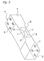
- the strain body 2 which-has-a-predetermined configuration shown in Fig. 3 and is made of aluminum alloy, is first subjected to processing of forming an anodic oxide film (anodized aluminum layer) in a sulfuric acid bath, and then is subjected to spray coating with organic/inorganic hybrid paint ("BELL CLEAN No. 1000" manufactured by NOF Corporation). After the spray coating, baking is performed at 190°C for 30 minutes so that a coating film 10 is formed as shown in Fig. 4. The baking processing is preferably performed at a temperature ranging from 150°C to 200°C for a time period ranging from 10 to 30 minutes after reaching a predetermined temperature.
- the whole surface of the strain body 2 is coated with the anodized aluminum layer and the coating layer.
- masking is effected on portions, on which the strain gauges 7 will be attached later, i.e., on an area A1 in an upper surface of the beam portion 5 and an area A2 in a lower surface of the beam portion 6.
- the coating film 10 is formed over the whole surface of the strain body 2 except for the areas A1 and A2, as shown in Fig. 4.
- the coating film 10 is formed over the portion except for portions, to which the strain gauges 7 are attached, and portions around these portions for the strain gauges 7 (i.e., areas A1 and A2).
- the coating with hard resin such as ceramic paint affects creep characteristics of the load cell 1.
- the creep characteristics are defined by a voltage changing phenomenon caused by changes in resistance of the strain gauge 7, which occur due to change in amount of strain determined by the strain gauge 7. This change in amount of strain occurs with time when the strain gauge 7 determines the deformation of the strain body 2 made of aluminum alloy or the like due to a load.
- a manner of appropriately combining a time constant of deformation of the strain body 2 and a time constant of the strain gauge 7 (including an adhesive layer and a coating agent) during determination of the strain is generally employed to provide a state, in which the strain amount determined by the strain gauge 7 does not depend on elapsing of time.
- the strain body 2 is coated with hard resin according to the present invention, the time constant of deformation of the strain body 2 changes. Therefore, for the operation, in which the change occurs in time constant of deformation of the strain body 2 caused by effects including an influence of the resin, the foregoing manners (2) and (3) are employed to change the time constant of the strain gauge 7 to produce the state, in which the strain amount determined by the strain gauge 7 is independent of the time elapsing.
- Fig. 5 fragmentarily shows a section of the strain body 2 coated with the coating film 10.
- the coating film 10 has a thickness equal to a sum of a thickness of 5 ⁇ m ⁇ 2 ⁇ m of the anodized aluminum layer and a thickness of 15 ⁇ m ⁇ 5 ⁇ m of the coating layer.
- the coating film 10 has an electrically insulating property, and will serve as an electrical insulator between the fixed rigid portion 3 (and movable rigid portion 4) and the fixed connection member 81 (movable connection member 91) fixed thereto by screws or the like in a later step.
- the fixed and movable rigid portions 3 and 4 are provided with screw holes 3a and 4a for fixing the fixed and movable connection members 81 and 91 by screws or the like.
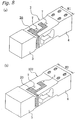
- the strain gauges 7 and a flexible printed board 20 are attached to the strain body 2 as shown in Fig. 6.
- a terminal of each strain gauge 7 is connected to wiring in the flexible printed board 20.
- the flexible printed board is employed for simplifying a wiring work for the strain gauges 7 and bridge circuit formed of resistances for output compensation and others.
- the strain body 2 made of copper-contained aluminum alloy of No. 2000 series was prepared, and then the anodizing was effected on the strain body 2, of which a portion used for attaching the strain gauges 7 is masked.
- the anodized portion of the strain body 2 was subjected to spray coating with organic/inorganic hybrid paint ("BELL CLEAN No. 1000" manufactured by NOF Corporation) to form the coating layer.
- the coating was also applied to screw portions near or around the screw holes 3a and 4a.
- application of the paint to these portions is not essential.
- the strain gauges 7 were attached to the strain body 2 (implementation example 1).
- strain body 2 was prepared and processed similarly to the implementation example 1 except for that a rubber-contained material ("SB243L” manufactured by Nitto Denko Corporation.) was used instead of the organic/inorganic hybrid paint (comparison example 1).
- SB243L a rubber-contained material manufactured by Nitto Denko Corporation.
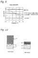
- an organic/inorganic hybrid paint and a conventional paint (clear paint in this example) 9 were applied to two aluminum plates, respectively, and then these two plates were adhered to the plates made of stainless steel SUS304.
- the former will be referred to as an "implementation example 2", and the latter will be referred to as a “comparison example 2").
- a flat head screw made of stainless steel was disposed between the aluminum plate and the stainless steel plate.
- reference numbers 11, 32 and 13 indicate the aluminum plate, stainless steel plate and flat head screw, respectively.
- the insulating coating film covers the portion of the strain body, to which the member (dissimilar metal member) made of the metal material dissimilar to the strain body is attached, for preventing the galvanic. corrosion of the strain body and the attached dissimilar metal member in contact with the. same. Therefore, an electricity hardly flows between the dissimilar metal members and the strain body, and the galvanic corrosion does not occur, although these are made of dissimilar metal materials.
- the coating film is extremely thin, it can insulate the strain body from the dissimilar metal member attached thereto without exerting a substantial influence on the degree of fixing between them, and the weight detection precision can be maintained high.
- the coating film contains the coating layer of the paint, of which base is made of hard resin. Therefore, the coating film can effectively maintain the weight detection precision while preventing the galvanic corrosion. In the portion not in contact with the dissimilar metal, the coating film can improve the water resistance.
Landscapes
- Physics & Mathematics (AREA)
- General Physics & Mathematics (AREA)
- Measurement Of Force In General (AREA)
- Measurement Of Length, Angles, Or The Like Using Electric Or Magnetic Means (AREA)
Abstract
Description
| Salt Water Spray Time (hr) | Implementation Example 2 (%) | Comparison Example 2 (%) |
| 0 | 0 | 0 |
| 200 | 80 | 5 |
Claims (16)
- A load cell comprising:a strain body;a bridge circuit formed of a strain gauge arranged on said strain body; anda coating film formed on said strain body, coveringat least a portion of said strain body attached to a member made of a metal material dissimilar to said strain body, said coating film having an electrical insulating property and including a coating layer made of resin having a glass transition temperature of 40°C or more.
- A load cell comprising:a strain body;a bridge circuit formed of a strain gauge arranged on said strain body; anda coating film formed on said strain body, covering at least a strain occurring portion of said strain body except for a portion attached to said strain gauge, said coating film having an electrical insulating property and including a coating layer made of resin having a glass transition temperature of 40°C or more.
- A load cell comprising:a strain body;a bridge circuit formed of a strain gauge arranged on said strain body; anda coating film formed on said strain body, covering at least a portion of the strain body attached to a member made of a metal material dissimilar to said strain body and a strain occurring portion of said strain body except for a portion attached to said strain gauge, said coating film having an electrical insulating property and including a coating layer made of resin having a glass transition temperature of 40°C or more.
- The load cell according to claim 3, wherein
said resin of the coating layer is acryl resin. - The load cell according to claim 4, wherein
said acryl resin is cross-linked to form a three-dimensional structure. - The load cell according to claim 5, wherein
said coating film further has an anodized aluminum layer, and said coating layer is formed on a surface of said anodized aluminum layer. - The load cell according to claim 6, wherein
said coating film has a thickness equal to or larger than 1 µm and smaller than 100 µm. - The load cell according to claim 3, wherein
inorganic filler having a particle diameter of 50 µm or less is mixed in the resin of said coating layer. - The load cell according to claim 8, wherein
said resin is acryl resin cross-linked to form a three-dimensional structure. - The load cell according to claim 9, wherein
said coating film further has an anodized aluminum layer, and said coating layer is formed on a surface of said anodized aluminum layer. - The load cell according to claim 10, wherein
said coating film has a thickness equal to or larger than 1 µm and smaller than 100 µm. - The load cell according to claim 3, wherein
said resin of the coating layer contains inorganic filler having a particle diameter of 50 µm or less, and said inorganic filler is combined with said resin by chemical coupling. - The load cell according to claim 12, wherein
a silane treatment is effected on a surface of said inorganic filler. - The load cell according to claim 13, wherein
said resin is an acryl resin cross-linked to have a three-dimensional structure. - The load cell according to claim 14, wherein
said coating film further has an anodized aluminum layer, and said coating layer is formed on a surface of said anodized aluminum layer. - The load cell according to claim 15, wherein
said coating film has a thickness equal to or larger than 1 µm and smaller than 100 µm.
Applications Claiming Priority (3)
| Application Number | Priority Date | Filing Date | Title |
|---|---|---|---|
| JP2000162125A JP2001343294A (en) | 2000-05-31 | 2000-05-31 | Load cell and scale |
| JP2000162125 | 2000-05-31 | ||
| PCT/JP2001/004574 WO2001092844A1 (en) | 2000-05-31 | 2001-05-30 | Load cell |
Publications (2)
| Publication Number | Publication Date |
|---|---|
| EP1286146A1 true EP1286146A1 (en) | 2003-02-26 |
| EP1286146A4 EP1286146A4 (en) | 2007-03-07 |
Family
ID=18666062
Family Applications (1)
| Application Number | Title | Priority Date | Filing Date |
|---|---|---|---|
| EP01934439A Withdrawn EP1286146A4 (en) | 2000-05-31 | 2001-05-30 | Load cell |
Country Status (10)
| Country | Link |
|---|---|
| US (1) | US6694829B2 (en) |
| EP (1) | EP1286146A4 (en) |
| JP (1) | JP2001343294A (en) |
| KR (1) | KR100793119B1 (en) |
| CN (1) | CN1177200C (en) |
| AU (1) | AU753160B2 (en) |
| CA (1) | CA2380470C (en) |
| NZ (1) | NZ516832A (en) |
| TW (1) | TW505778B (en) |
| WO (1) | WO2001092844A1 (en) |
Cited By (6)
| Publication number | Priority date | Publication date | Assignee | Title |
|---|---|---|---|---|
| WO2011115386A3 (en) * | 2010-03-18 | 2012-01-12 | 고려대학교 산학협력단 | Temperature compensation load cell having strain gauges |
| RU2469340C1 (en) * | 2011-05-23 | 2012-12-10 | Российская Федерация, от имени которой выступает Министерство промышленности и торговли Российской Федерации (Минпромторг России) | Method of correcting measurement results using tensometric bridge sensor with instrumentation amplifier |
| RU2469341C1 (en) * | 2011-05-23 | 2012-12-10 | Российская Федерация, от имени которой выступает Министерство промышленности и торговли Российской Федерации (Минпромторг России) | Measuring device |
| RU2469339C1 (en) * | 2011-05-23 | 2012-12-10 | Российская Федерация, от имени которой выступает Министерство промышленности и торговли Российской Федерации (Минпромторг России) | Measuring device |
| RU2469338C1 (en) * | 2011-05-23 | 2012-12-10 | Российская Федерация, от имени которой выступает Министерство промышленности и торговли Российской Федерации (Минпромторг России) | Measuring device |
| US10620061B2 (en) | 2016-11-21 | 2020-04-14 | Honeywell International Inc. | Vulcanized metal plug for high fatigue application for load pin |
Families Citing this family (23)
| Publication number | Priority date | Publication date | Assignee | Title |
|---|---|---|---|---|
| ATE301827T1 (en) * | 2002-03-18 | 2005-08-15 | Mettler Toledo Gmbh | FORCE TRANSDUCER, FORCE TRANSDUCER WITH A MOUNTING DEVICE AND SCALE. |
| US7685869B2 (en) * | 2006-03-13 | 2010-03-30 | Asylum Research Corporation | Nanoindenter |
| JP5052502B2 (en) * | 2007-02-02 | 2012-10-17 | 株式会社イシダ | Load cell |
| JP5019962B2 (en) * | 2007-06-13 | 2012-09-05 | 京都機械工具株式会社 | Torque Wrench |
| EP2185904A2 (en) * | 2007-08-27 | 2010-05-19 | Koninklijke Philips Electronics N.V. | Pressure sensor, sensor probe comprising a pressure sensor, medical apparatus comprising a sensor probe and a method of fabricating a sensor probe |
| DE102008064169B4 (en) * | 2008-12-22 | 2013-07-18 | Hottinger Baldwin Messtechnik Gmbh | load cell |
| WO2010106388A1 (en) * | 2009-03-19 | 2010-09-23 | S.C.A.I.M.E S.A. | Sealed sensor with strain gauges |
| US8161829B2 (en) * | 2009-07-28 | 2012-04-24 | Vishay Precision Group, Inc. | Circuit compensation in strain gage based transducers |
| EP3557210B1 (en) * | 2010-02-12 | 2022-12-14 | Proteor USA, LLC | Compact and robust load and moment sensor |
| CA2789584A1 (en) * | 2010-02-12 | 2011-08-18 | Freedom Innovations, L.L.C. | Novel enhanced methods for mimicking human gait with prosthetic knee devices |
| DE102010014152B4 (en) * | 2010-04-07 | 2015-12-24 | Hottinger Baldwin Messtechnik Gmbh | load cell |
| US9194735B2 (en) | 2012-03-16 | 2015-11-24 | Ishida Co., Ltd. | Combination weighing device initialization |
| JP5785123B2 (en) | 2012-03-16 | 2015-09-24 | 株式会社イシダ | Combination weighing device |
| DE202012003907U1 (en) * | 2012-04-19 | 2012-05-15 | Igus Gmbh | Monitoring system for tensile and compressive forces in an energy supply chain and corresponding force transducer |
| DE102012210021A1 (en) * | 2012-06-14 | 2013-12-19 | Tecsis Gmbh | Force sensor with a sensor plate with local differences in stiffness |
| CN103111803B (en) * | 2012-11-29 | 2015-05-20 | 汉中市如松弹性体有限责任公司 | Processing method of elastic body for sensor |
| JP6632817B2 (en) * | 2015-06-25 | 2020-01-22 | 大和製衡株式会社 | Parallelogram load cell |
| US10223482B2 (en) | 2016-06-29 | 2019-03-05 | International Business Machines Corporation | Machine learning assisted reservoir simulation |
| MX2019000251A (en) | 2016-07-05 | 2019-10-09 | Univ Johns Hopkins | Compositions and methods comprising improvements of crispr guide rnas using the h1 promoter. |
| US20180027777A1 (en) * | 2016-07-26 | 2018-02-01 | Stablesense, Inc. | Water consumption sensors and systems for equine applications |
| US10786202B2 (en) * | 2016-09-28 | 2020-09-29 | International Business Machines Corporation | Quantifying grip strength and characterizing movement idioms |
| US10959800B2 (en) * | 2016-11-08 | 2021-03-30 | Covidien Lp | Force sensors for surgical devices to prevent ingress of fluids |
| US10816419B2 (en) | 2019-01-25 | 2020-10-27 | FUTEK Advanced Sensor Technology | Tripedal flexure member and load/torque measurement systems using same |
Family Cites Families (21)
| Publication number | Priority date | Publication date | Assignee | Title |
|---|---|---|---|---|
| US4267724A (en) * | 1979-01-08 | 1981-05-19 | Bofors America, Inc. | Strain-gage transducer bridge gages with integral calibration resistors |
| EP0053337B1 (en) * | 1980-11-29 | 1987-05-20 | Tokyo Electric Co., Ltd. | Load cell and method of manufacturing the same |
| JPS58104939A (en) * | 1981-12-18 | 1983-06-22 | Mitsubishi Rayon Co Ltd | Methacrylic resin composition |
| JPS58104939U (en) * | 1982-01-12 | 1983-07-16 | 株式会社東芝 | load cell |
| JPS5977303A (en) * | 1982-10-25 | 1984-05-02 | Tokyo Electric Co Ltd | Strain sensor |
| JPS59183639U (en) * | 1983-05-21 | 1984-12-06 | 株式会社 寺岡精工 | load cell |
| JPS59230131A (en) * | 1983-06-13 | 1984-12-24 | Tokyo Electric Co Ltd | load cell |
| JPS60213837A (en) * | 1984-04-09 | 1985-10-26 | Tokyo Electric Co Ltd | Load cell |
| EP0164862B1 (en) * | 1984-05-17 | 1989-10-11 | Tokyo Electric Co., Ltd. | Strain-gauged load cell |
| JPS6449924A (en) * | 1987-08-20 | 1989-02-27 | Teraoka Seiko Kk | Strain gage type load cell |
| JPS63289431A (en) * | 1988-04-21 | 1988-11-25 | Toshiba Corp | Load cell |
| US4813504A (en) * | 1988-05-27 | 1989-03-21 | Kroll William P | Load cell structure |
| JPH02193031A (en) * | 1989-01-20 | 1990-07-30 | Kubota Ltd | load cell |
| JPH0652204B2 (en) * | 1989-01-20 | 1994-07-06 | 株式会社クボタ | Load cell |
| JP2630859B2 (en) * | 1991-03-01 | 1997-07-16 | 株式会社 寺岡精工 | Strain gauge type load cell |
| JP2937621B2 (en) * | 1992-04-20 | 1999-08-23 | 株式会社三協精機製作所 | Motor core winding set |
| US5553486A (en) * | 1993-10-01 | 1996-09-10 | Hysitron Incorporated | Apparatus for microindentation hardness testing and surface imaging incorporating a multi-plate capacitor system |
| WO1995010021A1 (en) * | 1993-10-01 | 1995-04-13 | Hysitron Incorporated | High precision scale and position sensor |
| JPH07201679A (en) * | 1993-12-28 | 1995-08-04 | Matsushita Electric Ind Co Ltd | Aluminum electrolytic capacitor |
| JP3823234B2 (en) * | 1996-12-17 | 2006-09-20 | 大和製衡株式会社 | Load cell |
| JPH11316166A (en) * | 1998-05-06 | 1999-11-16 | Hitachi Ltd | Semiconductor pressure sensor |
-
2000
- 2000-05-31 JP JP2000162125A patent/JP2001343294A/en active Pending
-
2001
- 2001-05-30 EP EP01934439A patent/EP1286146A4/en not_active Withdrawn
- 2001-05-30 CA CA002380470A patent/CA2380470C/en not_active Expired - Fee Related
- 2001-05-30 WO PCT/JP2001/004574 patent/WO2001092844A1/en not_active Ceased
- 2001-05-30 KR KR1020017014802A patent/KR100793119B1/en not_active Expired - Fee Related
- 2001-05-30 CN CNB018015387A patent/CN1177200C/en not_active Expired - Fee Related
- 2001-05-30 TW TW090113094A patent/TW505778B/en not_active IP Right Cessation
- 2001-05-30 AU AU60667/01A patent/AU753160B2/en not_active Ceased
- 2001-05-30 NZ NZ516832A patent/NZ516832A/en not_active IP Right Cessation
-
2002
- 2002-01-30 US US10/058,966 patent/US6694829B2/en not_active Expired - Fee Related
Cited By (7)
| Publication number | Priority date | Publication date | Assignee | Title |
|---|---|---|---|---|
| WO2011115386A3 (en) * | 2010-03-18 | 2012-01-12 | 고려대학교 산학협력단 | Temperature compensation load cell having strain gauges |
| KR101179169B1 (en) | 2010-03-18 | 2012-09-03 | 고려대학교 산학협력단 | Temperature compensated load cell comprising strain gauges |
| RU2469340C1 (en) * | 2011-05-23 | 2012-12-10 | Российская Федерация, от имени которой выступает Министерство промышленности и торговли Российской Федерации (Минпромторг России) | Method of correcting measurement results using tensometric bridge sensor with instrumentation amplifier |
| RU2469341C1 (en) * | 2011-05-23 | 2012-12-10 | Российская Федерация, от имени которой выступает Министерство промышленности и торговли Российской Федерации (Минпромторг России) | Measuring device |
| RU2469339C1 (en) * | 2011-05-23 | 2012-12-10 | Российская Федерация, от имени которой выступает Министерство промышленности и торговли Российской Федерации (Минпромторг России) | Measuring device |
| RU2469338C1 (en) * | 2011-05-23 | 2012-12-10 | Российская Федерация, от имени которой выступает Министерство промышленности и торговли Российской Федерации (Минпромторг России) | Measuring device |
| US10620061B2 (en) | 2016-11-21 | 2020-04-14 | Honeywell International Inc. | Vulcanized metal plug for high fatigue application for load pin |
Also Published As
| Publication number | Publication date |
|---|---|
| CA2380470C (en) | 2007-05-15 |
| TW505778B (en) | 2002-10-11 |
| NZ516832A (en) | 2003-07-25 |
| CA2380470A1 (en) | 2001-12-06 |
| WO2001092844A1 (en) | 2001-12-06 |
| US6694829B2 (en) | 2004-02-24 |
| AU753160B2 (en) | 2002-10-10 |
| AU6066701A (en) | 2001-12-11 |
| KR100793119B1 (en) | 2008-01-10 |
| US20020139203A1 (en) | 2002-10-03 |
| KR20020021638A (en) | 2002-03-21 |
| JP2001343294A (en) | 2001-12-14 |
| EP1286146A4 (en) | 2007-03-07 |
| CN1380972A (en) | 2002-11-20 |
| CN1177200C (en) | 2004-11-24 |
Similar Documents
| Publication | Publication Date | Title |
|---|---|---|
| CA2380470C (en) | Load cell | |
| CA1146772A (en) | Load-cell balance | |
| US7197940B2 (en) | Moisture protection for an electromechanical transducer | |
| US4506250A (en) | Strain gauge | |
| US20220299389A1 (en) | Anti-overload torque sensor based on thin film sputtering | |
| JP2005214969A (en) | Technique for adhering strain gauge to deformable body of force-measuring cell | |
| JP7820484B2 (en) | Moisture-insulating strain gauges and how to insulate them against moisture ingress | |
| JP2002365146A (en) | Load cell | |
| CN110873616A (en) | Moisture-proof strain gauge and preparation method thereof | |
| Sell et al. | Nested, meander shaped strain gauges for temperature compensated strain measurement | |
| EP1369614B1 (en) | Coated coil spring, particularly for automotive suspensions and corresponding method of obtaining | |
| JP5713615B2 (en) | Load cell | |
| CN118482799A (en) | Weighing sensor and manufacturing method thereof | |
| Wium et al. | Experimental Work on Thick Epoxy Adhesive Bonds for Glass-Steel Joints in a Ship | |
| JPH04274720A (en) | Strain gauge-type load cell | |
| JP2015096868A (en) | Load cell | |
| Raiendra et al. | Pressure sensor development using hard anodized aluminum diaphragm and sputtered Pt-W thin film strain sensors | |
| JPH02193031A (en) | load cell | |
| JPH0652204B2 (en) | Load cell | |
| Sell et al. | Nested, meander shaped strain gauges for temperature robust strain measurement |
Legal Events
| Date | Code | Title | Description |
|---|---|---|---|
| PUAI | Public reference made under article 153(3) epc to a published international application that has entered the european phase |
Free format text: ORIGINAL CODE: 0009012 |
|
| 17P | Request for examination filed |
Effective date: 20020128 |
|
| AK | Designated contracting states |
Kind code of ref document: A1 Designated state(s): DE FR GB IT Designated state(s): DE FR GB IT |
|
| AX | Request for extension of the european patent |
Extension state: AL LT LV MK RO SI |
|
| A4 | Supplementary search report drawn up and despatched |
Effective date: 20070206 |
|
| 17Q | First examination report despatched |
Effective date: 20090709 |
|
| STAA | Information on the status of an ep patent application or granted ep patent |
Free format text: STATUS: THE APPLICATION IS DEEMED TO BE WITHDRAWN |
|
| 18D | Application deemed to be withdrawn |
Effective date: 20141202 |