EP1286107A2 - Fahrzeugleuchte - Google Patents
Fahrzeugleuchte Download PDFInfo
- Publication number
- EP1286107A2 EP1286107A2 EP02016043A EP02016043A EP1286107A2 EP 1286107 A2 EP1286107 A2 EP 1286107A2 EP 02016043 A EP02016043 A EP 02016043A EP 02016043 A EP02016043 A EP 02016043A EP 1286107 A2 EP1286107 A2 EP 1286107A2
- Authority
- EP
- European Patent Office
- Prior art keywords
- carrier
- rear wall
- housing
- vehicle lamp
- lamp according
- Prior art date
- Legal status (The legal status is an assumption and is not a legal conclusion. Google has not performed a legal analysis and makes no representation as to the accuracy of the status listed.)
- Withdrawn
Links
- 230000003287 optical effect Effects 0.000 claims abstract description 17
- 239000000463 material Substances 0.000 claims description 5
- 238000010276 construction Methods 0.000 claims description 4
- 239000002184 metal Substances 0.000 claims description 4
- 229910052751 metal Inorganic materials 0.000 claims description 4
- 239000002131 composite material Substances 0.000 claims description 3
- 239000002918 waste heat Substances 0.000 description 6
- 230000017525 heat dissipation Effects 0.000 description 3
- 230000008646 thermal stress Effects 0.000 description 3
- 238000004519 manufacturing process Methods 0.000 description 2
- 239000010409 thin film Substances 0.000 description 2
- 238000010792 warming Methods 0.000 description 2
- 238000005452 bending Methods 0.000 description 1
- 239000000969 carrier Substances 0.000 description 1
- 239000004020 conductor Substances 0.000 description 1
- 230000000694 effects Effects 0.000 description 1
- 238000010292 electrical insulation Methods 0.000 description 1
- 238000005516 engineering process Methods 0.000 description 1
- 238000007765 extrusion coating Methods 0.000 description 1
- 239000010408 film Substances 0.000 description 1
- 238000010438 heat treatment Methods 0.000 description 1
- 238000010409 ironing Methods 0.000 description 1
- 150000002739 metals Chemical class 0.000 description 1
- 239000003381 stabilizer Substances 0.000 description 1
- 230000000087 stabilizing effect Effects 0.000 description 1
Images


Classifications
-
- F—MECHANICAL ENGINEERING; LIGHTING; HEATING; WEAPONS; BLASTING
- F21—LIGHTING
- F21S—NON-PORTABLE LIGHTING DEVICES; SYSTEMS THEREOF; VEHICLE LIGHTING DEVICES SPECIALLY ADAPTED FOR VEHICLE EXTERIORS
- F21S45/00—Arrangements within vehicle lighting devices specially adapted for vehicle exteriors, for purposes other than emission or distribution of light
- F21S45/40—Cooling of lighting devices
- F21S45/47—Passive cooling, e.g. using fins, thermal conductive elements or openings
-
- B—PERFORMING OPERATIONS; TRANSPORTING
- B60—VEHICLES IN GENERAL
- B60Q—ARRANGEMENT OF SIGNALLING OR LIGHTING DEVICES, THE MOUNTING OR SUPPORTING THEREOF OR CIRCUITS THEREFOR, FOR VEHICLES IN GENERAL
- B60Q1/00—Arrangement of optical signalling or lighting devices, the mounting or supporting thereof or circuits therefor
- B60Q1/26—Arrangement of optical signalling or lighting devices, the mounting or supporting thereof or circuits therefor the devices being primarily intended to indicate the vehicle, or parts thereof, or to give signals, to other traffic
- B60Q1/2696—Mounting of devices using LEDs
-
- F—MECHANICAL ENGINEERING; LIGHTING; HEATING; WEAPONS; BLASTING
- F21—LIGHTING
- F21S—NON-PORTABLE LIGHTING DEVICES; SYSTEMS THEREOF; VEHICLE LIGHTING DEVICES SPECIALLY ADAPTED FOR VEHICLE EXTERIORS
- F21S43/00—Signalling devices specially adapted for vehicle exteriors, e.g. brake lamps, direction indicator lights or reversing lights
- F21S43/10—Signalling devices specially adapted for vehicle exteriors, e.g. brake lamps, direction indicator lights or reversing lights characterised by the light source
- F21S43/13—Signalling devices specially adapted for vehicle exteriors, e.g. brake lamps, direction indicator lights or reversing lights characterised by the light source characterised by the type of light source
- F21S43/14—Light emitting diodes [LED]
-
- F—MECHANICAL ENGINEERING; LIGHTING; HEATING; WEAPONS; BLASTING
- F21—LIGHTING
- F21S—NON-PORTABLE LIGHTING DEVICES; SYSTEMS THEREOF; VEHICLE LIGHTING DEVICES SPECIALLY ADAPTED FOR VEHICLE EXTERIORS
- F21S43/00—Signalling devices specially adapted for vehicle exteriors, e.g. brake lamps, direction indicator lights or reversing lights
- F21S43/10—Signalling devices specially adapted for vehicle exteriors, e.g. brake lamps, direction indicator lights or reversing lights characterised by the light source
- F21S43/19—Attachment of light sources or lamp holders
-
- F—MECHANICAL ENGINEERING; LIGHTING; HEATING; WEAPONS; BLASTING
- F21—LIGHTING
- F21S—NON-PORTABLE LIGHTING DEVICES; SYSTEMS THEREOF; VEHICLE LIGHTING DEVICES SPECIALLY ADAPTED FOR VEHICLE EXTERIORS
- F21S45/00—Arrangements within vehicle lighting devices specially adapted for vehicle exteriors, for purposes other than emission or distribution of light
- F21S45/40—Cooling of lighting devices
- F21S45/47—Passive cooling, e.g. using fins, thermal conductive elements or openings
- F21S45/48—Passive cooling, e.g. using fins, thermal conductive elements or openings with means for conducting heat from the inside to the outside of the lighting devices, e.g. with fins on the outer surface of the lighting device
-
- F—MECHANICAL ENGINEERING; LIGHTING; HEATING; WEAPONS; BLASTING
- F21—LIGHTING
- F21V—FUNCTIONAL FEATURES OR DETAILS OF LIGHTING DEVICES OR SYSTEMS THEREOF; STRUCTURAL COMBINATIONS OF LIGHTING DEVICES WITH OTHER ARTICLES, NOT OTHERWISE PROVIDED FOR
- F21V15/00—Protecting lighting devices from damage
- F21V15/01—Housings, e.g. material or assembling of housing parts
-
- F—MECHANICAL ENGINEERING; LIGHTING; HEATING; WEAPONS; BLASTING
- F21—LIGHTING
- F21V—FUNCTIONAL FEATURES OR DETAILS OF LIGHTING DEVICES OR SYSTEMS THEREOF; STRUCTURAL COMBINATIONS OF LIGHTING DEVICES WITH OTHER ARTICLES, NOT OTHERWISE PROVIDED FOR
- F21V29/00—Protecting lighting devices from thermal damage; Cooling or heating arrangements specially adapted for lighting devices or systems
- F21V29/50—Cooling arrangements
- F21V29/70—Cooling arrangements characterised by passive heat-dissipating elements, e.g. heat-sinks
-
- F—MECHANICAL ENGINEERING; LIGHTING; HEATING; WEAPONS; BLASTING
- F21—LIGHTING
- F21V—FUNCTIONAL FEATURES OR DETAILS OF LIGHTING DEVICES OR SYSTEMS THEREOF; STRUCTURAL COMBINATIONS OF LIGHTING DEVICES WITH OTHER ARTICLES, NOT OTHERWISE PROVIDED FOR
- F21V29/00—Protecting lighting devices from thermal damage; Cooling or heating arrangements specially adapted for lighting devices or systems
- F21V29/50—Cooling arrangements
- F21V29/70—Cooling arrangements characterised by passive heat-dissipating elements, e.g. heat-sinks
- F21V29/74—Cooling arrangements characterised by passive heat-dissipating elements, e.g. heat-sinks with fins or blades
-
- F—MECHANICAL ENGINEERING; LIGHTING; HEATING; WEAPONS; BLASTING
- F21—LIGHTING
- F21V—FUNCTIONAL FEATURES OR DETAILS OF LIGHTING DEVICES OR SYSTEMS THEREOF; STRUCTURAL COMBINATIONS OF LIGHTING DEVICES WITH OTHER ARTICLES, NOT OTHERWISE PROVIDED FOR
- F21V29/00—Protecting lighting devices from thermal damage; Cooling or heating arrangements specially adapted for lighting devices or systems
- F21V29/85—Protecting lighting devices from thermal damage; Cooling or heating arrangements specially adapted for lighting devices or systems characterised by the material
- F21V29/89—Metals
-
- F—MECHANICAL ENGINEERING; LIGHTING; HEATING; WEAPONS; BLASTING
- F21—LIGHTING
- F21Y—INDEXING SCHEME ASSOCIATED WITH SUBCLASSES F21K, F21L, F21S and F21V, RELATING TO THE FORM OR THE KIND OF THE LIGHT SOURCES OR OF THE COLOUR OF THE LIGHT EMITTED
- F21Y2115/00—Light-generating elements of semiconductor light sources
- F21Y2115/10—Light-emitting diodes [LED]
Definitions
- the invention relates to a vehicle lamp with a housing, one between a housing rear wall and an optical system arranged electronic Carrier on which at least one heat-generating light-emitting Component is electrically connected to the optical system in a fixed Is related.
- Luminaires are increasingly used in modern lighting technology for vehicles with light emitting diodes (LEDs) use. They are located on an electronic Carriers, e.g. a circuit board or a frame of light-emitting components, which are in a fixed relation to a supporting optical structure, e.g. a lens, stand.
- a light source e.g. an LED
- the optical structure ensures a constant, predetermined lighting characteristic and enables a particularly compact design.
- the problem is the heat dissipation of the waste heat, which in operation from the Light source is generated.
- the waste heat is essentially absorbed by the carrier and must be removed via the housing. It is best to do this when the rear wall of the housing is connected to the carrier.
- the carrier is by means of an attachment Locking, hot ironing or extrusion coating fixed on the rear wall.
- the light source arranged on the carrier is given a fixed reference the housing.
- this is particularly disadvantageous if at the same time the light source is adjusted with respect to the optical system or even firmly with it must be connected. Since the different thermal expansions of Housing, optical system and support for thermal stresses between lead to the components, the adjustment can be lost or, especially at a firm connection, cracks occur in the structure. A firm connection There is therefore between the carrier and the rear wall of such vehicle lights problematic. On the other hand, there is effective heat dissipation via the rear wall of the housing necessary.
- the object of the present invention is therefore the known vehicle lights with a fixed reference between a light source arranged on a carrier and to improve an optical structure in such a way that the wearer receives the resulting Waste heat is effectively dissipated via the rear wall of the housing and thermal Tensions in the vehicle light can be balanced.
- the carrier has Openings in which the webs pointing inwards engage.
- the carrier in particular printed circuit boards, can optimally on the bulges so that there is particularly good thermal contact with the rear wall of the housing consists.
- Outward-pointing webs in the rear wall simplify the arrangement, in particular large circuit boards with a variety of electronic components with good thermal contact with the back of the housing.
- the bulges are formed by curved struts connecting the webs, the are positively applied to a film.
- the necessary spring force to thermally contact the housing with the carrier is due to the correspondingly bent struts between the webs applied.
- the curvatures themselves are covered with a realized thin film. This saves the weight of the housing and at the same time achieves particularly good heat conduction.
- the bulges are formed from a housing material.
- the bulges are formed from a metal.
- curvatures are made of a metal is a special one high heat dissipation possible since metals in general compared to other materials have a high coefficient of thermal conductivity. simultaneously This makes it easy to make electrical contact between Realize the support and the rear wall.
- the bulges are in a composite construction consisting of at least two layers educated.
- the rear wall of the housing can be made using a composite construction consisting of several layers high stability and spring force can be conferred. At the same time is there a weight-saving construction possible.
- the bulges have an electrical contact to the electronic carrier.
- the rear wall for electronic connection e.g. as a ground contact, can be used with what is inexpensive to manufacture the vehicle lamp affects.
- the Arches on the side facing the carrier an electrical insulating layer on.
- the rear wall of the housing consists of one electrically conductive material, but on the other hand no electrical contact between the support and the rear wall of the housing, e.g. if the There is a risk of an electrical short circuit.
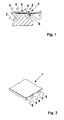
- a vehicle lamp has a housing with a rear wall 1, an optical one System 2 and an electronic carrier 3.
- a light-emitting element (not shown) is located on the carrier 3.
- the carrier 3, and thus also the light-emitting element, is with the optical system 2 firmly connected, or at least with this in one fixed reference, for example by a predetermined fixed adjustment of this Components to each other.
- the rear wall 1 has arches 4, 4 'and webs 5, 5', 5 ".
- the webs 5, 5 ', 5 " serve as stabilizers for the rear wall 1.
- the carrier 3 has cutouts 6 on, in which the webs 5 engage so that the arches 4 rest on the carrier 3.
- the webs 5 ' oriented towards the outside.
- the wall material and the wall thickness of the bulges shown in FIGS. 1 + 3 4 is chosen so that the arches 4 formed from it itself a certain one Have elasticity and thereby build up a spring effect.
- the embodiment shown in FIG. 4 is the webs 5 "with struts 7 connected, which are applied to a thin film 8.
- the Struts 7 elastic properties and are bent such that form the bulges 4 'between the webs 5' as a spring.
- the housing rear wall 1 is connected to the housing by suitable connecting means, for example, a detent connected. Basically, the housing can the housing rear wall 1 can also be made in one piece.
- the carrier 3 is together connected to the optical system with the housing and so in it fitted that in the "cold" state, the rear wall 1 with a predetermined mechanical tension is present on the carrier.
- the barrel-shaped arches 4, 4 ' act as a spring with a spring force acting in the direction 9, so that a non-positive connection between the bulges 4, 4 'and the Carrier 3 is built.
- the carrier 3 is based on the optical system 2, so that bending is prevented.
- the support also be carried out by appropriately arranged supporting elements.
- the individual components of the housing heat up in luminaire operation vary in strength and stretch due to this warming and their different coefficients of thermal expansion.
- the carrier 3 takes the light emitting by the luminaire function Elements generated waste heat.
- the positive connection to the The rear wall of the housing 1 now acts as a thermal contact that transfers the waste heat Dissipates heat conduction through the rear wall 1 to the outside.
- the increased spring force will taken up by the housing. Since the housing rear wall 1 to the carrier 3rd Can perform relative movements, thermal stresses between avoided these components.
- the non-positive connection remains regardless of the degree of heating, the thermal contact between the rear wall of the housing 1 and carrier 3 received.
Landscapes
- Engineering & Computer Science (AREA)
- General Engineering & Computer Science (AREA)
- Physics & Mathematics (AREA)
- Microelectronics & Electronic Packaging (AREA)
- Optics & Photonics (AREA)
- Mechanical Engineering (AREA)
- Arrangement Of Elements, Cooling, Sealing, Or The Like Of Lighting Devices (AREA)
Abstract
Description
- Figur 1:
- Eine schematische Darstellung einer Gehäuserückwand einer Fahrzeugleuchte mit einem elektronischen Träger und einem optischen System von der Seite im Schnitt,
- Figur 2:
- eine perspektivische Draufsicht der Gehäuserückwand,
- Figur 3
- eine zweite Ausführungsform der Gehäuserückwand,
- Figur 4
- eine dritte Ausführungsform der Gehäuserückwand und
- Figur 5
- eine perspektivische Draufsicht der Gehäuserückwand von Fig. 4.
Claims (10)
- Fahrzeugleuchte mit einem Gehäuse, einem zwischen einer Gehäuserückwand und einem optischen System angeordneten elektronischen Träger, auf dem mindestens ein wärmeerzeugendes lichtemittierendes Bauteil elektrisch verschaltet ist, das zu dem optischen System in einem festen Bezug steht, dadurch gekennzeichnet, dass die Gehäuserückwand (1) mindestens eine als Feder wirkende tonnenförmige Wölbung (4, 4') aufweist, die kraftschlüssig auf dem Träger (3) aufliegt, so dass die Wölbung (4, 4') mit dem Träger (3) in thermischem Kontakt steht und die Gehäuserückwand (1) bezüglich des Trägers (3) beweglich ist.
- Fahrzeugleuchte nach Anspruch 1, dadurch gekennzeichnet, dass zwischen den Wölbungen (4) der Gehäuserückwand (1) nach innen zeigende, dem Träger (3) zugewandte Stege (5) angeordnet sind.
- Fahrzeugleuchte nach Anspruch 1 und 2, dadurch gekennzeichnet, dass der Träger (3) Aussparungen (6) aufweist, in die die nach innen zeigenden Stege (5) eingreifen.
- Fahrzeugleuchte nach einem der Ansprüche 1 bis 3, dadurch gekennzeichnet, dass zwischen den Wölbungen (4, 4') der Gehäuserückwand (1) nach außen zeigende, dem Träger (3) abgewandte Stege (5', 5") angeordnet sind.
- Fahrzeugleuchte nach einem der Ansprüche 1 bis 4, dadurch gekennzeichnet, dass die Wölbungen (4') durch, die Stege (5") verbindende gebogene Verstrebungen (7) ausgebildet sind, die formschlüssig auf einer Folie (8) aufgebracht sind.
- Fahrzeugleuchte nach einem der Ansprüche 1 bis 5, dadurch gekennzeichnet, dass die Wölbungen (4, 4') aus einem Gehäusematerial ausgebildet sind.
- Fahrzeugleuchte nach einem der Ansprüche 1 bis 6, dadurch gekennzeichnet, dass die Wölbungen (4, 4') aus einem Metall ausgebildet sind.
- Fahrzeugleuchte nach einem der Ansprüche 1 bis 7, dadurch gekennzeichnet, dass die Wölbungen (4) in einer Verbundbauweise bestehend aus mindestens zwei Schichten ausgebildet sind.
- Fahrzeugleuchte nach einem der Ansprüche 1 bis 8, dadurch gekennzeichnet, dass die Wölbungen (4, 4') einen elektrischen Kontakt zu dem Träger (3) aufweisen.
- Fahrzeugleuchte nach einem der Ansprüche 1 bis 8, dadurch gekennzeichnet, dass die Wölbungen (4, 4') auf der dem Träger (3) zugewandten Seite eine elektrische Isolierschicht aufweisen.
Applications Claiming Priority (2)
| Application Number | Priority Date | Filing Date | Title |
|---|---|---|---|
| DE10139252 | 2001-08-09 | ||
| DE10139252A DE10139252A1 (de) | 2001-08-09 | 2001-08-09 | Fahrzeugleuchte |
Publications (2)
| Publication Number | Publication Date |
|---|---|
| EP1286107A2 true EP1286107A2 (de) | 2003-02-26 |
| EP1286107A3 EP1286107A3 (de) | 2006-04-26 |
Family
ID=7694982
Family Applications (1)
| Application Number | Title | Priority Date | Filing Date |
|---|---|---|---|
| EP02016043A Withdrawn EP1286107A3 (de) | 2001-08-09 | 2002-07-19 | Fahrzeugleuchte |
Country Status (2)
| Country | Link |
|---|---|
| EP (1) | EP1286107A3 (de) |
| DE (1) | DE10139252A1 (de) |
Families Citing this family (1)
| Publication number | Priority date | Publication date | Assignee | Title |
|---|---|---|---|---|
| DE102009039870A1 (de) * | 2009-09-03 | 2011-03-10 | Hella Kgaa Hueck & Co. | Beleuchtungsvorrichtung für Fahrzeuge |
Family Cites Families (2)
| Publication number | Priority date | Publication date | Assignee | Title |
|---|---|---|---|---|
| US5934798A (en) * | 1997-03-07 | 1999-08-10 | Truck-Lite Co., Inc. | Light emitting diode license lamp |
| DE19837553A1 (de) * | 1998-08-19 | 2000-02-24 | Hella Kg Hueck & Co | Fahrzeugleuchte |
-
2001
- 2001-08-09 DE DE10139252A patent/DE10139252A1/de not_active Withdrawn
-
2002
- 2002-07-19 EP EP02016043A patent/EP1286107A3/de not_active Withdrawn
Non-Patent Citations (1)
| Title |
|---|
| None * |
Also Published As
| Publication number | Publication date |
|---|---|
| EP1286107A3 (de) | 2006-04-26 |
| DE10139252A1 (de) | 2003-02-20 |
Similar Documents
| Publication | Publication Date | Title |
|---|---|---|
| EP2521876B1 (de) | Led-leuchtvorrichtung und verfahren zum herstellen einer led-leuchtvorrichtung | |
| DE19909399C1 (de) | Flexibles LED-Mehrfachmodul, insb. für ein Leuchtengehäuse eines Kraftfahrzeuges | |
| DE10110835B4 (de) | Beleuchtungsanordnung mit einer Mehrzahl von LED-Modulen auf einer Kühlkörperoberfläche | |
| EP1719189B1 (de) | Leuchtdioden-anordnung für eine hochleistungs-leuchtdiode und verfahren zur herstellung einer leuchtdioden-anordnung | |
| DE102007023918A1 (de) | Beleuchtungseinheit | |
| DE102007057533A1 (de) | Kühlkörper und Verfahren zur Herstellung eines Kühlkörpers | |
| DE10324909A1 (de) | Gehäuse für ein strahlungsemittierendes Bauelement, Verfahren zu dessen Herstellung und strahlungsemittierendes Bauelement | |
| DE102017131063A1 (de) | LED-Modul mit einem stabilisierten Leadframe | |
| DE102006001711B4 (de) | Beleuchtungseinrichtung für ein Kraftfahrzeug | |
| DE202018105898U1 (de) | Beleuchtungsvorrichtung mit Leadframe | |
| EP2622259A1 (de) | Leuchtmodulanordnung mit einer led auf einer platine | |
| DE202007012096U1 (de) | Elektrische Anschlußvorrichtung für leitende Kontakte, insbesondere Messerkontakte | |
| DE10234995A1 (de) | Leuchtdiodenanordnung mit thermischem Chipanschluß und Leuchtdiodenmodul | |
| EP2141406A2 (de) | Leuchte | |
| DE20120770U1 (de) | Oberflächenmontierte LED-Mehrfachanordnung und Beleuchtungseinrichtung damit | |
| DE102023111892A1 (de) | Led-leuchte für ein fahrzeug und verfahren zu ihrer herstellung unter verwendung von mid- und magnetinduktions-technologien | |
| DE102004001124B3 (de) | Leuchte, insbesondere Warnleuchte, für ein Fahrzeug | |
| DE202006017583U1 (de) | Beleuchtungsvorrichtung | |
| EP2171352B1 (de) | Leuchtmittel | |
| EP1552983A1 (de) | Leuchte, insbesondere Warnleuchte, für ein Fahrzeug | |
| DE10331532B4 (de) | Beleuchtungsvorrichtung | |
| DE10139252A1 (de) | Fahrzeugleuchte | |
| DE102008030353B4 (de) | Fahrzeugleuchte mit einem Wärme leitenden Kunststoff | |
| EP2273182B1 (de) | Dreidimensionales LED-Trägerelement mit thermischer Leitfähigkeit | |
| DE102014107217A1 (de) | Leistungshalbleitermodul |
Legal Events
| Date | Code | Title | Description |
|---|---|---|---|
| PUAI | Public reference made under article 153(3) epc to a published international application that has entered the european phase |
Free format text: ORIGINAL CODE: 0009012 |
|
| AK | Designated contracting states |
Kind code of ref document: A2 Designated state(s): AT BE BG CH CY CZ DE DK EE ES FI FR GB GR IE IT LI LU MC NL PT SE SK TR Designated state(s): AT BE BG CH CY CZ DE DK EE ES FI FR GB GR IE IT LI LU MC NL PT SE SK TR |
|
| AX | Request for extension of the european patent |
Extension state: AL LT LV MK RO SI |
|
| RAP1 | Party data changed (applicant data changed or rights of an application transferred) |
Owner name: HELLA KGAA HUECK & CO. |
|
| PUAL | Search report despatched |
Free format text: ORIGINAL CODE: 0009013 |
|
| AK | Designated contracting states |
Kind code of ref document: A3 Designated state(s): AT BE BG CH CY CZ DE DK EE ES FI FR GB GR IE IT LI LU MC NL PT SE SK TR |
|
| AX | Request for extension of the european patent |
Extension state: AL LT LV MK RO SI |
|
| 17P | Request for examination filed |
Effective date: 20061018 |
|
| GRAP | Despatch of communication of intention to grant a patent |
Free format text: ORIGINAL CODE: EPIDOSNIGR1 |
|
| AKX | Designation fees paid |
Designated state(s): AT BE BG CH CY CZ DE DK EE ES FI FR GB GR IE IT LI LU MC NL PT SE SK TR |
|
| STAA | Information on the status of an ep patent application or granted ep patent |
Free format text: STATUS: THE APPLICATION IS DEEMED TO BE WITHDRAWN |
|
| 18D | Application deemed to be withdrawn |
Effective date: 20070418 |