EP1285986A1 - Washing machine of improved type - Google Patents
Washing machine of improved type Download PDFInfo
- Publication number
- EP1285986A1 EP1285986A1 EP01830538A EP01830538A EP1285986A1 EP 1285986 A1 EP1285986 A1 EP 1285986A1 EP 01830538 A EP01830538 A EP 01830538A EP 01830538 A EP01830538 A EP 01830538A EP 1285986 A1 EP1285986 A1 EP 1285986A1
- Authority
- EP
- European Patent Office
- Prior art keywords
- reservoir
- tub
- washing machine
- machine according
- liquid
- Prior art date
- Legal status (The legal status is an assumption and is not a legal conclusion. Google has not performed a legal analysis and makes no representation as to the accuracy of the status listed.)
- Granted
Links
- 238000005406 washing Methods 0.000 title claims abstract description 49
- 239000007788 liquid Substances 0.000 claims abstract description 22
- 238000005086 pumping Methods 0.000 claims abstract 6
- XLYOFNOQVPJJNP-UHFFFAOYSA-N water Substances O XLYOFNOQVPJJNP-UHFFFAOYSA-N 0.000 claims description 49
- 238000010438 heat treatment Methods 0.000 claims description 3
- 239000003599 detergent Substances 0.000 description 10
- 238000011084 recovery Methods 0.000 description 9
- 238000004064 recycling Methods 0.000 description 7
- 239000013505 freshwater Substances 0.000 description 6
- 239000000654 additive Substances 0.000 description 5
- 208000012886 Vertigo Diseases 0.000 description 3
- 230000010355 oscillation Effects 0.000 description 3
- 238000009428 plumbing Methods 0.000 description 3
- 238000009987 spinning Methods 0.000 description 3
- 230000005540 biological transmission Effects 0.000 description 2
- 238000005452 bending Methods 0.000 description 1
- 238000000071 blow moulding Methods 0.000 description 1
- 230000003247 decreasing effect Effects 0.000 description 1
- 238000001035 drying Methods 0.000 description 1
- 238000001914 filtration Methods 0.000 description 1
- 239000012530 fluid Substances 0.000 description 1
- 230000003993 interaction Effects 0.000 description 1
- 238000000465 moulding Methods 0.000 description 1
- 230000003534 oscillatory effect Effects 0.000 description 1
- 239000008237 rinsing water Substances 0.000 description 1
- 238000007789 sealing Methods 0.000 description 1
- 229920002994 synthetic fiber Polymers 0.000 description 1
Images


Classifications
-
- D—TEXTILES; PAPER
- D06—TREATMENT OF TEXTILES OR THE LIKE; LAUNDERING; FLEXIBLE MATERIALS NOT OTHERWISE PROVIDED FOR
- D06F—LAUNDERING, DRYING, IRONING, PRESSING OR FOLDING TEXTILE ARTICLES
- D06F37/00—Details specific to washing machines covered by groups D06F21/00 - D06F25/00
- D06F37/20—Mountings, e.g. resilient mountings, for the rotary receptacle, motor, tub or casing; Preventing or damping vibrations
-
- D—TEXTILES; PAPER
- D06—TREATMENT OF TEXTILES OR THE LIKE; LAUNDERING; FLEXIBLE MATERIALS NOT OTHERWISE PROVIDED FOR
- D06F—LAUNDERING, DRYING, IRONING, PRESSING OR FOLDING TEXTILE ARTICLES
- D06F39/00—Details of washing machines not specific to a single type of machines covered by groups D06F9/00 - D06F27/00
- D06F39/20—Arrangements for water recovery
Definitions
- the present invention relates to a washing machine or washer-drier, of the type comprising a recovery reservoir for the washing water.
- the object of this invention is to provide a washing machine which, while having a relatively low weight, provides excellent characteristics of stability and balancing during operation.
- the washing machine according to the present invention has a relatively low weight, when not in operation, enabling it to be transported more easily.
- the novel arrangement of the elements of the machine provides an additional advantage, in that the user is able to load garments and linen into the tub unit and remove them from it without excessive bending, since the tub unit is in a relatively higher position in this machine.
- the novel arrangement of the elements of the machine also makes it possible to recover the heat in the environment and that developed during operation, in order to preheat the water which is used, thus providing a corresponding saving in energy.
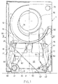
- FIGs 1 to 3 show a first embodiment of a washing machine according to the present invention.
- This washing machine is provided with an outer box-shaped casing 1.
- a tub unit 10 which houses a spinning drum 12, mounted rotatably on the rear portion of the tub unit 10, and is connected with the exterior of the casing 1 by a closable hatch 15, the closing of which is made watertight by a sealing gasket 16 (shown in Figure 2).
- the tub unit 10 is supported in an oscillatory way by dampers 17 connected in a known way to the casing 1.
- a plurality of counterweights 19 is suspended on the lower portion of the tub unit 10, in such a way as to balance the tub unit 10 during operation.
- An electric motor 20 is also fixed to the lower portion of the tub unit 10, in a median position with respect to the width of the unit, and is interposed between two counterweights 19 placed symmetrically about the vertical plane containing the principal axis of the drum 12.
- the motor 20 can cause the drum 12 to rotate in a known way, by transmission means 21 (shown in Figure 2), of the belt type for example.
- the washing machine comprises, within the casing 1, a pair of water reservoirs 31 and 32, whose function is described below, positioned below the tub unit 10.
- a mains water reservoir 31, having a smaller capacity is mounted on the base of the casing 1, while a recovered water reservoir 32, having a greater capacity, is fixed to the upper surface of the reservoir 31.
- the reservoirs 31 and 32 are preferably made from synthetic material, for example plastic, and are produced, for example, by moulding or blow moulding, and welded to each other in such a way that there is a separating surface 33 which prevents a direct flow of water between the reservoirs 31 and 32.
- the two reservoirs 31 and 32 are made and joined together in such a way that the heat exchange surfaces are as large as possible.
- Housings are formed near the lateral edges of the surface 33 for a first and a second electrically powered pump 41 and 42.
- Each pump unit 41 and 42 whose operation is described below, comprises a double pump, having two coaxial pump sections, and a water filter capable of completely filtering the solution which is treated.
- FIGS 1 and 2 show the arrangement of the hydraulic circuit of the reservoir 31 of the washing machine according to the present invention.
- the reservoir 31 is connected to the external water mains via a solenoid-operated filling valve 51 ( Figure 2), which permits the selective admission of water to the lower reservoir 31.
- the lower reservoir 31 is also connected, through an aperture 52, to a water supply tube 53, which runs up the rear portion of the casing 1 to a detergent filling holder 54 (shown in greater detail in figures 7 and 8), in which the water can be mixed selectively with the detergent and/or various additives, in a conventional way.
- the water is discharged by a tube (shown in Figures 7 and 8) into the tub unit 10. It is also possible for the water to reach the tub unit 10 after bypassing, in a known way, the compartments containing detergent or additives of the holder 54.
- a further detergent holder 54bis ( Figure 2) is inserted in the closable porthole hatch 15. This holder is connected for operation to recycling pipes 59. This additional holder 54bis enables further detergent to be added during recycling. The additional holder 54bis also completes the ideal profile of the porthole hatch.
- a base portion 55 of the tub unit 10 is connected to an outlet tube 56, which extends downwards to the first pump unit 41.
- the pump unit 41 which is essentially identical to a conventional drainage pump, is designed in such a way that it can selectively pump the liquid, by means of one or other section of the double pump, along a recycling tube 57 or along a discharge tube 58, both connected to the said pump unit.
- the recycling tube 57 extends upwards along the rear portion of the casing 1, and is then connected to the tub unit 10 through a pipe 59 located near the hatch 15.
- the pipe 59 supplies the additional holder 54bis described above.
- the discharge tube 58 extends along the rear portion of the casing 1 to the external drainage network.
- FIGS 1 and 3 show the arrangement of the hydraulic circuit of the upper reservoir 32 of the washing machine according to the present invention.
- the reservoir 32 is connected to the pump unit 42, which is designed in such a way that it can draw the liquid from this reservoir, by means of a first section of the double pump, and pump it along a delivery siphon 61 to the tub, this siphon extending upwards along one side of the casing 1, reaching a point above the filling level of the liquid in the tub unit (10).
- the tube 61 is then connected to the tub unit 10 through an aperture 62.
- the base portion 55 of the tub unit 10 is connected to a recovery tube 63, which extends downwards to the second pump unit 42.
- the pump unit 42 is designed to be able to pump the liquid, by means of a second section of the double pump, along a delivery siphon 64 to the upper reservoir, this siphon extending upwards along the rear portion of the casing 1, reaching a point above the filling level of the liquid in the tub unit 10, and closing the recovery circuit.
- the operation of the washing machine according to the present invention is controlled conventionally by an electronic control unit, indicated schematically by the number 70, which can be used to set different programs according to the different washing conditions.
- the control unit opens the solenoid valve 51, allowing the external mains water to fill the lower reservoir 31, the supply tube 53, and also, partially, the tub unit 10.
- the tub unit 10 can be filled partially, to a predetermined level, after the recovery reservoir 32 has been filled through the recovery tube 63, the pump unit 42, and the tube 64 for delivery to the reservoir.
- the reaching of the predetermined level of fluid in the tub 10 can be programmed by means of the entry of water through the reservoir 31, or also through the reservoir 32 for recovering the quantity of water which has been stored in advance.
- some water is always present in the reservoirs 31 and 32 during the spinning operations, which require high rotation speeds of the washing drum.
- the control unit operates to divert the flow of water, by preventing its flow through the compartments of the holder 54 containing detergent and/or additives, in such a way that the water reaching the reservoir 32 is essentially pure; when the reservoir 32 has been filled, on the other hand, the water is introduced into the tub unit 10 after being made to pass through the compartments of the holder 54 containing detergent and any necessary additives.
- Conventional heating means heat the water flowing into the tub unit 10 to a predetermined temperature; some of this heated water flows into the upper reservoir 32. The heat is then partially transmitted from the reservoir 32, through the separating surface 33, to the fresh water present in the reservoir 31, thus pre-heating it for any requisite further use during operation.
- the washing liquid flowing out of the tub unit 10 through the outlet tube 56 is made to recirculate through the recycling tube 57, and is then reintroduced into the tub unit 10, thus increasing the washing efficiency.
- liquid delivered from the pump unit 41 is sent, not into the recycling tube 57, but into the discharge tube 58 to discharge the dirty liquid to the exterior, until the tub unit 10 is emptied.
- a first section of the pump unit 42 delivers the water from the reservoir 32 along the tub delivery siphon 61 into the tub unit 10.
- the water present in the reservoir 32 forms an additional balance weight for the washing machine which is required to stabilize the structure during operation, and especially during the spinning stage.
- the pump unit 41 is turned on to discharge the water to the exterior through the discharge tube 58, until the tub unit 10 is emptied, and the reservoir 32 is also emptied by interaction with the pump unit 42. It is also possible to specify a case in which the recovery of clean water, for example the water from the final rinse, is specifically carried out in advance, so that it can be stored in the recovery reservoir.
- the presence of the weight of water in the reservoirs 32 during the operation of the machine provides the necessary stability and advantageously enables the weight of the counterweights 19 to be reduced by comparison with conventional solutions.
- any water present in the reservoir 31 is heated naturally to the ambient temperature. Consequently, the fact that water remains in the reservoir 31 enables the ambient temperature to be utilized, providing a saving of approximately 8°C for example.
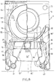
- FIGS 3 to 6 show a second embodiment of a washing machine according to the present invention.
- the elements corresponding to those of Figures 1 to 3 are indicated with the same numerical references, while those which are different are indicated with an apostrophe.
- the arrangement of the components and the plumbing connections are essentially similar to those of the first embodiment, except for the pair of water reservoirs located under the tub unit 10.
- a mains water reservoir 31' having a smaller capacity, is made integral with the tub unit 10, being fixed to the bases of the counterweights 19, while a recovered water reservoir 32', having a greater capacity, is fixed to the lower surface of the reservoir 31'.
- the reservoir 31' Since it is now in a significantly higher position and above the reservoir 32', the reservoir 31' is not in this case connected to the solenoid-operated filling valve 51 directly, but is connected through a filling tube 52'.
- the functions of the reservoirs 31' and 32' are essentially the same, and in particular the heat exchange between them takes place through a separating surface 33'.
- the motor 20 is in this case essentially in contact with the upper reservoir 31', enabling the heat dissipated by this motor to be recovered during operation to additionally pre-heat the fresh water in the reservoir 31', thus providing an additional relative saving in energy.
- a plurality of fins 81' can be placed on the contact surface between the motor 20 and the upper reservoir 31'. These fins, being immersed in the water in the reservoir 31, improve the transmission of heat from the motor 20 to the upper reservoir 31'.
- the reservoirs 31' and 32' are fixed directly to the tub unit 10, it is possible to provide directly for the containment of the oscillations of this unit, which can be improved by making these reservoirs in a shape which takes into account the distribution of the loads during the oscillations of the tub unit 10.
- the weight of the counterweights 19 can be further decreased by 50% with respect to conventional machines.
- FIG. 7 shows a third embodiment of a washing machine according to the present invention.
- the elements corresponding to those of Figures 1 to 6 are indicated with the same numerical references, while those which are different are indicated with a double apostrophe.
- a single reservoir 32'' is made integral with the tub unit 10, being fixed to the bases of the counterweights 19.
- the fresh water enters the washing machine through the solenoid-operated filling valve 51, which in this case is located in the upper portion of the casing 1, and flows directly into the detergent holder 54. Passing through this holder, the water is sent into the tub unit 10.
- the arrangement of the remaining components and the plumbing connections are essentially similar to those of the second embodiment, except for a recycling tube 57'', which, as in the first two embodiments, departs from the pump unit 41, but terminates in the detergent holder 54.
- the recycled water can be additionally mixed with the detergent during the washing stage.
- there is a pipe which connects the reservoir 32'' directly to the tub unit 10, to act as an overflow device.
- the single reservoir 32'' essentially has the same functions as those of the separate reservoirs 31' and 32', but cannot be used to pre-heat the supplied fresh water, since it is not connected directly to the exterior. However, this single reservoir can be used to pre-heat the water which is subsequently recovered and stored in it.
- a connection of this type is provided in a fourth embodiment, shown in Fig. 8.
- the elements corresponding to those of Figures 1 to 7 are indicated with the same numerical references, while those which are different are indicated with a triple apostrophe.
- the arrangement of the components and the plumbing connections are essentially identical to those of the third embodiment, but the direct connection between the solenoid-operated filling valve 51 and the reservoir 32'' is formed by means of a bypass tube 91'''.
- the fresh water entering through the solenoid-operated valve 51 can be diverted so that it passes directly into the reservoir 32'' instead of into the holder 54. This diversion is carried out with known means, operated by the control unit 70.
- fresh water is pre-heated in the reservoir 32'', by mixing with the hot water which is already present in it.
- the control unit can then add water at ambient temperature to the water stored in the reservoir 32''.
Landscapes
- Engineering & Computer Science (AREA)
- Textile Engineering (AREA)
- Detail Structures Of Washing Machines And Dryers (AREA)
Abstract
Description
- The present invention relates to a washing machine or washer-drier, of the type comprising a recovery reservoir for the washing water.
- An example of a washing machine of this type is described in EP 0 607 628, in which a reservoir is provided for the recovery of the washing water, and particularly of the rinsing water, for the re-use of the water during subsequent washing. In this document, the reservoir is located, in the conventional way, in the upper part of the machine.
- To overcome the problems of balancing which can affect a machine of this type during its operation, it is necessary to provide one or more counterweights which create a large weight capable of opposing the oscillations caused by the rotation of the drum, especially during spin-drying.
- A weight of this kind considerably increases the weight of the machine and therefore gives rise to problems of transport.
- The object of this invention is to provide a washing machine which, while having a relatively low weight, provides excellent characteristics of stability and balancing during operation.
- According to the invention, this object is achieved with a washing machine having the characteristics defined in the claims.
- With a machine designed in this way, it is possible to decrease the fixed balance weights, by using the water present in the reservoir during operation as an additional weight. Thus the washing machine according to the present invention has a relatively low weight, when not in operation, enabling it to be transported more easily.
- Moreover, the novel arrangement of the elements of the machine provides an additional advantage, in that the user is able to load garments and linen into the tub unit and remove them from it without excessive bending, since the tub unit is in a relatively higher position in this machine.
- The novel arrangement of the elements of the machine also makes it possible to recover the heat in the environment and that developed during operation, in order to preheat the water which is used, thus providing a corresponding saving in energy.
- The characteristics and advantages of the present invention are made clear by the following detailed description, provided purely by way of example and without restrictive intent, with reference to the attached drawings, in which:
- Figure 1 is a schematic and partially sectional front view of a first embodiment of washing machine according to the present invention;
- Figure 2 is a schematic and partially sectional side view, in the direction of the arrow II, of the washing machine of Figure 1;
- Figure 2 is a schematic and partially sectional side view of a washing machine with an inclined drum;
- Figure 3 is a schematic and partially sectional side view, in the direction of the arrow III, of a portion of the washing machine of Figure 1;
- Figure 4 is a schematic and partially sectional front view of a second embodiment of a washing machine according to the present invention;
- Figure 5 is a schematic and partially sectional side view, in the direction of the arrow V, of the washing machine of Figure 4;
- Figure 6 is a schematic and partially sectional side view, in the direction of the arrow VI, of a portion of the washing machine of Figure 1;
- Figure 7 is a schematic and partially sectional front view of a third embodiment of a washing machine according to the present invention; and
- Figure 8 is a schematic and partial sectional front view of a fourth embodiment of a washing machine according to the present invention.
- Figures 1 to 3 show a first embodiment of a washing machine according to the present invention. This washing machine is provided with an outer box-shaped casing 1. Within the upper portion of the casing 1 there is located a
tub unit 10, which houses a spinningdrum 12, mounted rotatably on the rear portion of thetub unit 10, and is connected with the exterior of the casing 1 by aclosable hatch 15, the closing of which is made watertight by a sealing gasket 16 (shown in Figure 2). Thetub unit 10 is supported in an oscillatory way bydampers 17 connected in a known way to the casing 1. - A plurality of
counterweights 19 is suspended on the lower portion of thetub unit 10, in such a way as to balance thetub unit 10 during operation. Anelectric motor 20 is also fixed to the lower portion of thetub unit 10, in a median position with respect to the width of the unit, and is interposed between twocounterweights 19 placed symmetrically about the vertical plane containing the principal axis of thedrum 12. Themotor 20 can cause thedrum 12 to rotate in a known way, by transmission means 21 (shown in Figure 2), of the belt type for example. - The washing machine according to the present embodiment of the invention comprises, within the casing 1, a pair of
water reservoirs tub unit 10. Amains water reservoir 31, having a smaller capacity, is mounted on the base of the casing 1, while a recoveredwater reservoir 32, having a greater capacity, is fixed to the upper surface of thereservoir 31. Thereservoirs surface 33 which prevents a direct flow of water between thereservoirs reservoirs - Housings are formed near the lateral edges of the
surface 33 for a first and a second electrically poweredpump pump unit - Figures 1 and 2 show the arrangement of the hydraulic circuit of the
reservoir 31 of the washing machine according to the present invention. In these and in the following figures, the direction of flow of liquids is indicated by arrows inside the pipes. Thereservoir 31 is connected to the external water mains via a solenoid-operated filling valve 51 (Figure 2), which permits the selective admission of water to thelower reservoir 31. Thelower reservoir 31 is also connected, through anaperture 52, to awater supply tube 53, which runs up the rear portion of the casing 1 to a detergent filling holder 54 (shown in greater detail in figures 7 and 8), in which the water can be mixed selectively with the detergent and/or various additives, in a conventional way. From here, the water is discharged by a tube (shown in Figures 7 and 8) into thetub unit 10. It is also possible for the water to reach thetub unit 10 after bypassing, in a known way, the compartments containing detergent or additives of theholder 54. - In one particular embodiment, a further detergent holder 54bis (Figure 2) is inserted in the
closable porthole hatch 15. This holder is connected for operation to recyclingpipes 59. This additional holder 54bis enables further detergent to be added during recycling. The additional holder 54bis also completes the ideal profile of the porthole hatch. - A
base portion 55 of thetub unit 10 is connected to anoutlet tube 56, which extends downwards to thefirst pump unit 41. Thepump unit 41, which is essentially identical to a conventional drainage pump, is designed in such a way that it can selectively pump the liquid, by means of one or other section of the double pump, along arecycling tube 57 or along adischarge tube 58, both connected to the said pump unit. Therecycling tube 57 extends upwards along the rear portion of the casing 1, and is then connected to thetub unit 10 through apipe 59 located near thehatch 15. In a different embodiment, thepipe 59 supplies the additional holder 54bis described above. Thedischarge tube 58, on the other hand, extends along the rear portion of the casing 1 to the external drainage network. - Figures 1 and 3 show the arrangement of the hydraulic circuit of the
upper reservoir 32 of the washing machine according to the present invention. Thereservoir 32 is connected to thepump unit 42, which is designed in such a way that it can draw the liquid from this reservoir, by means of a first section of the double pump, and pump it along adelivery siphon 61 to the tub, this siphon extending upwards along one side of the casing 1, reaching a point above the filling level of the liquid in the tub unit (10). Thetube 61 is then connected to thetub unit 10 through anaperture 62. Thebase portion 55 of thetub unit 10 is connected to arecovery tube 63, which extends downwards to thesecond pump unit 42. Thepump unit 42 is designed to be able to pump the liquid, by means of a second section of the double pump, along adelivery siphon 64 to the upper reservoir, this siphon extending upwards along the rear portion of the casing 1, reaching a point above the filling level of the liquid in thetub unit 10, and closing the recovery circuit. - The operation of the washing machine according to the present invention is controlled conventionally by an electronic control unit, indicated schematically by the
number 70, which can be used to set different programs according to the different washing conditions. - The control unit opens the
solenoid valve 51, allowing the external mains water to fill thelower reservoir 31, thesupply tube 53, and also, partially, thetub unit 10. Thetub unit 10 can be filled partially, to a predetermined level, after therecovery reservoir 32 has been filled through therecovery tube 63, thepump unit 42, and thetube 64 for delivery to the reservoir. - The reaching of the predetermined level of fluid in the
tub 10 can be programmed by means of the entry of water through thereservoir 31, or also through thereservoir 32 for recovering the quantity of water which has been stored in advance. However, some water is always present in thereservoirs - In the stages in which the
reservoir 32 is filled, the control unit operates to divert the flow of water, by preventing its flow through the compartments of theholder 54 containing detergent and/or additives, in such a way that the water reaching thereservoir 32 is essentially pure; when thereservoir 32 has been filled, on the other hand, the water is introduced into thetub unit 10 after being made to pass through the compartments of theholder 54 containing detergent and any necessary additives. - Conventional heating means (not illustrated), of the resistance type for example, heat the water flowing into the
tub unit 10 to a predetermined temperature; some of this heated water flows into theupper reservoir 32. The heat is then partially transmitted from thereservoir 32, through theseparating surface 33, to the fresh water present in thereservoir 31, thus pre-heating it for any requisite further use during operation. - During the washing stage, the washing liquid flowing out of the
tub unit 10 through theoutlet tube 56 is made to recirculate through therecycling tube 57, and is then reintroduced into thetub unit 10, thus increasing the washing efficiency. - At the end of the washing stage, liquid delivered from the
pump unit 41 is sent, not into therecycling tube 57, but into thedischarge tube 58 to discharge the dirty liquid to the exterior, until thetub unit 10 is emptied. - This is followed by further stages, for example a further filling of the
tub unit 10 with water mixed with predetermined additives, after which one or more rinsing stages start. - During rinsing, a first section of the
pump unit 42 delivers the water from thereservoir 32 along the tub delivery siphon 61 into thetub unit 10. The water leaves thebase portion 55 through therecovery tube 63, is returned by the second section of thepump unit 42 and forced back into thereservoir 32 through the siphon 64; thus the water level in thereservoir 32 is kept essentially constant. The water present in thereservoir 32 forms an additional balance weight for the washing machine which is required to stabilize the structure during operation, and especially during the spinning stage. - Finally, the
pump unit 41 is turned on to discharge the water to the exterior through thedischarge tube 58, until thetub unit 10 is emptied, and thereservoir 32 is also emptied by interaction with thepump unit 42. It is also possible to specify a case in which the recovery of clean water, for example the water from the final rinse, is specifically carried out in advance, so that it can be stored in the recovery reservoir. - Clearly, the presence of the weight of water in the
reservoirs 32 during the operation of the machine provides the necessary stability and advantageously enables the weight of thecounterweights 19 to be reduced by comparison with conventional solutions. - Moreover, any water present in the
reservoir 31 is heated naturally to the ambient temperature. Consequently, the fact that water remains in thereservoir 31 enables the ambient temperature to be utilized, providing a saving of approximately 8°C for example. - Figures 3 to 6 show a second embodiment of a washing machine according to the present invention. The elements corresponding to those of Figures 1 to 3 are indicated with the same numerical references, while those which are different are indicated with an apostrophe. The arrangement of the components and the plumbing connections are essentially similar to those of the first embodiment, except for the pair of water reservoirs located under the
tub unit 10. A mains water reservoir 31', having a smaller capacity, is made integral with thetub unit 10, being fixed to the bases of thecounterweights 19, while a recovered water reservoir 32', having a greater capacity, is fixed to the lower surface of the reservoir 31'. Since it is now in a significantly higher position and above the reservoir 32', the reservoir 31' is not in this case connected to the solenoid-operatedfilling valve 51 directly, but is connected through a filling tube 52'. The functions of the reservoirs 31' and 32' are essentially the same, and in particular the heat exchange between them takes place through a separating surface 33'. - Additionally, the
motor 20 is in this case essentially in contact with the upper reservoir 31', enabling the heat dissipated by this motor to be recovered during operation to additionally pre-heat the fresh water in the reservoir 31', thus providing an additional relative saving in energy. Advantageously, a plurality of fins 81' can be placed on the contact surface between themotor 20 and the upper reservoir 31'. These fins, being immersed in the water in thereservoir 31, improve the transmission of heat from themotor 20 to the upper reservoir 31'. - Additionally, since in this case the reservoirs 31' and 32' are fixed directly to the
tub unit 10, it is possible to provide directly for the containment of the oscillations of this unit, which can be improved by making these reservoirs in a shape which takes into account the distribution of the loads during the oscillations of thetub unit 10. Thus the weight of thecounterweights 19 can be further decreased by 50% with respect to conventional machines. - Figure 7 shows a third embodiment of a washing machine according to the present invention. The elements corresponding to those of Figures 1 to 6 are indicated with the same numerical references, while those which are different are indicated with a double apostrophe. In this embodiment, a single reservoir 32'' is made integral with the
tub unit 10, being fixed to the bases of thecounterweights 19. - The fresh water enters the washing machine through the solenoid-operated
filling valve 51, which in this case is located in the upper portion of the casing 1, and flows directly into thedetergent holder 54. Passing through this holder, the water is sent into thetub unit 10. The arrangement of the remaining components and the plumbing connections are essentially similar to those of the second embodiment, except for a recycling tube 57'', which, as in the first two embodiments, departs from thepump unit 41, but terminates in thedetergent holder 54. Thus the recycled water can be additionally mixed with the detergent during the washing stage. In one embodiment, there is a pipe which connects the reservoir 32'' directly to thetub unit 10, to act as an overflow device. - The single reservoir 32'' essentially has the same functions as those of the separate reservoirs 31' and 32', but cannot be used to pre-heat the supplied fresh water, since it is not connected directly to the exterior. However, this single reservoir can be used to pre-heat the water which is subsequently recovered and stored in it.
- A connection of this type is provided in a fourth embodiment, shown in Fig. 8. In this figure, the elements corresponding to those of Figures 1 to 7 are indicated with the same numerical references, while those which are different are indicated with a triple apostrophe. The arrangement of the components and the plumbing connections are essentially identical to those of the third embodiment, but the direct connection between the solenoid-operated
filling valve 51 and the reservoir 32'' is formed by means of a bypass tube 91'''. Thus, the fresh water entering through the solenoid-operatedvalve 51 can be diverted so that it passes directly into the reservoir 32'' instead of into theholder 54. This diversion is carried out with known means, operated by thecontrol unit 70. - Thus the fresh water is pre-heated in the reservoir 32'', by mixing with the hot water which is already present in it.
- The control unit can then add water at ambient temperature to the water stored in the reservoir 32''.
Claims (11)
- Washing machine, comprising:a tub (10) which can be filled with liquid to a specific level for washing garments;a reservoir (32; 32'; 32''), which can store rinsing liquid and is located under the tub (10); andpumping means (42) for drawing liquid from the reservoir (32, 32', 32'') and sending it to the tub (10).
- Washing machine according to Claim 1, comprising an electronic control unit (70) designed to control the operation of the pumping means (42) in such a way as to maintain a predetermined liquid level in the reservoir (32, 32', 32'') to stabilize the machine during its operation.
- Washing machine according to Claim 2, in which the electronic control unit (70) is designed to control the operation of the pumping means (42) in such a way as to keep the reservoir (32, 32', 32'') essentially full during the operation of the machine.
- Washing machine according to Claim 1, in which the reservoir (32, 32', 32'') is located in the lower part of the machine.
- Washing machine according to Claim 1, in which the reservoir (32, 32', 32'') is suspended from the tub (10).
- Washing machine according to Claim 1, comprising a second reservoir (31, 31') connected to means (51) for introducing water into the machine.
- Washing machine according to Claim 6, in which the two reservoirs (32, 32'; 31, 31') are in contact with each other to enable heat to be transmitted to the liquid contained in the second reservoir (31, 31').
- Washing machine according to Claim 6, in which the second reservoir (31, 31') is associated with heating means (81') to transmit to the water contained in it the heat generated by an electric motor (20) for driving a drum (12) contained in the tub (10).
- Washing machine according to Claim 1, in which the pumping means (42) are connected:to the tub (10) by means ofthe said pumping means (42) are also connecteda first length of tubing (61) for delivering water from the reservoir (32, 32', 32'') to the tub (10) anda second length of tubing (63) for drawing liquid out of the tub (10);to the reservoir (32, 32', 32'') througha pipe for drawing the liquid to be sent from the reservoir (32, 32', 32'') to the tub (10) anda third length of tubing (64) for introducing into the reservoir (32, 32', 32'') the liquid drawn out of the tub (10) through the second length of tubing (63).
- Washing machine according to Claim 9, in which the first length of tubing (61) is a siphon which rises to a point above the said predetermined level of the liquid in the tub (10).
- Washing machine according to Claim 9, in which the third length of tubing (64) is a siphon which rises to a point above the said predetermined level of the liquid in the tub (10).
Priority Applications (3)
| Application Number | Priority Date | Filing Date | Title |
|---|---|---|---|
| DE60104546T DE60104546T2 (en) | 2001-08-14 | 2001-08-14 | Improved washing machine |
| EP01830538A EP1285986B1 (en) | 2001-08-14 | 2001-08-14 | Washing machine of improved type |
| ES01830538T ES2223767T3 (en) | 2001-08-14 | 2001-08-14 | IMPROVED TYPE WASHING MACHINE. |
Applications Claiming Priority (1)
| Application Number | Priority Date | Filing Date | Title |
|---|---|---|---|
| EP01830538A EP1285986B1 (en) | 2001-08-14 | 2001-08-14 | Washing machine of improved type |
Publications (2)
| Publication Number | Publication Date |
|---|---|
| EP1285986A1 true EP1285986A1 (en) | 2003-02-26 |
| EP1285986B1 EP1285986B1 (en) | 2004-07-28 |
Family
ID=8184660
Family Applications (1)
| Application Number | Title | Priority Date | Filing Date |
|---|---|---|---|
| EP01830538A Expired - Lifetime EP1285986B1 (en) | 2001-08-14 | 2001-08-14 | Washing machine of improved type |
Country Status (3)
| Country | Link |
|---|---|
| EP (1) | EP1285986B1 (en) |
| DE (1) | DE60104546T2 (en) |
| ES (1) | ES2223767T3 (en) |
Cited By (7)
| Publication number | Priority date | Publication date | Assignee | Title |
|---|---|---|---|---|
| EP1710343A1 (en) * | 2005-04-04 | 2006-10-11 | Miele & Cie. KG | Front-loading laundry treatment machine like a washing and/or drying machine |
| EP1529869A3 (en) * | 2003-11-07 | 2009-01-14 | Panasonic Corporation | Drum type washing machine |
| EP2098626A1 (en) | 2008-03-03 | 2009-09-09 | Miele & Cie. KG | Frontloading washing machine |
| US20110167877A1 (en) * | 2005-11-25 | 2011-07-14 | Andrew Reason | Washing Appliance |
| IT201900005524A1 (en) * | 2019-04-10 | 2020-10-10 | J P Ind S P A | WASHING MACHINE WITH HYDRAULIC COUNTERWEIGHT SYSTEM. |
| DE102023200169A1 (en) | 2023-01-11 | 2024-07-11 | BSH Hausgeräte GmbH | Household appliance for the care of laundry items with removable weight bodies and method for changing a weight of a household appliance |
| EP4700169A1 (en) | 2024-08-21 | 2026-02-25 | BSH Hausgeräte GmbH | Household appliance for the care of laundry items |
Families Citing this family (4)
| Publication number | Priority date | Publication date | Assignee | Title |
|---|---|---|---|---|
| DE102004026735B4 (en) * | 2003-06-09 | 2009-11-19 | Lg Electronics Inc. | Drum-type mono trough washing machine and method of controlling the same |
| ES2470496B1 (en) * | 2012-12-20 | 2015-03-31 | Bsh Electrodomésticos España, S.A. | Domestic appliance with a reservoir |
| US11242645B2 (en) | 2018-11-16 | 2022-02-08 | Whirlpool Corporation | Laundry treating appliance having a door assembly |
| US11208750B2 (en) | 2018-12-29 | 2021-12-28 | Whirlpool Corporation | Laundry appliance with a deflector |
Citations (7)
| Publication number | Priority date | Publication date | Assignee | Title |
|---|---|---|---|---|
| US3078702A (en) * | 1959-05-25 | 1963-02-26 | Mc Graw Edison Co | Combination washing and drying machine |
| DE1871621U (en) * | 1963-02-23 | 1963-05-09 | Rudolf Grosse | FULLY OR SEMI-AUTOMATIC ELECTRIC WASHING MACHINE. |
| US3580014A (en) * | 1968-02-13 | 1971-05-25 | Zanussi A Spa Industrie | Machine having a rotary motion, especially washing machine, furnished with ballast |
| EP0326502A1 (en) * | 1988-01-28 | 1989-08-02 | Georges Martinez | Washing machine tub with ballast elements |
| EP0607628A1 (en) * | 1993-01-19 | 1994-07-27 | CANDY S.p.A. | A washing machine or dishwasher with liquid storage |
| EP0909848A1 (en) * | 1997-10-16 | 1999-04-21 | BSH Bosch und Siemens Hausgeräte GmbH | Household washing appliance with water tank |
| WO2000042248A1 (en) * | 1999-01-15 | 2000-07-20 | Amica Wronki S.A. | An automatic washer, especially a household washer, and a method for hydraulically ballasting a spinning basket in an automatic washer, especially household one |
-
2001
- 2001-08-14 EP EP01830538A patent/EP1285986B1/en not_active Expired - Lifetime
- 2001-08-14 DE DE60104546T patent/DE60104546T2/en not_active Expired - Lifetime
- 2001-08-14 ES ES01830538T patent/ES2223767T3/en not_active Expired - Lifetime
Patent Citations (7)
| Publication number | Priority date | Publication date | Assignee | Title |
|---|---|---|---|---|
| US3078702A (en) * | 1959-05-25 | 1963-02-26 | Mc Graw Edison Co | Combination washing and drying machine |
| DE1871621U (en) * | 1963-02-23 | 1963-05-09 | Rudolf Grosse | FULLY OR SEMI-AUTOMATIC ELECTRIC WASHING MACHINE. |
| US3580014A (en) * | 1968-02-13 | 1971-05-25 | Zanussi A Spa Industrie | Machine having a rotary motion, especially washing machine, furnished with ballast |
| EP0326502A1 (en) * | 1988-01-28 | 1989-08-02 | Georges Martinez | Washing machine tub with ballast elements |
| EP0607628A1 (en) * | 1993-01-19 | 1994-07-27 | CANDY S.p.A. | A washing machine or dishwasher with liquid storage |
| EP0909848A1 (en) * | 1997-10-16 | 1999-04-21 | BSH Bosch und Siemens Hausgeräte GmbH | Household washing appliance with water tank |
| WO2000042248A1 (en) * | 1999-01-15 | 2000-07-20 | Amica Wronki S.A. | An automatic washer, especially a household washer, and a method for hydraulically ballasting a spinning basket in an automatic washer, especially household one |
Cited By (10)
| Publication number | Priority date | Publication date | Assignee | Title |
|---|---|---|---|---|
| EP1529869A3 (en) * | 2003-11-07 | 2009-01-14 | Panasonic Corporation | Drum type washing machine |
| EP1710343A1 (en) * | 2005-04-04 | 2006-10-11 | Miele & Cie. KG | Front-loading laundry treatment machine like a washing and/or drying machine |
| US8261582B2 (en) | 2005-04-04 | 2012-09-11 | Miele & Cie. Kg | Front-loading laundry appliance such as a washing machine, a laundry dryer or a washer-dryer machine |
| US20110167877A1 (en) * | 2005-11-25 | 2011-07-14 | Andrew Reason | Washing Appliance |
| EP2098626A1 (en) | 2008-03-03 | 2009-09-09 | Miele & Cie. KG | Frontloading washing machine |
| DE102008012191A1 (en) | 2008-03-03 | 2009-09-10 | Miele & Cie. Kg | Front-loading washing machine |
| IT201900005524A1 (en) * | 2019-04-10 | 2020-10-10 | J P Ind S P A | WASHING MACHINE WITH HYDRAULIC COUNTERWEIGHT SYSTEM. |
| DE102023200169A1 (en) | 2023-01-11 | 2024-07-11 | BSH Hausgeräte GmbH | Household appliance for the care of laundry items with removable weight bodies and method for changing a weight of a household appliance |
| EP4700169A1 (en) | 2024-08-21 | 2026-02-25 | BSH Hausgeräte GmbH | Household appliance for the care of laundry items |
| DE102024207925A1 (en) | 2024-08-21 | 2026-02-26 | BSH Hausgeräte GmbH | Household appliance for the care of laundry items |
Also Published As
| Publication number | Publication date |
|---|---|
| DE60104546T2 (en) | 2005-09-15 |
| DE60104546D1 (en) | 2004-09-02 |
| EP1285986B1 (en) | 2004-07-28 |
| ES2223767T3 (en) | 2005-03-01 |
Similar Documents
| Publication | Publication Date | Title |
|---|---|---|
| AU2015224715B2 (en) | Washing machine | |
| EP1285986B1 (en) | Washing machine of improved type | |
| CN101652513B (en) | Washing machine and method of controlling the washing machine | |
| CN102191666B (en) | Washing machine | |
| CN105143543B (en) | Washing machine | |
| JP7142126B2 (en) | washing machine | |
| EP0771898B1 (en) | A washing machine with a reservoir for recovering rinsing water | |
| EP2781641B1 (en) | Washing machine with a storage tank for reusing water and method for carrying out a water reuse step | |
| EP1548173A1 (en) | Domestic washing machine and dryer which can be connected together, corresponding combined installation and corresponding process for washing and drying | |
| US20050166645A1 (en) | Washing aid dispenser and washing machine comprising said dispenser | |
| JP2020108698A (en) | Washing machine | |
| CN101341285A (en) | front load washing machine | |
| PL176584B1 (en) | Programmable washing machine | |
| CN214458942U (en) | Washing machine | |
| TW202016390A (en) | Washing machine capable of accurately determining the accuracy of the detergent, and shortening the operation time | |
| JPH0768081A (en) | Detergent loading device for washing machine | |
| CN201585389U (en) | Full-automatic production line for alkali quick-boiling, rinsing and bittern | |
| CN111411484A (en) | Washing machine | |
| CN217802641U (en) | Belt cleaning device of static mixer for resin | |
| PL188488B1 (en) | Automatic washing machine and washing liquid circulation system therefor | |
| SU1388491A1 (en) | Method and laundry machine for washing linen | |
| KR100827245B1 (en) | washer | |
| JP2001259290A (en) | Washing machine | |
| JP2023159961A (en) | washing machine | |
| KR100315486B1 (en) | Drum type washing machine |
Legal Events
| Date | Code | Title | Description |
|---|---|---|---|
| PUAI | Public reference made under article 153(3) epc to a published international application that has entered the european phase |
Free format text: ORIGINAL CODE: 0009012 |
|
| 17P | Request for examination filed |
Effective date: 20020523 |
|
| AK | Designated contracting states |
Designated state(s): AT BE CH CY DE DK ES FI FR GB GR IE IT LI LU MC NL PT SE TR Kind code of ref document: A1 Designated state(s): AT BE CH CY DE DK ES FI FR GB GR IE IT LI LU MC NL PT SE TR |
|
| AX | Request for extension of the european patent |
Extension state: AL LT LV MK RO SI |
|
| 17Q | First examination report despatched |
Effective date: 20030415 |
|
| AKX | Designation fees paid |
Designated state(s): AT BE CH CY LI |
|
| RBV | Designated contracting states (corrected) |
Designated state(s): DE ES GB IT |
|
| REG | Reference to a national code |
Ref country code: DE Ref legal event code: 8566 |
|
| GRAP | Despatch of communication of intention to grant a patent |
Free format text: ORIGINAL CODE: EPIDOSNIGR1 |
|
| GRAS | Grant fee paid |
Free format text: ORIGINAL CODE: EPIDOSNIGR3 |
|
| GRAA | (expected) grant |
Free format text: ORIGINAL CODE: 0009210 |
|
| AK | Designated contracting states |
Kind code of ref document: B1 Designated state(s): DE ES GB IT |
|
| REG | Reference to a national code |
Ref country code: GB Ref legal event code: FG4D |
|
| REG | Reference to a national code |
Ref country code: IE Ref legal event code: FG4D |
|
| REF | Corresponds to: |
Ref document number: 60104546 Country of ref document: DE Date of ref document: 20040902 Kind code of ref document: P |
|
| REG | Reference to a national code |
Ref country code: ES Ref legal event code: FG2A Ref document number: 2223767 Country of ref document: ES Kind code of ref document: T3 |
|
| REG | Reference to a national code |
Ref country code: IE Ref legal event code: MM4A |
|
| PLBE | No opposition filed within time limit |
Free format text: ORIGINAL CODE: 0009261 |
|
| STAA | Information on the status of an ep patent application or granted ep patent |
Free format text: STATUS: NO OPPOSITION FILED WITHIN TIME LIMIT |
|
| 26N | No opposition filed |
Effective date: 20050429 |
|
| PGFP | Annual fee paid to national office [announced via postgrant information from national office to epo] |
Ref country code: ES Payment date: 20130708 Year of fee payment: 13 |
|
| PGFP | Annual fee paid to national office [announced via postgrant information from national office to epo] |
Ref country code: GB Payment date: 20130821 Year of fee payment: 13 |
|
| PGFP | Annual fee paid to national office [announced via postgrant information from national office to epo] |
Ref country code: IT Payment date: 20130809 Year of fee payment: 13 |
|
| PGFP | Annual fee paid to national office [announced via postgrant information from national office to epo] |
Ref country code: DE Payment date: 20131031 Year of fee payment: 13 |
|
| REG | Reference to a national code |
Ref country code: DE Ref legal event code: R119 Ref document number: 60104546 Country of ref document: DE |
|
| GBPC | Gb: european patent ceased through non-payment of renewal fee |
Effective date: 20140814 |
|
| PG25 | Lapsed in a contracting state [announced via postgrant information from national office to epo] |
Ref country code: IT Free format text: LAPSE BECAUSE OF NON-PAYMENT OF DUE FEES Effective date: 20140814 |
|
| REG | Reference to a national code |
Ref country code: DE Ref legal event code: R119 Ref document number: 60104546 Country of ref document: DE Effective date: 20150303 |
|
| PG25 | Lapsed in a contracting state [announced via postgrant information from national office to epo] |
Ref country code: GB Free format text: LAPSE BECAUSE OF NON-PAYMENT OF DUE FEES Effective date: 20140814 Ref country code: DE Free format text: LAPSE BECAUSE OF NON-PAYMENT OF DUE FEES Effective date: 20150303 |
|
| REG | Reference to a national code |
Ref country code: ES Ref legal event code: FD2A Effective date: 20150928 |
|
| PG25 | Lapsed in a contracting state [announced via postgrant information from national office to epo] |
Ref country code: ES Free format text: LAPSE BECAUSE OF NON-PAYMENT OF DUE FEES Effective date: 20140815 |