EP1285818A1 - Hands-free device for vehicle headrest and method of use - Google Patents
Hands-free device for vehicle headrest and method of use Download PDFInfo
- Publication number
- EP1285818A1 EP1285818A1 EP02016576A EP02016576A EP1285818A1 EP 1285818 A1 EP1285818 A1 EP 1285818A1 EP 02016576 A EP02016576 A EP 02016576A EP 02016576 A EP02016576 A EP 02016576A EP 1285818 A1 EP1285818 A1 EP 1285818A1
- Authority
- EP
- European Patent Office
- Prior art keywords
- strap
- hands
- headrest
- free
- secured
- Prior art date
- Legal status (The legal status is an assumption and is not a legal conclusion. Google has not performed a legal analysis and makes no representation as to the accuracy of the status listed.)
- Granted
Links
- 238000000034 method Methods 0.000 title claims abstract description 14
- 230000013011 mating Effects 0.000 claims description 15
- 244000261422 Lysimachia clethroides Species 0.000 claims description 2
- 239000002184 metal Substances 0.000 description 6
- 238000013459 approach Methods 0.000 description 4
- 230000006870 function Effects 0.000 description 4
- 238000009434 installation Methods 0.000 description 4
- 239000000463 material Substances 0.000 description 4
- 238000002347 injection Methods 0.000 description 2
- 239000007924 injection Substances 0.000 description 2
- 238000002955 isolation Methods 0.000 description 2
- 238000004378 air conditioning Methods 0.000 description 1
- 230000005540 biological transmission Effects 0.000 description 1
- 235000019504 cigarettes Nutrition 0.000 description 1
- 238000010276 construction Methods 0.000 description 1
- 239000004744 fabric Substances 0.000 description 1
- 238000010438 heat treatment Methods 0.000 description 1
- 238000001746 injection moulding Methods 0.000 description 1
- 239000000203 mixture Substances 0.000 description 1
- 230000035755 proliferation Effects 0.000 description 1
- 230000000007 visual effect Effects 0.000 description 1
Images




Classifications
-
- B—PERFORMING OPERATIONS; TRANSPORTING
- B60—VEHICLES IN GENERAL
- B60R—VEHICLES, VEHICLE FITTINGS, OR VEHICLE PARTS, NOT OTHERWISE PROVIDED FOR
- B60R11/00—Arrangements for holding or mounting articles, not otherwise provided for
- B60R11/02—Arrangements for holding or mounting articles, not otherwise provided for for radio sets, television sets, telephones, or the like; Arrangement of controls thereof
- B60R11/0247—Arrangements for holding or mounting articles, not otherwise provided for for radio sets, television sets, telephones, or the like; Arrangement of controls thereof for microphones or earphones
-
- B—PERFORMING OPERATIONS; TRANSPORTING
- B60—VEHICLES IN GENERAL
- B60R—VEHICLES, VEHICLE FITTINGS, OR VEHICLE PARTS, NOT OTHERWISE PROVIDED FOR
- B60R11/00—Arrangements for holding or mounting articles, not otherwise provided for
- B60R2011/0001—Arrangements for holding or mounting articles, not otherwise provided for characterised by position
- B60R2011/0003—Arrangements for holding or mounting articles, not otherwise provided for characterised by position inside the vehicle
- B60R2011/0012—Seats or parts thereof
- B60R2011/0017—Head-rests
-
- B—PERFORMING OPERATIONS; TRANSPORTING
- B60—VEHICLES IN GENERAL
- B60R—VEHICLES, VEHICLE FITTINGS, OR VEHICLE PARTS, NOT OTHERWISE PROVIDED FOR
- B60R11/00—Arrangements for holding or mounting articles, not otherwise provided for
- B60R2011/0042—Arrangements for holding or mounting articles, not otherwise provided for characterised by mounting means
- B60R2011/0049—Arrangements for holding or mounting articles, not otherwise provided for characterised by mounting means for non integrated articles
- B60R2011/005—Connection with the vehicle part
- B60R2011/0059—Connection with the vehicle part using clips, clamps, straps or the like
Definitions
- This invention relates to a hands-free device that includes a speaker and a microphone and is used with a mobile phone and a vehicle seat headrest support structure.
- kits that allow drivers to secure their mobile phones to portable devices that hold the mobile phones separate from the drivers, usually in the region of the vehicle's dashboard.
- These mobile phone kits are frequently quite ingenious in their use of cigarette lighter power receptacles to power the phone and simultaneously charge the mobile phone battery.
- Some kits include a speakerphone and employ a microphone that captures the voice of the driver.
- Other kits connect the phone to the vehicle's FM radio and broadcast incoming messages over the radio loud speakers. Still others utilize handsets equipped with a microphone and ear phones.
- the hands-free kit type devices are designed to be installed on the center console or dashboard of a vehicle, which is located far from the head position of the driver.
- the ambient noise in a vehicle operating environment inherently reduces the voice pick-up and audio performance of this type of hands-free arrangement.
- the down side of this type of arrangement occurs when the other party to a conversation with a vehicle phone user complains of difficulty hearing.
- the usual response of the vehicle phone user is to shout in the direction of the dash-mounted, hands-free device. Rarely does shouting improve the clarity of the driver's voice.
- the listener at the other end of the call continues to express difficulty discerning the words of the vehicle phone user, which is generally followed by even louder shouting, coupled with a marked slowing down of speech.
- Another hands-free approach for use in conjunction with a vehicle headrest that is secured by means of pillars between the headrest and the top of the vehicle seat, employs a long mounting plate with bushings of different inner diameters.
- First the user selects a particular pair of bushings with the same inner diameter as that of the pillars that support the headrest. This is followed by the user removing the headrest with the integrally included pillars.
- the mounting bushings are then mounted upon the pillars followed by locating the pillars with matching bushings into the mounting plate prior to reinstalling the pillars into the top of the seat.
- a speaker and microphone which are electrically coupled to the mobile phone, are then secured to the mounting plate as well.
- Yet another hands-free approach that involves the use of a headrest support pillar calls for the use of a mounting plate that integrally includes a small swing arm that incorporates a speaker.
- the mounting plate involves the use of a single pillar and employs various sized bushings mounted in the plate to accommodate different diameter headrest pillar sizes.
- a microphone of the device is placed on the vehicle dashboard and both the speaker and microphone are electrically coupled to the mobile phone. The location of the microphone on the dashboard produces the same problem with the transmission of the vehicle driver's voice noted above.
- the instant invention avoids all of the problems involved with the prior art approaches. It is remarkably simple and exceedingly expeditious to use universally with virtually any headrest support structure, irrespective of the exact structural nature of the headrest support structure, in almost all vehicles.
- the hands-free device of the instant invention is intended for use with a mobile phone and a vehicle seat support structure.
- the device includes a speaker and a microphone for use in combination with a connecting structure.
- the device is coupled to the connecting structure, allowing the connecting structure to engage the vehicle seat headrest support structure with the speaker and microphone adjacent the head of an occupant of the seat.
- the seat occupant is thereby able to hear information communicated via a mobile phone electrically coupled to the speaker of the hands-free device, while simultaneously allowing the occupant to communicate via the microphone of the device.
- the hands-free device is intended for use with a mobile phone and a vehicle headrest support structure of the type that includes a pair of pillars that extend from the headrest into a top portion of a vehicle seat.
- the device is comprised of a generally elongated shaped housing that includes therein a speaker, and is provided at one end thereof with a microphone assembly.
- the elongated shaped housing is provided with a strap-securing structure that accommodates a strap end that passes through the strap-securing structure and around both pillars to be secured with a strap fastener at another end of the strap, to thereby secure the device between the pillars and intermediate the headrest at the top of the seat.
- the strap-securing structure includes a span portion that is in part coupled to the strap over a section of the strap to thereby ensure that the elongated housing of the device is physically secured to and stably aligned with the strap in a generally parallel relationship to the strap over the strap section.
- the elongated housing portion that spans the strap section does so in such a manner that the device and strap are slidably secured relative to each other.
- the strap section resides between the elongated housing and the housing span portion, which is structurally configured to provide a region thereof adapted to receive a mating portion of a module fastener.
- a movable module is secured to the strap for movement on the strap.
- the module is provided with a mating fastener portion that allows the module to be fastened to the mating portion of the housing span portion after the device, strap and strap fastener have been secured as a unit to the pillar support structure of the headrest.
- the strap extends from the strap fastener, as noted above, around a pillar, to and through the span portion of the device and then around the other pillar and then through the movable module secured thereto and finally returning to a secured relationship with the strap fastener.
- the strap takes on an overall figure "8" shaped configuration around the support pillars. A highly stable physical relationship is thereby established between the device, the strap and pillars behind the neck and head of a vehicle occupant.
- a microphone assembly comprised of a flexible arm having a microphone at one end is provided at one end of the elongated housing.
- the flexible arm and microphone are manually positionable to allow the occupant in the vehicle seat to adjust the microphone location to proximate the mouth of the occupant.
- the invention further broadly embraces a method of providing a mobile phone hands-free speaker and microphone for use with a vehicle seat, headrest and headrest support structure of the type comprised of a pair of pillars that structurally connect the headrest and a top of the vehicle seat. More particularly the method is comprised of the following steps. First, positioning a generally elongated hands-free speaker and microphone device adjacent the pair of pillars such that a projection of a line coincident with a centerline of the elongated device intersects the pair of pillars in a generally perpendicular manner.
- a primary advantage/objective of this invention resides in its effortless utility. It provides a hands-free device having a speaker and microphone for use with a mobile phone and a vehicle seat headrest support structure wherein the hands-free device is highly portable and is nearly universal in its use with a wide range of vehicle headrest support structures.
- Another advantage/objective of this invention resides in the provision of a hands-free device having a speaker and microphone that easily mounts on almost any headrest support structure in a highly physically stable relationship with the speaker adjacent the neck of an occupant/driver while simultaneously providing an easily positionable microphone proximate the mouth of the driver.
- a simple, two-step method secures a mobile phone hands-free speaker microphone for use with a vehicle seat, headrest and seat headrest support structure of the type comprised of a pair of pillars that structurally connect the headrest and a top of the vehicle seat by first positioning a generally elongated hands-free speaker and microphone device adjacent the pillar such that projection of a line coincident with a centerline of the elongated device intersects the pair of pillars in a perpendicular manner, followed by securing the elongated device to the pillars such that the device is constrained in a stable manner to the pillars in close proximity to the neck and head of a mobile phone user employing the device when the phone user/occupant is in the vehicle seat.
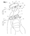
- FIG. 1 illustrates a vehicle seat with a conventional headrest and headrest support structure that also illustrates the hands-free device of the subject invention in two different positions of an installation procedure;
- FIG. 2 is an illustration of a preferred embodiment of the invention
- FIG. 3 is a partial illustration of the hands-free device, which depicts a portion of the hands-free device and the structural details of a span portion of a housing of the device and its relationship to a movable module positioned on a strap;
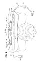
- FIG. 4 is a top view of the hands-free device as shown in FIG. 1 when the device is in a position during installation between a headrest and a top of the vehicle seat, behind a neck and head of a mobile phone user;
- FIG. 5 is a top view of the hands-free device of FIG. 4 wherein the hands-free device is shown secured to a support structure of the headrest;
- FIG. 6 illustrates a movable clip module as depicted in FIG. 2 with the strap shown in FIG. 2 removed;
- FIG. 7 is a full section of the movable clip module of FIG. 6 taken along the line 7-7;
- FIG. 8 is a clip element of the movable module of FIG. 6;
- FIG. 9 shows the movable clip module of FIG. 2 shown in isolation from other components of the preferred embodiment of the invention.
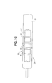
- FIG. 10 is a view of the details of the hands-free device span portion as depicted in FIG. 3.
- FIG. 1 illustrates a vehicle seat 10 with a conventional headrest 11 and headrest support structure that is comprised of a pair of support pillars 12, 13, that engage the top of the vehicle seat as shown.
- the headrest 11 is movable up and down by means of a mechanism integral with the seat and not shown in FIG. 1, as it forms no part of this invention.
- a hands-free assembly 16 embodying a preferred configuration of the invention, is shown above the headrest 11 in a position just prior to installation.
- the hands-free assembly includes a strap 17, a movable module 18, a strap fastener buckle 19 and the hands-free device 20.
- the movable module 18 is movable in the directions indicated by double ended directional arrow 15.
- the hands-free device 20 includes an elongated housing 21, which includes a speaker 22, schematically shown as a plurality of vertical, unreferenced openings in the front of the elongated housing 21.
- a microphone assembly 23 that includes an adjustable flexible arm 24, which may be of the goose neck type.
- a microphone 26 is shown located at the end of the flexible arm 24.
- a mobile phone 25 is depicted electrically coupled to the hands-free device 20 by means of a cable 27.
- arrow 28 is present. The arrow 28 is intended to indicate the direction the hands-free assembly 16 is to travel, as it moves to an initial, unsecured position beneath the headrest and the top of the vehicle seat 10 as is shown in FIG.1.
- the hands-free device 20 with its speaker 22 in the elongated housing 21 and microphone assembly 16 are shown in detail as in FIG. 1.
- the strap fastener buckle 19 is shown secured to the strap 17 and is conventional in its construction and for that reason will not be described in detail.
- the strap 17 is made of a rubbery material with an inner fabric lining.
- the circuit board may provide a number of functions, such as, but not limited to, ensuring that the hands-free device is electronically compatible with the mobile phone. Because the circuit board draws its power from mobile phone 28 via cable 25, it may provide any number of functions, such as changing the volume of the speaker by means of a voice command, or such exotic functions as suppressing background noise for the microphone 26.
- the movable clip module 18 is shown mounted on the strap 17 for sliding movement along the strap 17. This movement is accomplished by manually gripping the movable module 18 with one's fingers while the strap is in a stationary position as will be described more fully hereinafter.
- FIG. 2 The visual perspective of FIG. 2 allows the viewer to observe the entire elongated housing 21 of the hands-free device 20 as well as what will be referred to in the description that follows is a span portion 35 on the back of the elongated housing 21.
- a full view of the span portion 35 is presented in FIG. 3 and in a plan view in FIG. 10. The manner in which the strap 17 cooperates with span portion 35 will be explained in some detail hereinafter.
- FIG. 2 A number of structural features of the movable module 18 are also discernable in FIG. 2, such as a movable module cover 45, which may be fabricated from plastic or other injection moldable material.
- a downwardly projecting mating metal clip element 46 is also shown. This mating clip element 46 and its related structure are shown in detail in FIG. 8, which will be described subsequently in the specification.
- An upwardly projecting strap retaining element 47 and downwardly projecting strap retaining element 48 are provided to cooperate with the strap 17, to permit the movable module 18 to slide over the strap 17.
- the housing span portion 35 is structurally configured at a central region 36 to receive the mating metal clip element 46 of the movable module 18, all of which will be described more fully later on in the specification.
- FIG. 3 depicts a portion of the hands-free device 21 positioned on strap 17, and shows in greater structural detail the span portion 35 and its relationship to the movable module 18, which is also shown on the strap 17, juxtaposed the span portion 35.
- FIG. 4 is a top view of the hands-free device 21 as shown in FIG. 1, when the device 21, with its speaker 22, is in a position during installation behind the head and neck of a vehicle occupant shown in dotted outline.
- a centerline 29 of the elongated hands-free device 21 is shown positioned such that a projection of a line coincident with the centerline 29 of the device 21 intersects the pillars 12 ,13 in a generally perpendicular manner.
- the headrest has been removed and only the support pillars 12 and 13 are shown in section.
- FIG. 5 shows the movable module 18 locked in place in the span portion 35. At the moment the movable module 18 is fastened to the housing span portion 35, the strap 17 then takes on an overall "8" shaped configuration around the support pillars 12 and 13.
- the strap 17 around the pillars 12, 13, and the movable module 18 locked into the central region 36 of the span portion 35 provide a connecting structure that couples the hands-free device 20 to the connecting structure and simultaneously allows the connecting structure to engage the vehicle seat headrest support structure.
- pillars 12, 13 secure the speaker 22 and microphone 26 to a place adjacent the head of an occupant of the seat 10 to allow the seat occupant to hear communications via the mobile phone 25 and the speaker 22 of the hands-free device, while the occupant may simultaneously respond via the microphone 26 of the hands-free device 21.
- connecting structure of the preferred embodiment is but one of many connecting structures that may be employed in the practice of the invention, as defined in the claims appended to the specification.
- the connecting structure of the preferred embodiment employs a strap and a movable clip module secured to a span portion of the housing of the hands-free device.
- the invention is intended to include, for example, in place of the movable clip module and span portion, a hook and loop fastener, where a surface of a strap secured to and adjacent the hands-free housing is provided with loop surface configuration and the strap that passes around the headrest support pillars is provided on its back side with a hook configured surface to engage and integrally secure the hands-free device in much the same fashion as the structure of the preferred embodiment of the invention previously described.
- the invention is intended to include as within the purview of the claims a strap that is strongly elastic in its composition such that the connecting structure function is accomplished by means of the inherent elasticity of the strap which, when secured to the hands-free device and around the support pillars, would similarly hold the hands-free device stably for use by a vehicle phone user.
- the invention further entertains as falling within the scope and spirit of the claimed invention the use of a hook shaped element that may be secured to the housing of the hands-free device by means of a resilient strap, such that when the hook element is manually secured to a headrest support pillar and the housing is provided with a second hook secured to the hands-free housing, the pair of hooks will cooperate to hold the hands-free device in a stable relation between the headrest and the top of a seat behind the head and neck region of an occupant of the vehicle seat.
- connection structure were secured in part to the hands-free device and included a pair of resiliently-biased-apart, interconnected, headrest-pillar-engaging elements that would allow the pillar-engaging elements to be drawn towards each other and then released to be resiliently biased into cooperation with the headrest support pillars.
- This just described arrangement would also provide connecting structure that would be embraced by the spirit of the invention.
- FIGS. 6, 7, 8 and 9 should be studied together in conjunction with the description that follows.
- FIG. 8 illustrates in some detail the overall structure of the movable clip module 18.
- the module 18 is comprised of module cover 45 which, as has been noted earlier, may be fashioned of a plastic material. Secured within the module cover 45 is a metal clip element 44, shown in isolation in FIG. 8.
- the metal clip element 44 is provided with a passageway 50, through which the downwardly projecting strap element 48 is formed by conventional injection molding at the time the module cover 45 is formed.
- the clip element is shown in the cross-section of FIG. 7.
- the module cover 45 may be injection molded around the metal clip element 44 to thereby form the movable module 18, as is depicted in FIG. 6.
- FIG. 10 it will be observed that there is shown in some detail the span portion 35 on the backside of the elongated housing 21 of the hands-free device 20.
- the span portion 35 of the elongated housing 21 is secured at two points 31, 32 to the housing 21. At these two points 31, 32, the span portion 35 and housing 21 cooperate to allow the strap 17 to pass between the span portion 35 and the housing 21.
- This structured arrangement causes the hands-free device to maintain a substantially parallel relationship along the cover of the device and a portion of the strap 17 sandwiched between the span portion 35 and the housing 21.
- the instant invention also embraces a method of use of the mobile phone hands-free speaker and microphone assembly 16 with the vehicle seat 10, headrest 11 and seat headrest support structure (pillars 12 and 13).
- the method broadly includes the following steps.
- the strap 17 then passing around the support structure (12, 13), whereupon the strap 17 is fastened to itself to thereby provide a physically stable arrangement with the hands-free device 16 secured between the headrest 11 and the seat 10, to be in close proximity to a neck and head of a mobile phone user in the seat 10.
- the invention entails positioning a generally elongated hands-free speaker and microphone device adjacent the pair of headrest support pillars 12, 13, such that a projection of a line coincident with a center line of the elongated device intersects the pair of pillars 12, 13 in a generally perpendicular manner.
- the method further involves securing the elongated device to the pair of pillars 12, 13 to thereby constrain the device positionally to be in a parallel relationship with the center line of the device and in a generally perpendicular relationship to the pillars 12, 13, to thereby provide a physically stable arrangement with the hands-free device 16 secured to the headrest 11 and seat 10 via the pillars 12, 13 in close proximity to the neck and head of a mobile phone user employing the device when the mobile phone user/occupant is in the vehicle seat 10.
Landscapes
- Engineering & Computer Science (AREA)
- Mechanical Engineering (AREA)
- Fittings On The Vehicle Exterior For Carrying Loads, And Devices For Holding Or Mounting Articles (AREA)
- Chair Legs, Seat Parts, And Backrests (AREA)
- Seats For Vehicles (AREA)
Abstract
Description
- This invention relates to a hands-free device that includes a speaker and a microphone and is used with a mobile phone and a vehicle seat headrest support structure.
- In recent years the world wide massive proliferation of mobile phone sales and their use in a myriad of environments, especially motor vehicles, has greatly increased safety concerns when vehicle drivers attempt to use their phones while driving. These concerns center on the obvious need for the vehicle driver to keep both hands on the steering wheel, rather than holding a mobile phone to their ear with one hand while steering in congested traffic conditions. More and more countries are passing laws that prohibit drivers from using mobile phones while they drive if both hands are not completely free to steer and engage steering column mounted controls such as lights, turn signals and windshield wipers, not to mention a host of dashboard mounted controls for such accessories as radio, CD and tape player as well as heating and air conditioning.
- In response to these laws there now exist a host of mobile phone kits that allow drivers to secure their mobile phones to portable devices that hold the mobile phones separate from the drivers, usually in the region of the vehicle's dashboard. These mobile phone kits are frequently quite ingenious in their use of cigarette lighter power receptacles to power the phone and simultaneously charge the mobile phone battery. Some kits include a speakerphone and employ a microphone that captures the voice of the driver. Other kits connect the phone to the vehicle's FM radio and broadcast incoming messages over the radio loud speakers. Still others utilize handsets equipped with a microphone and ear phones. More recently the need for a hands-free mobile phone has been answered by incorporating a loud speaker in a vehicle headrest and mounting a microphone on the sun visor or on a flexible arm, which may be attached under the roof. European Patent EP0715 575 B1 granted November 11, 1998 teaches the idea of incorporating a separate loud speaker in a vehicle headrest to be adjacent the user's ear. The loud speaker is provided with connections which are connected by wiring to the mobile phone. A microphone arranged on a flexible arm is rotatably mounted on the headrest.
- As noted just above a majority of the hands-free kit type devices are designed to be installed on the center console or dashboard of a vehicle, which is located far from the head position of the driver. The ambient noise in a vehicle operating environment inherently reduces the voice pick-up and audio performance of this type of hands-free arrangement. The down side of this type of arrangement occurs when the other party to a conversation with a vehicle phone user complains of difficulty hearing. The usual response of the vehicle phone user is to shout in the direction of the dash-mounted, hands-free device. Rarely does shouting improve the clarity of the driver's voice. The listener at the other end of the call continues to express difficulty discerning the words of the vehicle phone user, which is generally followed by even louder shouting, coupled with a marked slowing down of speech.
- Another hands-free approach, for use in conjunction with a vehicle headrest that is secured by means of pillars between the headrest and the top of the vehicle seat, employs a long mounting plate with bushings of different inner diameters. First the user selects a particular pair of bushings with the same inner diameter as that of the pillars that support the headrest. This is followed by the user removing the headrest with the integrally included pillars. The mounting bushings are then mounted upon the pillars followed by locating the pillars with matching bushings into the mounting plate prior to reinstalling the pillars into the top of the seat. A speaker and microphone, which are electrically coupled to the mobile phone, are then secured to the mounting plate as well.
- Yet another hands-free approach that involves the use of a headrest support pillar calls for the use of a mounting plate that integrally includes a small swing arm that incorporates a speaker. The mounting plate involves the use of a single pillar and employs various sized bushings mounted in the plate to accommodate different diameter headrest pillar sizes. In this arrangement a microphone of the device is placed on the vehicle dashboard and both the speaker and microphone are electrically coupled to the mobile phone. The location of the microphone on the dashboard produces the same problem with the transmission of the vehicle driver's voice noted above.
- It should be readily apparent that a hands-free speaker/microphone combination integrated into a headrest cannot be detached and moved from vehicle to vehicle, since currently there is no standardization in headrest/pillar support structure dimensions. Inherent in some of the just described approaches is unavoidable inconvenience: the need to have on hand a variety of different sized bushings and the necessity of removing the headrest and support pillars to install the hands-free arrangements.
- The instant invention avoids all of the problems involved with the prior art approaches. It is remarkably simple and exceedingly expeditious to use universally with virtually any headrest support structure, irrespective of the exact structural nature of the headrest support structure, in almost all vehicles.
- The hands-free device of the instant invention is intended for use with a mobile phone and a vehicle seat support structure. The device includes a speaker and a microphone for use in combination with a connecting structure. The device is coupled to the connecting structure, allowing the connecting structure to engage the vehicle seat headrest support structure with the speaker and microphone adjacent the head of an occupant of the seat. The seat occupant is thereby able to hear information communicated via a mobile phone electrically coupled to the speaker of the hands-free device, while simultaneously allowing the occupant to communicate via the microphone of the device.
- More specifically, the hands-free device is intended for use with a mobile phone and a vehicle headrest support structure of the type that includes a pair of pillars that extend from the headrest into a top portion of a vehicle seat. The device is comprised of a generally elongated shaped housing that includes therein a speaker, and is provided at one end thereof with a microphone assembly. In a preferred embodiment the elongated shaped housing is provided with a strap-securing structure that accommodates a strap end that passes through the strap-securing structure and around both pillars to be secured with a strap fastener at another end of the strap, to thereby secure the device between the pillars and intermediate the headrest at the top of the seat. The strap-securing structure includes a span portion that is in part coupled to the strap over a section of the strap to thereby ensure that the elongated housing of the device is physically secured to and stably aligned with the strap in a generally parallel relationship to the strap over the strap section. The elongated housing portion that spans the strap section does so in such a manner that the device and strap are slidably secured relative to each other. The strap section resides between the elongated housing and the housing span portion, which is structurally configured to provide a region thereof adapted to receive a mating portion of a module fastener. A movable module is secured to the strap for movement on the strap. The module is provided with a mating fastener portion that allows the module to be fastened to the mating portion of the housing span portion after the device, strap and strap fastener have been secured as a unit to the pillar support structure of the headrest. When the device is secured to the pair of pillars the strap extends from the strap fastener, as noted above, around a pillar, to and through the span portion of the device and then around the other pillar and then through the movable module secured thereto and finally returning to a secured relationship with the strap fastener.
- At the moment the movable module is fastened to the housing span portion, the strap takes on an overall figure "8" shaped configuration around the support pillars. A highly stable physical relationship is thereby established between the device, the strap and pillars behind the neck and head of a vehicle occupant.
- A microphone assembly comprised of a flexible arm having a microphone at one end is provided at one end of the elongated housing. The flexible arm and microphone are manually positionable to allow the occupant in the vehicle seat to adjust the microphone location to proximate the mouth of the occupant.
- The invention further broadly embraces a method of providing a mobile phone hands-free speaker and microphone for use with a vehicle seat, headrest and headrest support structure of the type comprised of a pair of pillars that structurally connect the headrest and a top of the vehicle seat. More particularly the method is comprised of the following steps. First, positioning a generally elongated hands-free speaker and microphone device adjacent the pair of pillars such that a projection of a line coincident with a centerline of the elongated device intersects the pair of pillars in a generally perpendicular manner.
- Second, securing the elongated device to the pair of pillars to thereby constrain the device positionally to be in a parallel relationship with the centerline of the device and in a generally perpendicular relationship to the pillars to thereby provide a physically stable arrangement with the hands-free device secured to the headrest and seat via the pillars in close proximity to the neck and head of a mobile phone user employing the device when the mobile phone user/occupant is in the vehicle seat.
- A primary advantage/objective of this invention resides in its effortless utility. It provides a hands-free device having a speaker and microphone for use with a mobile phone and a vehicle seat headrest support structure wherein the hands-free device is highly portable and is nearly universal in its use with a wide range of vehicle headrest support structures.
- Another advantage/objective of this invention resides in the provision of a hands-free device having a speaker and microphone that easily mounts on almost any headrest support structure in a highly physically stable relationship with the speaker adjacent the neck of an occupant/driver while simultaneously providing an easily positionable microphone proximate the mouth of the driver.
- Yet another object/advantage of the invention resides in its ease and convenience. A simple, two-step method secures a mobile phone hands-free speaker microphone for use with a vehicle seat, headrest and seat headrest support structure of the type comprised of a pair of pillars that structurally connect the headrest and a top of the vehicle seat by first positioning a generally elongated hands-free speaker and microphone device adjacent the pillar such that projection of a line coincident with a centerline of the elongated device intersects the pair of pillars in a perpendicular manner, followed by securing the elongated device to the pillars such that the device is constrained in a stable manner to the pillars in close proximity to the neck and head of a mobile phone user employing the device when the phone user/occupant is in the vehicle seat.
- The present invention is further described in the detailed description which follows in reference to the noted plurality of drawings by way of non-limiting examples of embodiments of the present invention in which like reference numerals represent similar parts throughout the several views of the drawings and wherein:
- FIG. 1 illustrates a vehicle seat with a conventional headrest and headrest support structure that also illustrates the hands-free device of the subject invention in two different positions of an installation procedure;
- FIG. 2 is an illustration of a preferred embodiment of the invention;
- FIG. 3 is a partial illustration of the hands-free device, which depicts a portion of the hands-free device and the structural details of a span portion of a housing of the device and its relationship to a movable module positioned on a strap;
- FIG. 4 is a top view of the hands-free device as shown in FIG. 1 when the device is in a position during installation between a headrest and a top of the vehicle seat, behind a neck and head of a mobile phone user;
- FIG. 5 is a top view of the hands-free device of FIG. 4 wherein the hands-free device is shown secured to a support structure of the headrest;
- FIG. 6 illustrates a movable clip module as depicted in FIG. 2 with the strap shown in FIG. 2 removed;
- FIG. 7 is a full section of the movable clip module of FIG. 6 taken along the line 7-7;
- FIG. 8 is a clip element of the movable module of FIG. 6;
- FIG. 9 shows the movable clip module of FIG. 2 shown in isolation from other components of the preferred embodiment of the invention; and
- FIG. 10 is a view of the details of the hands-free device span portion as depicted in FIG. 3.
- Reference is now made to FIG. 1 which illustrates a
vehicle seat 10 with aconventional headrest 11 and headrest support structure that is comprised of a pair ofsupport pillars headrest 11 is movable up and down by means of a mechanism integral with the seat and not shown in FIG. 1, as it forms no part of this invention. A hands-free assembly 16, embodying a preferred configuration of the invention, is shown above theheadrest 11 in a position just prior to installation. The hands-free assembly includes astrap 17, amovable module 18, astrap fastener buckle 19 and the hands-free device 20. Themovable module 18 is movable in the directions indicated by double endeddirectional arrow 15. The hands-free device 20 includes anelongated housing 21, which includes aspeaker 22, schematically shown as a plurality of vertical, unreferenced openings in the front of theelongated housing 21. At the right hand of the hands-free device 20 there is portrayed amicrophone assembly 23 that includes an adjustableflexible arm 24, which may be of the goose neck type. Amicrophone 26 is shown located at the end of theflexible arm 24. Amobile phone 25 is depicted electrically coupled to the hands-free device 20 by means of acable 27. Immediately beneath the hands-free assembly 16 anarrow 28 is present. Thearrow 28 is intended to indicate the direction the hands-free assembly 16 is to travel, as it moves to an initial, unsecured position beneath the headrest and the top of thevehicle seat 10 as is shown in FIG.1. The hands-free device 20 with itsspeaker 22 in theelongated housing 21 andmicrophone assembly 16 are shown in detail as in FIG. 1. Thestrap fastener buckle 19 is shown secured to thestrap 17 and is conventional in its construction and for that reason will not be described in detail. In this, the preferred embodiment of the invention, thestrap 17 is made of a rubbery material with an inner fabric lining. Although not shown, within the interior of theelongated housing 21, in addition to thespeaker 22, there may be an electronic circuit board. The circuit board may provide a number of functions, such as, but not limited to, ensuring that the hands-free device is electronically compatible with the mobile phone. Because the circuit board draws its power frommobile phone 28 viacable 25, it may provide any number of functions, such as changing the volume of the speaker by means of a voice command, or such exotic functions as suppressing background noise for themicrophone 26. - The
movable clip module 18 is shown mounted on thestrap 17 for sliding movement along thestrap 17. This movement is accomplished by manually gripping themovable module 18 with one's fingers while the strap is in a stationary position as will be described more fully hereinafter. - The visual perspective of FIG. 2 allows the viewer to observe the entire
elongated housing 21 of the hands-free device 20 as well as what will be referred to in the description that follows is aspan portion 35 on the back of theelongated housing 21. A full view of thespan portion 35 is presented in FIG. 3 and in a plan view in FIG. 10. The manner in which thestrap 17 cooperates withspan portion 35 will be explained in some detail hereinafter. It is sufficient to note at this point in the description of the invention that functionally thespan portion 35 of theelongated housing 21 is coupled to thestrap 17 over a section of the strap to thereby ensure that the elongated housing of the hands-free device 20 is physically secured to and stably aligned with thestrap 17 in a generally parallel relationship to the strap over the strap section. It will be further appreciated from a study of subsequent figures that the hands-free device and the strap are slidably secured relative to each other. - A number of structural features of the
movable module 18 are also discernable in FIG. 2, such as amovable module cover 45, which may be fabricated from plastic or other injection moldable material. A downwardly projecting matingmetal clip element 46 is also shown. Thismating clip element 46 and its related structure are shown in detail in FIG. 8, which will be described subsequently in the specification. An upwardly projectingstrap retaining element 47 and downwardly projectingstrap retaining element 48 are provided to cooperate with thestrap 17, to permit themovable module 18 to slide over thestrap 17. Thehousing span portion 35 is structurally configured at acentral region 36 to receive the matingmetal clip element 46 of themovable module 18, all of which will be described more fully later on in the specification. - FIG. 3 depicts a portion of the hands-
free device 21 positioned onstrap 17, and shows in greater structural detail thespan portion 35 and its relationship to themovable module 18, which is also shown on thestrap 17, juxtaposed thespan portion 35. - The description that follows is directed to the subject matter of FIG. 4 and FIG. 5. FIG. 4 is a top view of the hands-
free device 21 as shown in FIG. 1, when thedevice 21, with itsspeaker 22, is in a position during installation behind the head and neck of a vehicle occupant shown in dotted outline. Acenterline 29 of the elongated hands-free device 21 is shown positioned such that a projection of a line coincident with thecenterline 29 of thedevice 21 intersects thepillars support pillars free assembly 16 of FIG. 1 has been lowered into the position in FIG. 4 and thestrap 17 has been pulled in the direction indicated byarrow 30, all slack instrap 17 will be removed. Theslidable module 18 may then be positioned juxtaposed to thecentral region 36 of thespan portion 35, as shown in FIG. 3. Themetal clip element 46, better seen in FIG. 2, may then be manually moved to matingly engage thecentral region 36 of thespan portion 35 of theelongated housing 21. FIG. 5 shows themovable module 18 locked in place in thespan portion 35. At the moment themovable module 18 is fastened to thehousing span portion 35, thestrap 17 then takes on an overall "8" shaped configuration around thesupport pillars strap 17 around thepillars movable module 18 locked into thecentral region 36 of thespan portion 35 provide a connecting structure that couples the hands-free device 20 to the connecting structure and simultaneously allows the connecting structure to engage the vehicle seat headrest support structure. Inother words pillars speaker 22 andmicrophone 26 to a place adjacent the head of an occupant of theseat 10 to allow the seat occupant to hear communications via themobile phone 25 and thespeaker 22 of the hands-free device, while the occupant may simultaneously respond via themicrophone 26 of the hands-free device 21. - It is important to recognize that the just described connecting structure of the preferred embodiment is but one of many connecting structures that may be employed in the practice of the invention, as defined in the claims appended to the specification. For example, while the connecting structure of the preferred embodiment employs a strap and a movable clip module secured to a span portion of the housing of the hands-free device. The invention is intended to include, for example, in place of the movable clip module and span portion, a hook and loop fastener, where a surface of a strap secured to and adjacent the hands-free housing is provided with loop surface configuration and the strap that passes around the headrest support pillars is provided on its back side with a hook configured surface to engage and integrally secure the hands-free device in much the same fashion as the structure of the preferred embodiment of the invention previously described. In a similar manner the invention is intended to include as within the purview of the claims a strap that is strongly elastic in its composition such that the connecting structure function is accomplished by means of the inherent elasticity of the strap which, when secured to the hands-free device and around the support pillars, would similarly hold the hands-free device stably for use by a vehicle phone user. The invention further entertains as falling within the scope and spirit of the claimed invention the use of a hook shaped element that may be secured to the housing of the hands-free device by means of a resilient strap, such that when the hook element is manually secured to a headrest support pillar and the housing is provided with a second hook secured to the hands-free housing, the pair of hooks will cooperate to hold the hands-free device in a stable relation between the headrest and the top of a seat behind the head and neck region of an occupant of the vehicle seat. Yet another structural variation of the claimed invention would exist if the connecting structure were secured in part to the hands-free device and included a pair of resiliently-biased-apart, interconnected, headrest-pillar-engaging elements that would allow the pillar-engaging elements to be drawn towards each other and then released to be resiliently biased into cooperation with the headrest support pillars. This just described arrangement would also provide connecting structure that would be embraced by the spirit of the invention.
- FIGS. 6, 7, 8 and 9 should be studied together in conjunction with the description that follows.
- FIG. 8 illustrates in some detail the overall structure of the
movable clip module 18. Themodule 18 is comprised ofmodule cover 45 which, as has been noted earlier, may be fashioned of a plastic material. Secured within themodule cover 45 is ametal clip element 44, shown in isolation in FIG. 8. Themetal clip element 44 is provided with apassageway 50, through which the downwardly projectingstrap element 48 is formed by conventional injection molding at the time themodule cover 45 is formed. The clip element is shown in the cross-section of FIG. 7. Themodule cover 45 may be injection molded around themetal clip element 44 to thereby form themovable module 18, as is depicted in FIG. 6. FIG. 9, in a manner similar to FIG. 2, shows thestrap 17 in place in themovable clip module 18. - Turning now to FIG. 10 it will be observed that there is shown in some detail the
span portion 35 on the backside of theelongated housing 21 of the hands-free device 20. It will be noted thespan portion 35 of theelongated housing 21 is secured at twopoints housing 21. At these twopoints span portion 35 andhousing 21 cooperate to allow thestrap 17 to pass between thespan portion 35 and thehousing 21. This structured arrangement causes the hands-free device to maintain a substantially parallel relationship along the cover of the device and a portion of thestrap 17 sandwiched between thespan portion 35 and thehousing 21. - It follows from the description above that the wider the strap is relative to the width of the back of the hands-free device and the greater the distance between
points span portion 35 is at least as long as thestrap 17 is wide. - The instant invention also embraces a method of use of the mobile phone hands-free speaker and
microphone assembly 16 with thevehicle seat 10,headrest 11 and seat headrest support structure (pillars 12 and 13). The method broadly includes the following steps. - First, positioning the generally elongated hands-free speaker and
microphone assembly 16, the headrest support structure that structurally interconnects theseat 10 andheadrest 11, and then securing the elongated device to the headrest support structure by means of astrap 17 that passes through a portion of the device in at least two, spaced apart locations. Thestrap 17 then passing around the support structure (12, 13), whereupon thestrap 17 is fastened to itself to thereby provide a physically stable arrangement with the hands-free device 16 secured between theheadrest 11 and theseat 10, to be in close proximity to a neck and head of a mobile phone user in theseat 10. - More specifically the invention entails positioning a generally elongated hands-free speaker and microphone device adjacent the pair of
headrest support pillars pillars pillars pillars free device 16 secured to theheadrest 11 andseat 10 via thepillars vehicle seat 10. - Although the present invention has been described herein with reference to a particular method, materials and embodiments, the present invention is not intended to be limited to the particulars disclosed herein. Rather, the present invention extends to all functionally equivalent structures, methods and use, such as are within the scope of the appended claims.
Claims (34)
- A hands-free device for use with a mobile phone and a vehicle seat headrest support structure, the device includes a speaker and a microphone assembly for use in combination with a connecting structure that couples the device to the connecting structure and simultaneously allows the connecting structure to engage the vehicle seat headrest support structure to secure the speaker and microphone assembly adjacent a head of an occupant of the seat to thereby allow the seat occupant to hear information communicated via the mobile phone and the speaker of the hands-free device while the occupant may simultaneously communicate via a microphone of the microphone assembly.
- The hands-free device of Claim 1 wherein the connecting structure is a strap.
- The hands-free device of Claim 2 wherein the strap includes a strap fastener secured to an end of the strap, and
the device has an elongated housing that includes a span portion that is in part coupled to the strap over a section of the strap to thereby ensure that the elongated housing of the device is physically secured to and stably aligned with the strap in a generally parallel relationship to the strap over the strap section. - The hands-free device of Claim 3 wherein the span portion is at least as long as the strap is wido.
- The hands-free device of Claim 3 wherein the elongated housing portion that spans the strap section does so in such a manner that the device and strap are slidably secured relative to each other.
- The hands-free device of Claim 5 wherein the strap section resides between the housing span portion and the elongated housing.
- The hands-free device of Claim 6 wherein the housing span portion is structurally configured to provide a region thereof adapted to receive a mating portion of the fastener.
- The hands-free device of Claim 7 wherein the module fastener is movable and is secured to the strap for movement on the strap,
the movable module fastener is provided with a mating fastener portion that allows the module fastener to be fastened to the region of the housing span portion that is adapted to receive the mating portion of the module fastener after the device, strap and strap fastener have been secured as a unit to the support structure of the headrest. - The hands-free device of Claim 8 wherein the fastener portion of the module is of the clip type and includes a clip portion thereof that engages the housing span portion to thereby secure the device and a portion of the strap to the module slidably secured to the strap.
- The hands-free device of Claim 9 wherein the headrest support structure is comprised of a pair of separated support pillars that couple the headrest to the vehicle seat,
the strap extending from the strap fastener around a pillar, to and through the span portion of the device and then around the other pillar and through the movable module secured thereto and finally returning to a secured relationship with the strap fastener,
at the moment the movable module is fastened to the housing span portion, the strap then takes on an overall "8" shaped configuration around the support pillars, thereby establishing a highly stable physical relationship between the device, the strap and pillars behind the neck and head of a vehicle occupant. - The hands-free device of Claim 10 wherein the elongated housing is adapted to support the speaker in such a manner that sound from the speaker exits the housing proximate a neck and head region of the occupant.
- The hands-free device of Claim 11 wherein the elongated housing is provided at one end thereof with a microphone assembly.
- The hands-free device of Claim 12 wherein the microphone assembly is comprised of a flexible arm secured at one and thereof to the elongated housing and provide at the other end with a microphone, the flexible arm and microphone are manually positionable to allow an occupant in the vehicle seat to adjust the microphone location to be proximate the mouth of the occupant.
- The hands-free device of Claim 2 wherein the strap includes a strap fastener secured to an end of the strap,
the device is coupled to the strap in at least two locations on the device and cooperates with the strap and strap fastener to allow the device to be adjustably secured to the headrest support structure. - The hands-free device of Claim 14 wherein the strap fastener is a buckle.
- The hands-free device of Claim 14 wherein the device has a housing cover that is adapted to receive the strap at the two locations in such a manner that the device and strap are slidably secured relative to each other and thereby causes the device to maintain a substantially parallel relationship along the cover of the device and a portion of the strap.
- The hands-free device of Claim 16 wherein the housing cover is provided with a span portion thereof that is integral with and spans the two locations such that a section of the strap resides between the housing cover and the housing cover span portion.
- The hands-free device of Claim 17 wherein the housing span portion is structurally configured to provide a region thereof adapted to receive a mating portion of a movable module fastener.
- The hands-free device of Claim 18 wherein the movable module fastener is secured to the strap for movement along the strap,
the module fastener is provided with a mating fastener portion that allows the module to be fastened to the mating portion of the housing span portion after the device, strap and strap fastener have been secured to the support structure of the headrest. - The hands-free device of Claim 19 wherein the fastener portion of the module is of the clip type and includes a clip portion thereof that engages the housing span portion to thereby secure the device and a portion of the strap between the two locations to the module slidably secured to the strap.
- The hands-free device of Claim 20 wherein the headrest support structure is comprised of a pair of separated support pillars that couple the headrest to the vehicle seat,
the strap extending from the strap fastener around a pillar, to and through a portion of the device at the two locations and then around the other pillar and through the movable module fastener secured thereto and finally to a secured relationship with the strap fastener,
at the moment the movable module is fastened to the housing span portion, the strap then takes on an overall "8" shaped configuration around the support pillars to thereby establish a highly stable physical relationship between the device, the strap and pillars behind a neck and head of a vehicle occupant. - The hands-free device of Claim 21 wherein in the housing cover is elongated and is adapted to support the speaker in such a manner that sound from the speaker exits the housing proximate a neck and head region of the occupant.
- The hands-free device of Claim 22 wherein the microphone assembly is of the gooseneck type.
- The hands-free device of Claim 22 wherein the microphone assembly is comprised of a flexible arm secured at one end thereof to the elongated housing and provided at the other end with a microphone, the flexible arm and microphone are manually positionable to allow an occupant in the vehicle seat to adjust the microphone location to be proximate the mouth of the occupant.
- A hands-free device for use with a the mobile phone and a vehicle seat headrest support of the type that includes a pair of pillars that extends from headrest into a top portion of a vehicle seat, the device comprising:a generally elongated shaped housing that includes therein a speaker, and is provided at one end thereof with a microphone assembly,the elongated shaped housing is provided with a strap securing structure that accommodates a strap end that passes through the strap securing structure and around both pillars to be secured with a strap fastener at another end of the strap to thereby secure the device between the pillars and intermediate the headrest and a top of the seat.
- The hands-free device of Claim 25 wherein the strap securing structure is configured to couple a region of the strap in at least two locations on the device to the strap.
- The hands-free device of Claim 26 wherein the strap securing structure at the two locations allows the device to be slidably secured relative to the strap and thereby causes the device to maintain a substantially parallel relationship along the elongated housing and the region of the strap between the two locations which ensures the speaker and microphone assembly are consistently positioned behind a neck and head of a vehicle seat occupant when seated.
- The hands-free device of Claim 27 wherein the elongated housing is provided with a span structure that is integral with and spans the two locations such that the strap when present will reside between the elongated shaped housing and the span structure.
- The hands-free device of Claim 28 wherein the span structure is configured to provide a region thereof adapted to receive a mating portion of a movable fastening unit.
- The hands-free device of Claim 29 wherein the movable fastening unit is secured to the strap for movement along the strap,
the fastening unit is provided with a mating portion that cooperates with the span structure after the device, strap and strap fastener has been secured around pillars and the fastening unit has been secured via the mating portion to the span structure. - The hands-free device of Claim 25 wherein the strap fastener is a buckle.
- A method of providing a mobile phone hands-free speaker and microphone device for use with a vehicle seat, headrest and seat/headrest support structure comprising the following steps:(a) positioning a generally elongated hands-free speaker and microphone device adjacant the headrest support structure that structurally interconnects the seat and headrest,(b) securing the elongated device to the headrest support structure by means of a strap that passes through a portion of the device in at least two spaced apart locations, the strap then passing around the support structure whereupon the strap is fastened to itself to thereby provide a physically stable arrangement with the hands-free device secured between the headrest and seat to be in close proximity to a neck and head of a mobile phone user/occupant in the vehicle seat.
- A method of providing a mobile phone hands-free speaker and microphone device for use with a vehicle seat, headrest and seat/headrest support structure comprising the following steps:(a) positioning a generally elongated hands-free speaker and microphone device adjacent the headrest support structure that interconnects the seat and the headrest,(b) securing the elongated device to the headrest support structure a means of the strap that passes through portion of the device to thereby constrained the elongated device positionally to be in a parallel configuration with the strap, the strap then passing around the support structure whereupon the strap is fastened to itself to thereby provide a physically stable arrangement with the hands-free device secured between the headrest and seat in close proximity to a neck and head of a mobile phone user/occupant in the vehicle seat.
- A method of securing a mobile phone hands-free speaker and microphone for use with a vehicle seat, headrest and seat headrest support structure of the type comprised of a pair of pillars that structurally connect the headrest and a top of the vehicle seat, the method comprising the following steps:(a) positioning a generally elongated hands-free speaker and microphone device adjacent the pair of pillars such that a projection of a line coincident with a centerline of the elongated device intersects the pair of pillars in a generally perpendicular manner,(b) securing the elongated device to the pair of pillars to thereby constrain the device positionally to be in a parallel relationship with the centerline of the device and in a generally perpendicular relationship to the pillars, to thereby provide a physically stable arrangement with the hands-free device secured to the headrest and seat via the pillars in close proximity to a neck and head of a mobile phone user employing the device when the mobile phone user/occupant is in the vehicle seat.
Applications Claiming Priority (2)
| Application Number | Priority Date | Filing Date | Title |
|---|---|---|---|
| US929023 | 2001-08-15 | ||
| US09/929,023 US7016708B1 (en) | 2001-08-15 | 2001-08-15 | Hands-free device for vehicle headrest and method of use |
Publications (2)
| Publication Number | Publication Date |
|---|---|
| EP1285818A1 true EP1285818A1 (en) | 2003-02-26 |
| EP1285818B1 EP1285818B1 (en) | 2004-10-20 |
Family
ID=25457194
Family Applications (1)
| Application Number | Title | Priority Date | Filing Date |
|---|---|---|---|
| EP02016576A Expired - Lifetime EP1285818B1 (en) | 2001-08-15 | 2002-07-24 | Hands-free device for vehicle headrest and method of use |
Country Status (4)
| Country | Link |
|---|---|
| US (1) | US7016708B1 (en) |
| EP (1) | EP1285818B1 (en) |
| AT (1) | ATE280056T1 (en) |
| DE (1) | DE60201642T2 (en) |
Cited By (3)
| Publication number | Priority date | Publication date | Assignee | Title |
|---|---|---|---|---|
| DE102004050599A1 (en) * | 2004-10-15 | 2006-04-20 | Daimlerchrysler Ag | Communications device for vehicle has holder for headset that is provided and configured for fixing in area around vehicle occupant |
| DE102006016593A1 (en) * | 2006-04-06 | 2007-10-11 | Bury Gmbh & Co. Kg | Vehicle-internal communication device for passengers of vehicle, has rear microphone directing backward, and rear loudspeaker fitted locally before rear passenger within upper region of backrest, preferably head support of front seat |
| CN107131182A (en) * | 2016-02-29 | 2017-09-05 | 福特全球技术公司 | Vehicle part with the installing component for being attached functional part |
Families Citing this family (6)
| Publication number | Priority date | Publication date | Assignee | Title |
|---|---|---|---|---|
| US8849185B2 (en) | 2003-04-15 | 2014-09-30 | Ipventure, Inc. | Hybrid audio delivery system and method therefor |
| FI7318U1 (en) * | 2006-08-11 | 2006-11-29 | Nokia Corp | Modular messaging device |
| US8320600B2 (en) * | 2009-07-21 | 2012-11-27 | Boston Scientific Neuromodulation Corporation | Method and apparatus to enhance communication in the operating room |
| US8428665B1 (en) * | 2012-07-27 | 2013-04-23 | Signal Essence, LLC | Holder for portable communication device |
| US9800068B2 (en) * | 2015-12-29 | 2017-10-24 | Eagle Fan | Portable charger with auxiliary functions |
| US11076033B1 (en) | 2020-09-29 | 2021-07-27 | Ricardo Huelga | Smart device support |
Citations (2)
| Publication number | Priority date | Publication date | Assignee | Title |
|---|---|---|---|---|
| EP0917988A1 (en) * | 1997-11-22 | 1999-05-26 | PVT Präzisions-Verbindungstechnik und Steuerungsbau GmbH | Electro-acoustic transducer |
| DE10043918A1 (en) * | 1999-09-07 | 2001-03-22 | Denso Corp | Hands-free mobile telephone system for vehicle, disposes microphone and loudspeaker on opposite sides of seat headrest |
Family Cites Families (3)
| Publication number | Priority date | Publication date | Assignee | Title |
|---|---|---|---|---|
| SE9302878L (en) | 1993-09-03 | 1995-03-04 | Volvo Ab | Device by mobile phone |
| US6094496A (en) * | 1997-08-18 | 2000-07-25 | Stowers, Sr.; Duane B. | Vehicle seat headrest incorporating speakers and an extensible/retractable microphone |
| AUPQ204099A0 (en) * | 1999-08-05 | 1999-08-26 | Amtel Technology Pty Ltd | Attachment device for a mobile phone or the like |
-
2001
- 2001-08-15 US US09/929,023 patent/US7016708B1/en not_active Expired - Lifetime
-
2002
- 2002-07-24 DE DE60201642T patent/DE60201642T2/en not_active Expired - Lifetime
- 2002-07-24 EP EP02016576A patent/EP1285818B1/en not_active Expired - Lifetime
- 2002-07-24 AT AT02016576T patent/ATE280056T1/en not_active IP Right Cessation
Patent Citations (2)
| Publication number | Priority date | Publication date | Assignee | Title |
|---|---|---|---|---|
| EP0917988A1 (en) * | 1997-11-22 | 1999-05-26 | PVT Präzisions-Verbindungstechnik und Steuerungsbau GmbH | Electro-acoustic transducer |
| DE10043918A1 (en) * | 1999-09-07 | 2001-03-22 | Denso Corp | Hands-free mobile telephone system for vehicle, disposes microphone and loudspeaker on opposite sides of seat headrest |
Cited By (4)
| Publication number | Priority date | Publication date | Assignee | Title |
|---|---|---|---|---|
| DE102004050599A1 (en) * | 2004-10-15 | 2006-04-20 | Daimlerchrysler Ag | Communications device for vehicle has holder for headset that is provided and configured for fixing in area around vehicle occupant |
| DE102004050599B4 (en) * | 2004-10-15 | 2008-06-26 | Daimler Ag | Communication device for a vehicle |
| DE102006016593A1 (en) * | 2006-04-06 | 2007-10-11 | Bury Gmbh & Co. Kg | Vehicle-internal communication device for passengers of vehicle, has rear microphone directing backward, and rear loudspeaker fitted locally before rear passenger within upper region of backrest, preferably head support of front seat |
| CN107131182A (en) * | 2016-02-29 | 2017-09-05 | 福特全球技术公司 | Vehicle part with the installing component for being attached functional part |
Also Published As
| Publication number | Publication date |
|---|---|
| ATE280056T1 (en) | 2004-11-15 |
| EP1285818B1 (en) | 2004-10-20 |
| DE60201642T2 (en) | 2005-09-08 |
| DE60201642D1 (en) | 2004-11-25 |
| US7016708B1 (en) | 2006-03-21 |
Similar Documents
| Publication | Publication Date | Title |
|---|---|---|
| DE19911244C2 (en) | Device for the safe use of a portable mobile phone when driving | |
| US6625426B2 (en) | Combined rear view mirror and telephone | |
| US6549793B1 (en) | Combined rear view mirror and telephone | |
| US6728375B1 (en) | Mirror mounted mobile telephone system | |
| US4850015A (en) | Vehicular steering wheel telephone apparatus | |
| US20110132950A1 (en) | Seat Belt Attachment | |
| EP1285818B1 (en) | Hands-free device for vehicle headrest and method of use | |
| US20120148080A1 (en) | Wide action clamping mount for communication headset to half-helmets, sports helmets, and the like | |
| GB2235607A (en) | Microphone mounting | |
| JP2014027654A (en) | Independent "handsfree" telephone device in configuration of detachable single body clamped to sun visor of automobile vehicle | |
| CN2563859Y (en) | Mobile phone hands-free device installed in the car | |
| JP3005506U (en) | Microphone speaker for communication used for mobile phones, etc. | |
| EP1317888A1 (en) | Crash helmet for use with a cellular telephone, particulary for motorcyclists | |
| JPH08324354A (en) | Holding device for cellular phone and the like for use in automobile | |
| CN221851824U (en) | Automobile mobile phone support | |
| KR200210278Y1 (en) | Fixation module for handphone connection in car | |
| JP3045092U (en) | Hands-free communication device for cars | |
| JPH089985Y2 (en) | Car phone equipment | |
| CN2430316Y (en) | Improved hands-free handset for mobile phones | |
| KR200284296Y1 (en) | Handsfree Set for Automobile | |
| JPH1117793A (en) | Onboard hands free speaking device | |
| CA2310172A1 (en) | Combined rear view mirror and telephone | |
| EP1144221A1 (en) | Loud speaker mounting arrangement | |
| KR20030006351A (en) | Apparatus for hands-free use of a mobile telephone in a car | |
| EP0980174A2 (en) | Integrated protective helmet for handsfree use of a mobile telephone in a car |
Legal Events
| Date | Code | Title | Description |
|---|---|---|---|
| PUAI | Public reference made under article 153(3) epc to a published international application that has entered the european phase |
Free format text: ORIGINAL CODE: 0009012 |
|
| AK | Designated contracting states |
Kind code of ref document: A1 Designated state(s): AT BE BG CH CY CZ DE DK EE ES FI FR GB GR IE IT LI LU MC NL PT SE SK TR |
|
| AX | Request for extension of the european patent |
Extension state: AL LT LV MK RO SI |
|
| 17P | Request for examination filed |
Effective date: 20030707 |
|
| AKX | Designation fees paid |
Designated state(s): AT BE BG CH CY CZ DE DK EE ES FI FR GB GR IE IT LI LU MC NL PT SE SK TR |
|
| 17Q | First examination report despatched |
Effective date: 20030924 |
|
| GRAP | Despatch of communication of intention to grant a patent |
Free format text: ORIGINAL CODE: EPIDOSNIGR1 |
|
| GRAS | Grant fee paid |
Free format text: ORIGINAL CODE: EPIDOSNIGR3 |
|
| GRAA | (expected) grant |
Free format text: ORIGINAL CODE: 0009210 |
|
| AK | Designated contracting states |
Kind code of ref document: B1 Designated state(s): AT BE BG CH CY CZ DE DK EE ES FI FR GB GR IE IT LI LU MC NL PT SE SK TR |
|
| PG25 | Lapsed in a contracting state [announced via postgrant information from national office to epo] |
Ref country code: EE Free format text: LAPSE BECAUSE OF FAILURE TO SUBMIT A TRANSLATION OF THE DESCRIPTION OR TO PAY THE FEE WITHIN THE PRESCRIBED TIME-LIMIT Effective date: 20041020 Ref country code: IT Free format text: LAPSE BECAUSE OF FAILURE TO SUBMIT A TRANSLATION OF THE DESCRIPTION OR TO PAY THE FEE WITHIN THE PRE;WARNING: LAPSES OF ITALIAN PATENTS WITH EFFECTIVE DATE BEFORE 2007 MAY HAVE OCCURRED AT ANY TIME BEFORE 2007. THE CORRECT EFFECTIVE DATE MAY BE DIFFERENT FROM THE ONE RECORDED.SCRIBED TIME-LIMIT Effective date: 20041020 Ref country code: SK Free format text: LAPSE BECAUSE OF FAILURE TO SUBMIT A TRANSLATION OF THE DESCRIPTION OR TO PAY THE FEE WITHIN THE PRESCRIBED TIME-LIMIT Effective date: 20041020 Ref country code: AT Free format text: LAPSE BECAUSE OF FAILURE TO SUBMIT A TRANSLATION OF THE DESCRIPTION OR TO PAY THE FEE WITHIN THE PRESCRIBED TIME-LIMIT Effective date: 20041020 Ref country code: LI Free format text: LAPSE BECAUSE OF FAILURE TO SUBMIT A TRANSLATION OF THE DESCRIPTION OR TO PAY THE FEE WITHIN THE PRESCRIBED TIME-LIMIT Effective date: 20041020 Ref country code: CH Free format text: LAPSE BECAUSE OF FAILURE TO SUBMIT A TRANSLATION OF THE DESCRIPTION OR TO PAY THE FEE WITHIN THE PRESCRIBED TIME-LIMIT Effective date: 20041020 Ref country code: CZ Free format text: LAPSE BECAUSE OF FAILURE TO SUBMIT A TRANSLATION OF THE DESCRIPTION OR TO PAY THE FEE WITHIN THE PRESCRIBED TIME-LIMIT Effective date: 20041020 Ref country code: BE Free format text: LAPSE BECAUSE OF FAILURE TO SUBMIT A TRANSLATION OF THE DESCRIPTION OR TO PAY THE FEE WITHIN THE PRESCRIBED TIME-LIMIT Effective date: 20041020 Ref country code: BG Free format text: LAPSE BECAUSE OF FAILURE TO SUBMIT A TRANSLATION OF THE DESCRIPTION OR TO PAY THE FEE WITHIN THE PRESCRIBED TIME-LIMIT Effective date: 20041020 Ref country code: TR Free format text: LAPSE BECAUSE OF FAILURE TO SUBMIT A TRANSLATION OF THE DESCRIPTION OR TO PAY THE FEE WITHIN THE PRESCRIBED TIME-LIMIT Effective date: 20041020 |
|
| REG | Reference to a national code |
Ref country code: GB Ref legal event code: FG4D |
|
| REG | Reference to a national code |
Ref country code: CH Ref legal event code: EP |
|
| REG | Reference to a national code |
Ref country code: IE Ref legal event code: FG4D |
|
| REF | Corresponds to: |
Ref document number: 60201642 Country of ref document: DE Date of ref document: 20041125 Kind code of ref document: P |
|
| PG25 | Lapsed in a contracting state [announced via postgrant information from national office to epo] |
Ref country code: DK Free format text: LAPSE BECAUSE OF FAILURE TO SUBMIT A TRANSLATION OF THE DESCRIPTION OR TO PAY THE FEE WITHIN THE PRESCRIBED TIME-LIMIT Effective date: 20050120 Ref country code: GR Free format text: LAPSE BECAUSE OF FAILURE TO SUBMIT A TRANSLATION OF THE DESCRIPTION OR TO PAY THE FEE WITHIN THE PRESCRIBED TIME-LIMIT Effective date: 20050120 Ref country code: SE Free format text: LAPSE BECAUSE OF FAILURE TO SUBMIT A TRANSLATION OF THE DESCRIPTION OR TO PAY THE FEE WITHIN THE PRESCRIBED TIME-LIMIT Effective date: 20050120 |
|
| PG25 | Lapsed in a contracting state [announced via postgrant information from national office to epo] |
Ref country code: ES Free format text: LAPSE BECAUSE OF FAILURE TO SUBMIT A TRANSLATION OF THE DESCRIPTION OR TO PAY THE FEE WITHIN THE PRESCRIBED TIME-LIMIT Effective date: 20050131 |
|
| REG | Reference to a national code |
Ref country code: CH Ref legal event code: PL |
|
| RIN2 | Information on inventor provided after grant (corrected) |
Inventor name: CHAN, ARNOLD YUK FUNG Inventor name: WONG, ALAN KA LUN Inventor name: JOKINEN, TAPANI Inventor name: EROMA, VALTTERI Inventor name: SADE, HELI |
|
| REG | Reference to a national code |
Ref country code: GB Ref legal event code: 711B |
|
| PG25 | Lapsed in a contracting state [announced via postgrant information from national office to epo] |
Ref country code: LU Free format text: LAPSE BECAUSE OF NON-PAYMENT OF DUE FEES Effective date: 20050724 Ref country code: CY Free format text: LAPSE BECAUSE OF FAILURE TO SUBMIT A TRANSLATION OF THE DESCRIPTION OR TO PAY THE FEE WITHIN THE PRESCRIBED TIME-LIMIT Effective date: 20050724 |
|
| PG25 | Lapsed in a contracting state [announced via postgrant information from national office to epo] |
Ref country code: IE Free format text: LAPSE BECAUSE OF NON-PAYMENT OF DUE FEES Effective date: 20050725 |
|
| PG25 | Lapsed in a contracting state [announced via postgrant information from national office to epo] |
Ref country code: MC Free format text: LAPSE BECAUSE OF NON-PAYMENT OF DUE FEES Effective date: 20050731 |
|
| PLBE | No opposition filed within time limit |
Free format text: ORIGINAL CODE: 0009261 |
|
| STAA | Information on the status of an ep patent application or granted ep patent |
Free format text: STATUS: NO OPPOSITION FILED WITHIN TIME LIMIT |
|
| ET | Fr: translation filed | ||
| 26N | No opposition filed |
Effective date: 20050721 |
|
| REG | Reference to a national code |
Ref country code: GB Ref legal event code: 711G |
|
| REG | Reference to a national code |
Ref country code: IE Ref legal event code: MM4A |
|
| PG25 | Lapsed in a contracting state [announced via postgrant information from national office to epo] |
Ref country code: PT Free format text: LAPSE BECAUSE OF NON-PAYMENT OF DUE FEES Effective date: 20050320 |
|
| PGFP | Annual fee paid to national office [announced via postgrant information from national office to epo] |
Ref country code: NL Payment date: 20100707 Year of fee payment: 9 |
|
| PGFP | Annual fee paid to national office [announced via postgrant information from national office to epo] |
Ref country code: DE Payment date: 20100721 Year of fee payment: 9 Ref country code: FI Payment date: 20100712 Year of fee payment: 9 Ref country code: FR Payment date: 20100805 Year of fee payment: 9 |
|
| PGFP | Annual fee paid to national office [announced via postgrant information from national office to epo] |
Ref country code: GB Payment date: 20100721 Year of fee payment: 9 |
|
| REG | Reference to a national code |
Ref country code: NL Ref legal event code: V1 Effective date: 20120201 |
|
| GBPC | Gb: european patent ceased through non-payment of renewal fee |
Effective date: 20110724 |
|
| REG | Reference to a national code |
Ref country code: FR Ref legal event code: ST Effective date: 20120330 |
|
| PG25 | Lapsed in a contracting state [announced via postgrant information from national office to epo] |
Ref country code: DE Free format text: LAPSE BECAUSE OF NON-PAYMENT OF DUE FEES Effective date: 20120201 Ref country code: FR Free format text: LAPSE BECAUSE OF NON-PAYMENT OF DUE FEES Effective date: 20110801 |
|
| REG | Reference to a national code |
Ref country code: DE Ref legal event code: R119 Ref document number: 60201642 Country of ref document: DE Effective date: 20120201 |
|
| PG25 | Lapsed in a contracting state [announced via postgrant information from national office to epo] |
Ref country code: NL Free format text: LAPSE BECAUSE OF NON-PAYMENT OF DUE FEES Effective date: 20120201 Ref country code: FI Free format text: LAPSE BECAUSE OF NON-PAYMENT OF DUE FEES Effective date: 20110724 |
|
| PG25 | Lapsed in a contracting state [announced via postgrant information from national office to epo] |
Ref country code: GB Free format text: LAPSE BECAUSE OF NON-PAYMENT OF DUE FEES Effective date: 20110724 |