EP1285806A2 - Power take-off clutch control system - Google Patents
Power take-off clutch control system Download PDFInfo
- Publication number
- EP1285806A2 EP1285806A2 EP02013246A EP02013246A EP1285806A2 EP 1285806 A2 EP1285806 A2 EP 1285806A2 EP 02013246 A EP02013246 A EP 02013246A EP 02013246 A EP02013246 A EP 02013246A EP 1285806 A2 EP1285806 A2 EP 1285806A2
- Authority
- EP
- European Patent Office
- Prior art keywords
- clutch
- pto clutch
- pto
- pressure
- control valve
- Prior art date
- Legal status (The legal status is an assumption and is not a legal conclusion. Google has not performed a legal analysis and makes no representation as to the accuracy of the status listed.)
- Granted
Links
- 230000005540 biological transmission Effects 0.000 claims abstract description 22
- 238000000034 method Methods 0.000 claims abstract description 17
- 230000006870 function Effects 0.000 claims description 11
- 238000012886 linear function Methods 0.000 claims description 7
- 238000004891 communication Methods 0.000 claims description 2
- 239000012530 fluid Substances 0.000 description 7
- 230000007423 decrease Effects 0.000 description 5
- 230000003466 anti-cipated effect Effects 0.000 description 2
- 230000009194 climbing Effects 0.000 description 2
- 238000001514 detection method Methods 0.000 description 2
- 230000008569 process Effects 0.000 description 2
- 230000004044 response Effects 0.000 description 2
- 230000009471 action Effects 0.000 description 1
- 230000002411 adverse Effects 0.000 description 1
- 230000015556 catabolic process Effects 0.000 description 1
- 230000008859 change Effects 0.000 description 1
- 238000006243 chemical reaction Methods 0.000 description 1
- 238000010276 construction Methods 0.000 description 1
- 238000006731 degradation reaction Methods 0.000 description 1
- 238000006073 displacement reaction Methods 0.000 description 1
- 238000012986 modification Methods 0.000 description 1
- 230000004048 modification Effects 0.000 description 1
- 230000007704 transition Effects 0.000 description 1
Images


Classifications
-
- B—PERFORMING OPERATIONS; TRANSPORTING
- B60—VEHICLES IN GENERAL
- B60K—ARRANGEMENT OR MOUNTING OF PROPULSION UNITS OR OF TRANSMISSIONS IN VEHICLES; ARRANGEMENT OR MOUNTING OF PLURAL DIVERSE PRIME-MOVERS IN VEHICLES; AUXILIARY DRIVES FOR VEHICLES; INSTRUMENTATION OR DASHBOARDS FOR VEHICLES; ARRANGEMENTS IN CONNECTION WITH COOLING, AIR INTAKE, GAS EXHAUST OR FUEL SUPPLY OF PROPULSION UNITS IN VEHICLES
- B60K17/00—Arrangement or mounting of transmissions in vehicles
- B60K17/28—Arrangement or mounting of transmissions in vehicles characterised by arrangement, location, or type of power take-off
-
- A—HUMAN NECESSITIES
- A01—AGRICULTURE; FORESTRY; ANIMAL HUSBANDRY; HUNTING; TRAPPING; FISHING
- A01B—SOIL WORKING IN AGRICULTURE OR FORESTRY; PARTS, DETAILS, OR ACCESSORIES OF AGRICULTURAL MACHINES OR IMPLEMENTS, IN GENERAL
- A01B71/00—Construction or arrangement of setting or adjusting mechanisms, of implement or tool drive or of power take-off; Means for protecting parts against dust, or the like; Adapting machine elements to or for agricultural purposes
- A01B71/06—Special adaptations of coupling means between power take-off and transmission shaft to the implement or machine
- A01B71/063—Special adaptations of coupling means between power take-off and transmission shaft to the implement or machine for enabling transmission coupling and connection between tractor and implements to be controlled from the driver's seat
-
- B—PERFORMING OPERATIONS; TRANSPORTING
- B60—VEHICLES IN GENERAL
- B60K—ARRANGEMENT OR MOUNTING OF PROPULSION UNITS OR OF TRANSMISSIONS IN VEHICLES; ARRANGEMENT OR MOUNTING OF PLURAL DIVERSE PRIME-MOVERS IN VEHICLES; AUXILIARY DRIVES FOR VEHICLES; INSTRUMENTATION OR DASHBOARDS FOR VEHICLES; ARRANGEMENTS IN CONNECTION WITH COOLING, AIR INTAKE, GAS EXHAUST OR FUEL SUPPLY OF PROPULSION UNITS IN VEHICLES
- B60K25/00—Auxiliary drives
- B60K25/06—Auxiliary drives from the transmission power take-off
-
- F—MECHANICAL ENGINEERING; LIGHTING; HEATING; WEAPONS; BLASTING
- F16—ENGINEERING ELEMENTS AND UNITS; GENERAL MEASURES FOR PRODUCING AND MAINTAINING EFFECTIVE FUNCTIONING OF MACHINES OR INSTALLATIONS; THERMAL INSULATION IN GENERAL
- F16D—COUPLINGS FOR TRANSMITTING ROTATION; CLUTCHES; BRAKES
- F16D48/00—External control of clutches
- F16D48/06—Control by electric or electronic means, e.g. of fluid pressure
- F16D48/066—Control of fluid pressure, e.g. using an accumulator
-
- F—MECHANICAL ENGINEERING; LIGHTING; HEATING; WEAPONS; BLASTING
- F16—ENGINEERING ELEMENTS AND UNITS; GENERAL MEASURES FOR PRODUCING AND MAINTAINING EFFECTIVE FUNCTIONING OF MACHINES OR INSTALLATIONS; THERMAL INSULATION IN GENERAL
- F16D—COUPLINGS FOR TRANSMITTING ROTATION; CLUTCHES; BRAKES
- F16D2500/00—External control of clutches by electric or electronic means
- F16D2500/10—System to be controlled
- F16D2500/102—Actuator
- F16D2500/1026—Hydraulic
-
- F—MECHANICAL ENGINEERING; LIGHTING; HEATING; WEAPONS; BLASTING
- F16—ENGINEERING ELEMENTS AND UNITS; GENERAL MEASURES FOR PRODUCING AND MAINTAINING EFFECTIVE FUNCTIONING OF MACHINES OR INSTALLATIONS; THERMAL INSULATION IN GENERAL
- F16D—COUPLINGS FOR TRANSMITTING ROTATION; CLUTCHES; BRAKES
- F16D2500/00—External control of clutches by electric or electronic means
- F16D2500/10—System to be controlled
- F16D2500/104—Clutch
- F16D2500/10406—Clutch position
- F16D2500/10437—Power Take Off clutch
-
- F—MECHANICAL ENGINEERING; LIGHTING; HEATING; WEAPONS; BLASTING
- F16—ENGINEERING ELEMENTS AND UNITS; GENERAL MEASURES FOR PRODUCING AND MAINTAINING EFFECTIVE FUNCTIONING OF MACHINES OR INSTALLATIONS; THERMAL INSULATION IN GENERAL
- F16D—COUPLINGS FOR TRANSMITTING ROTATION; CLUTCHES; BRAKES
- F16D2500/00—External control of clutches by electric or electronic means
- F16D2500/30—Signal inputs
- F16D2500/302—Signal inputs from the actuator
- F16D2500/3024—Pressure
-
- F—MECHANICAL ENGINEERING; LIGHTING; HEATING; WEAPONS; BLASTING
- F16—ENGINEERING ELEMENTS AND UNITS; GENERAL MEASURES FOR PRODUCING AND MAINTAINING EFFECTIVE FUNCTIONING OF MACHINES OR INSTALLATIONS; THERMAL INSULATION IN GENERAL
- F16D—COUPLINGS FOR TRANSMITTING ROTATION; CLUTCHES; BRAKES
- F16D2500/00—External control of clutches by electric or electronic means
- F16D2500/30—Signal inputs
- F16D2500/306—Signal inputs from the engine
- F16D2500/3067—Speed of the engine
-
- F—MECHANICAL ENGINEERING; LIGHTING; HEATING; WEAPONS; BLASTING
- F16—ENGINEERING ELEMENTS AND UNITS; GENERAL MEASURES FOR PRODUCING AND MAINTAINING EFFECTIVE FUNCTIONING OF MACHINES OR INSTALLATIONS; THERMAL INSULATION IN GENERAL
- F16D—COUPLINGS FOR TRANSMITTING ROTATION; CLUTCHES; BRAKES
- F16D2500/00—External control of clutches by electric or electronic means
- F16D2500/30—Signal inputs
- F16D2500/308—Signal inputs from the transmission
- F16D2500/30802—Transmission oil properties
- F16D2500/30803—Oil temperature
-
- F—MECHANICAL ENGINEERING; LIGHTING; HEATING; WEAPONS; BLASTING
- F16—ENGINEERING ELEMENTS AND UNITS; GENERAL MEASURES FOR PRODUCING AND MAINTAINING EFFECTIVE FUNCTIONING OF MACHINES OR INSTALLATIONS; THERMAL INSULATION IN GENERAL
- F16D—COUPLINGS FOR TRANSMITTING ROTATION; CLUTCHES; BRAKES
- F16D2500/00—External control of clutches by electric or electronic means
- F16D2500/30—Signal inputs
- F16D2500/308—Signal inputs from the transmission
- F16D2500/3081—Signal inputs from the transmission from the input shaft
- F16D2500/30816—Speed of the input shaft
-
- F—MECHANICAL ENGINEERING; LIGHTING; HEATING; WEAPONS; BLASTING
- F16—ENGINEERING ELEMENTS AND UNITS; GENERAL MEASURES FOR PRODUCING AND MAINTAINING EFFECTIVE FUNCTIONING OF MACHINES OR INSTALLATIONS; THERMAL INSULATION IN GENERAL
- F16D—COUPLINGS FOR TRANSMITTING ROTATION; CLUTCHES; BRAKES
- F16D2500/00—External control of clutches by electric or electronic means
- F16D2500/30—Signal inputs
- F16D2500/308—Signal inputs from the transmission
- F16D2500/3082—Signal inputs from the transmission from the output shaft
- F16D2500/30825—Speed of the output shaft
-
- F—MECHANICAL ENGINEERING; LIGHTING; HEATING; WEAPONS; BLASTING
- F16—ENGINEERING ELEMENTS AND UNITS; GENERAL MEASURES FOR PRODUCING AND MAINTAINING EFFECTIVE FUNCTIONING OF MACHINES OR INSTALLATIONS; THERMAL INSULATION IN GENERAL
- F16D—COUPLINGS FOR TRANSMITTING ROTATION; CLUTCHES; BRAKES
- F16D2500/00—External control of clutches by electric or electronic means
- F16D2500/70—Details about the implementation of the control system
- F16D2500/704—Output parameters from the control unit; Target parameters to be controlled
- F16D2500/70402—Actuator parameters
- F16D2500/70406—Pressure
-
- F—MECHANICAL ENGINEERING; LIGHTING; HEATING; WEAPONS; BLASTING
- F16—ENGINEERING ELEMENTS AND UNITS; GENERAL MEASURES FOR PRODUCING AND MAINTAINING EFFECTIVE FUNCTIONING OF MACHINES OR INSTALLATIONS; THERMAL INSULATION IN GENERAL
- F16D—COUPLINGS FOR TRANSMITTING ROTATION; CLUTCHES; BRAKES
- F16D2500/00—External control of clutches by electric or electronic means
- F16D2500/70—Details about the implementation of the control system
- F16D2500/704—Output parameters from the control unit; Target parameters to be controlled
- F16D2500/70402—Actuator parameters
- F16D2500/70418—Current
-
- F—MECHANICAL ENGINEERING; LIGHTING; HEATING; WEAPONS; BLASTING
- F16—ENGINEERING ELEMENTS AND UNITS; GENERAL MEASURES FOR PRODUCING AND MAINTAINING EFFECTIVE FUNCTIONING OF MACHINES OR INSTALLATIONS; THERMAL INSULATION IN GENERAL
- F16D—COUPLINGS FOR TRANSMITTING ROTATION; CLUTCHES; BRAKES
- F16D2500/00—External control of clutches by electric or electronic means
- F16D2500/70—Details about the implementation of the control system
- F16D2500/706—Strategy of control
- F16D2500/70663—State analysis; Analysing potential states of the machine and developing control strategies at each state
-
- F—MECHANICAL ENGINEERING; LIGHTING; HEATING; WEAPONS; BLASTING
- F16—ENGINEERING ELEMENTS AND UNITS; GENERAL MEASURES FOR PRODUCING AND MAINTAINING EFFECTIVE FUNCTIONING OF MACHINES OR INSTALLATIONS; THERMAL INSULATION IN GENERAL
- F16D—COUPLINGS FOR TRANSMITTING ROTATION; CLUTCHES; BRAKES
- F16D2500/00—External control of clutches by electric or electronic means
- F16D2500/70—Details about the implementation of the control system
- F16D2500/71—Actions
- F16D2500/7107—Others
- F16D2500/7109—Pulsed signal; Generating or processing pulsed signals; PWM, width modulation, frequency or amplitude modulation
Definitions
- This invention relates to a system for controlling a power take-off clutch used in a transmission. More particularly, the invention is directed to a method and system for controlling a power take-off clutch that modulates a clutch pressure.
- a power take-off (PTO) clutch is often used in an agricultural vehicle, such as, for example, a tractor, to provide power to its implements.
- the vehicle is powered by a motor or an engine, and equipped with a transmission having gear elements.
- a PTO clutch is located in the transmission to transmit torque from the motor to the implements, and engageable to transfer the torque from the motor to the implement through the clutch.
- the engagement of the clutch require precise timing to achieve smooth and high quality operation of the vehicle.
- U.S. Patent No. 5,467,854 discloses a method of controlling a clutch-to-clutch shift for a transmission.
- the transmission includes a plurality of clutches, pressure control valves individually connected to the clutches, and an electronic control module.
- the control module receives a gear selection signal and responsively controls the operation of the pressure control valves.
- the shift operation of the transmission includes a modulation phase to gradually increase a clutch pressure to cause a desired decrease in clutch slip.
- a PTO clutch may face an unique problem because the PTO clutch is often operated under a wide range of implement loads. It is difficult to achieve precise timing of the PTO clutch engagement partly because the inertia of the implements can vary significantly. For example, a tractor pulling a combine or a mower endures higher inertia than one operating without an implement. The clutch engagement timing for low implement inertia or load may substantially differ from that for high implement inertia or load. As a result, it is difficult to operate a PTO clutch smoothly.
- a PTO clutch control system may be equipped with multiple clutch engagement timing settings.
- an operator is required to manually select one of the clutch engagement timing settings based on the anticipated implement load.
- the operator accordingly selects the suitable setting.
- Such a system does not fully accommodate load variation during operation of the implement. Moreover, changing settings during operation is inconvenient.
- the present invention provides a PTO clutch control system allowing high quality operation overcoming one or more of the problems as set forth above.
- a method for controlling a PTO clutch of a transmission subject to a varying inertial load.
- the method includes providing a signal to a pressure control valve selectively engaged with the PTO clutch configured to engage a drive source of the transmission with an implement.
- the signal to the pressure control valve is modulated based on a single predetermined profile.
- a power take-off clutch control system for controlling a PTO clutch.
- the control system includes a pressure control valve to actuate the clutch, and a control unit in communication with the pressure control valve. An input signal to the pressure control valve tracks a single predetermined profile.
- a vehicle in yet another embodiment, is provided with a motor, a transmission coupled to the motor and having a PTO clutch, a pressure control valve coupled to the clutch to actuate the clutch, and a control unit coupled to the pressure control valve for providing a signal to the pressure control valve.
- the signal includes a single profile modulation signal to control clutch pressure over a varying load.
- a drive train is coupled to the transmission.
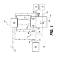
- FIG. 1 illustrates one embodiment of a power take-off (PTO) clutch control system 10 suitable for a vehicle 12, such as a tractor.
- the vehicle 12 typically has a motor or an engine 14 as a drive source, a drive train 16, and a transmission 20 having a PTO clutch.
- the vehicle 12 may also have a torque converter 18.
- the engine 14 is connected to the torque converter 18 via a shaft 22, the torque converter 18 is connected to the transmission 20 via a shaft 24, and the transmission 20 may be connected to the vehicle drive train 16.
- the PTO clutch is engageable with the engine 14 via, for example, an input shaft 24, and in turn, directly engages an implement 19 via a PTO output shaft 26.
- the PTO clutch control system 10 is utilized with a PTO clutch 28, which may be, for example, a hydraulic actuated clutch.
- the transmission 20 can be shifted or switched by selectively engaging and disengaging the PTO clutch 28.
- the PTO clutch 28 is selectively engaged and disengaged by pressure control valve 32.
- the pressure control valve 32 is actuated by a solenoid.
- the PTO clutch control system 10 also includes a displacement pump coupled to the PTO clutch 28 to supply pressurized hydraulic fluid from a reservoir to the PTO clutch 28 through the pressure control valve 32.
- the system 10 moreover, may have a relief valve to regulate fluid pressure of the hydraulic fluid. (The pump, the reservoir, and the relief valve are not shown in FIG. 1.)
- the PTO clutch control system 10 further includes a control unit 36 coupled to the pressure control valve 32 and an operator switch 38, which produces a PTO input signal.
- the operator of the vehicle 12 manipulates the operator switch 38 to operate the PTO clutch 28 via the control unit 36.
- the control unit 36 Upon receipt of the PTO switch input signal, the control unit 36 sends a command signal to the pressure control valve 32 to responsively control the operation of the pressure control valve 32.
- the control unit 36 may also receive various other input signals that affect PTO clutch operation.
- Such input signals may include an engine speed signal from an engine speed sensor 40, a transmission input speed signal from a PTO transmission input speed sensor 42, a PTO output speed signal from a PTO output speed sensor 44, a temperature signal from a transmission oil temperature sensor 46, and a clutch pressure signal from a PTO clutch pressure sensor 48.
- the sensors may be conventional electrical transducers, such as, for example, potentiometers and/or magnetic speed pickups.
- the control unit 36 may consider the values of the input signals to determine a desired command signal to the control pressure valve 32.
- the control unit 36 needs to compensate the fill time for the PTO clutch 28 according to input signals to achieve high quality operation of the PTO clutch 28.
- the control unit 36 may include a microprocessor with an internal clock and memory, an input/output device, and an array of proportional solenoid current drivers.
- One solenoid driver is dedicated to the pressure control valve 32.
- the control unit 36 delivers the command signal proportional to the desired solenoid current, and the current driver uses a Pulse Width Modulated voltage to produce the desired current.
- the pressure control valve 32 is configured to provide a hydraulic fluid flow to the PTO clutch 28 sufficient to maintain a clutch pressure proportional to the solenoid current.
- the control unit 36 controls the clutch pressure of the PTO clutch 28 by providing the solenoid driver circuit with the command signal proportional to the clutch pressure.
- the control unit 36 includes PTO control logic (PCL).
- PCL PTO control logic
- the PCL monitors the operator controls, such as the operator switch 38, and various other input signals to determine the desired PTO engagement profile.
- the desired PTO engagement profile is then passed to a Clutch Control Logic (CCL) to handle engagement and disengagement of the PTO clutch.
- CCL Clutch Control Logic
- the CCL may generate command signals in units of pressure, such as kPa, and the command signals may be converted into current through a linearization process before being provided the pressure control valve 32.
- the linearization process compensates for many non-linearities and variabilities of the pressure control valve 32, and the conversion of the command signals may be calibrated.
- the command signals are then sent to the pressure control valve to engage and disengage the PTO clutch according to a PTO clutch engagement status requested by the PCL.
- the PCL and CCL may be software programs typically stored in memory, such as read-only memory or random-access memory.
- the PTO clutch control system 10 may utilize a finite state machine model to operate the PTO clutch 28.
- a finite state machine model has a finite number of discrete conditions that must respond to a limited number of events. Each of the possible conditions is designated as a state, and in each state, decisions must be made as to how to respond to each of the possible events.
- the system with the finite state machine model may transition from one state to another state, remain in the present state, or take some action in response to the event.
- FIG. 2 illustrates the relationship between the command signal (current) provided to pressure control valve 32 with respect to each of the finite states during the operation of the PTO clutch control system 10.
- the PTO clutch control system 10 has multiple states, such as idling, filling, holding, modulating, climbing, maxing, sustaining, releasing, retracting, and unlocking. Before torque is transmitted between the engine 14 and the implement 19, a fill time occurs. The fill time is the elapsed time wherein the PTO clutch 28 moves from the released to the engaged position.
- the PTO control system 10 may enter into the modulation state.
- the end-of-fill of the PTO clutch 28 may be predetermined or sensed by various methods. For example, dedicated end-of-fill detection sensors, timing methods, or other known end-of-fill detection methods may be employed to indicate the end-of-fill. Also, clutch-slip may be monitored.
- the PTO clutch 28 is actuated by the pressure control valve 32 to achieve a desired clutch pressure against the off-going PTO clutch.
- the command signal is sent from the control unit 36 to the pressure control valve 32 to gradually increase the clutch pressure of the PTO clutch 28 until the PTO clutch 28 locks up.
- the modulation state may utilize either open-loop or closed-loop control to gradually increase the clutch pressure to cause a desired decrease in clutch slip.
- the command signal to control clutch pressure is modulated at a predetermine rate.
- the command signal is modulated by feeding back values based on a function of some other parameter. The clutch pressure is gradually increased to a maximum pressure level to complete the engagement.
- a vehicle may often be operated under various inertial loads, which adversely affects smooth PTO clutch engagement.
- the PTO clutch may be subject to a widely varying implement inertia.
- a pressure profile that achieves smooth PTO clutch engagement from low to high inertia is required.
- the present invention in contrast to previous PTO clutch systems that are prone to performance degradation depending on the implement loading conditions, utilizes a single predetermined profile that accommodates virtually any implement loading condition exerted on the PTO clutch.
- an exponential function with a single profile may be used to determine the command signal during the modulation state. Consequently, by using the single profile, the operator of the vehicle need not change profiles of the command signal during the operation of the PTO clutch control system, and the PTO clutch 28 can be operated automatically.
- the single profile modulation accommodates a significant range of loads, resulting in smooth engagement of the PTO clutch.
- the single profile of the valve command signal during the modulation state may be generated using the following exemplary exponential functions:
- the single profile may be a piece-wise linear approximation of a non-linear function. By connecting small linear segments or pieces that closely approximate a non-linear function, a single profile of the desired non-linear function can be created.
- FIG. 3 illustrates the relationship between the clutch pressure and time using the above exponential functions with different constants.
- the graphs in FIG. 3 were plotted by using one of the three exponential equations above.
- the graphs were plotted for modulation times of 0.5, 1, 1.5, 2, 2.5, 3, 3.5, 4, 4.5, and 5 seconds.
- the modulation time of 3 seconds was used to plot the graphs.
- a and B can be selected according to a desired top clutch pressure.
- FIG. 4 illustrates an exemplary relationship between clutch pressure and time during modulation.
- FIG. 5 provides various operational parameters for three inertial loading conditions (1, 15, and 30 Nms 2 ).
- the PTO clutch control system 10 is initially in the idling state. In the idling state, the PTO clutch 28 is disengaged and fully retracted. When the operator selects to engage the PTO clutch 28 by actuating the operator switch 38, the PTO clutch control system 10 proceeds to the filling state.
- the PTO clutch 28 In the filling state, the PTO clutch 28 is stroked to remove the clearance between clutch plates and disks.
- the command signal from the control unit 36 to the pressure control valve 32 is typically a pulse, followed by a ramp down to a hold level, at which the PTO clutch 28 is nearly touched up. At the touch-up point, the PTO clutch 28 may not be transmitting torque, but is ready to engage.
- the command signal is ramped up in either an open-loop (at a predetermined rate) or a closed-loop (as a function of some other parameter) until the PTO clutch 28 locks up.
- the command signal may be modulated by a single predetermined profile function to control the clutch slip.
- an open-loop function such as the relationship illustrated in FIG. 4, is used to modulate the command signal.
- the command signal is ramped up to the maximum clutch pressure over a specified period of time to ensure that the PTO clutch 28 is fully locked up. Further, during the maxing state, the PTO clutch 28 continuously maintains the maximum clutch pressure.
- the clutch pressure may be reduced from the maximum and maintained at the reduced clutch pressure.
- the clutch pressure is reduced to improve seal life of the PTO clutch 28.
- the PTO clutch When commanded by the operator, the PTO clutch begins disengagement by moving to the releasing state. In the releasing state, the PTO clutch 28 begins disengagement (unlocking) as the command signal is ramped down to zero pressure. In an exemplary embodiment, the releasing state may include multiple segment ramps.
- the releasing state may be followed by the retracting state. Even though the command signal may be zero, the PTO clutches may not be fully retracted due to delay in clutch response time. For re-engagement (filling) from the retracting state, therefore, it may be necessary to use a different fill profile than for re-engagement from the idling state.
- the unlocking state is similar to the releasing state. Unlike the releasing state, however, the hold level is maintained in the unlocking state. This feature may be used to partially disengage the PTO clutch when an immediate re-engagement is anticipated.
- the present invention provides a system and method that can smoothly and effectively engage a PTO clutch over a wide variety of loads.
- the system and method have application in a wide variety of machines, including, but not limited to, construction and agricultural vehicle.
Landscapes
- Engineering & Computer Science (AREA)
- Mechanical Engineering (AREA)
- Fluid Mechanics (AREA)
- Transportation (AREA)
- Combustion & Propulsion (AREA)
- Life Sciences & Earth Sciences (AREA)
- Physics & Mathematics (AREA)
- Chemical & Material Sciences (AREA)
- General Engineering & Computer Science (AREA)
- Soil Sciences (AREA)
- Environmental Sciences (AREA)
- Hydraulic Clutches, Magnetic Clutches, Fluid Clutches, And Fluid Joints (AREA)
- Arrangement And Driving Of Transmission Devices (AREA)
Abstract
Description
Claims (10)
- A method for controlling a PTO clutch (28) of a transmission (20) being subject to a varying inertial load, comprising:providing a signal to a pressure control valve (32) selectively engaged with the PTO clutch configured to engage a drive source (14) of the transmission with an implement (19); andmodulating the signal to the pressure control valve based on a single predetermined profile.
- The method of claim 1, wherein the single profile is a non-linear function.
- The method of claim 2, wherein the single profile is an exponential function.
- The method of claim 3, wherein the single profile is based on one of the following functions:
- The method of claim 1 wherein the single profile is a piece-wise linear approximation of a non-linear function.
- A power take-off clutch control system (10) for controlling a PTO clutch (28), the system comprising:a pressure control valve (32) to actuate the clutch; anda control unit (36) in communication with the pressure control valve, wherein an input signal to the pressure control valve tracks a single predetermined profile.
- The system of claim 6, wherein the modulation signal is based on a non-linear function.
- The system of claim 7, wherein the modulation signal is based on an exponential function.
- The system of claim 8, wherein the modulation signal is based on one of the following functions:
- The system of claim 6, wherein the profile is a piece-wise linear approximation of a non-linear function.
Applications Claiming Priority (2)
| Application Number | Priority Date | Filing Date | Title |
|---|---|---|---|
| US925529 | 2001-08-10 | ||
| US09/925,529 US6564915B2 (en) | 2001-08-10 | 2001-08-10 | Power take-off clutch control system |
Publications (3)
| Publication Number | Publication Date |
|---|---|
| EP1285806A2 true EP1285806A2 (en) | 2003-02-26 |
| EP1285806A3 EP1285806A3 (en) | 2006-11-02 |
| EP1285806B1 EP1285806B1 (en) | 2009-01-07 |
Family
ID=25451858
Family Applications (1)
| Application Number | Title | Priority Date | Filing Date |
|---|---|---|---|
| EP02013246A Expired - Lifetime EP1285806B1 (en) | 2001-08-10 | 2002-06-17 | Power take-off clutch control system |
Country Status (4)
| Country | Link |
|---|---|
| US (1) | US6564915B2 (en) |
| EP (1) | EP1285806B1 (en) |
| AT (1) | ATE419986T1 (en) |
| DE (1) | DE60230701D1 (en) |
Cited By (5)
| Publication number | Priority date | Publication date | Assignee | Title |
|---|---|---|---|---|
| WO2009085151A1 (en) * | 2007-12-21 | 2009-07-09 | Caterpillar Inc. | Clutch end-of-fill detection strategy related solenoid valve |
| EP2149471A1 (en) * | 2008-07-28 | 2010-02-03 | ZF FRIEDRICHSHAFEN Aktiengesellschaft | Method and assembly for coupling and decoupling an auxiliary drive to an automated gear |
| EP1912842A4 (en) * | 2005-08-03 | 2013-03-27 | Deere & Co | Method of using a pto clutch for auxiliary load measurement |
| WO2018132611A1 (en) * | 2016-01-11 | 2018-07-19 | Cnh Industrial America Llc | Supervisory control system to select pto clutch engagement method based on real-time inertial load estimation |
| SE2350316A1 (en) * | 2023-03-21 | 2024-09-22 | Scania Cv Ab | Method and control arrangement for changing an activation state for a power take-off |
Families Citing this family (9)
| Publication number | Priority date | Publication date | Assignee | Title |
|---|---|---|---|---|
| DE10145588A1 (en) * | 2001-09-15 | 2003-04-24 | Deere & Co | Method and device for controlling a clutch |
| US6935474B2 (en) * | 2003-04-07 | 2005-08-30 | International Truck Intellectual Property Company, Llc | Compressed air actuated clutch interlock for clutched power take off unit |
| US8066619B2 (en) * | 2008-04-19 | 2011-11-29 | Pt Tech, Inc | Clutch control system |
| US8489297B2 (en) * | 2009-04-15 | 2013-07-16 | Caterpillar Inc. | Clutch hold level as a function of torque |
| US8066620B2 (en) * | 2009-05-19 | 2011-11-29 | GM Global Technology Operations LLC | Method of clutch actuation for hybrid transmissions |
| JP6258784B2 (en) * | 2014-05-27 | 2018-01-10 | ヤンマー株式会社 | Tractor |
| US10449944B2 (en) | 2017-11-01 | 2019-10-22 | Cnh Industrial America Llc | System and method for controlling PTO clutch engagement using adaptive incremental PID control |
| US11326655B2 (en) | 2018-12-11 | 2022-05-10 | Vermeer Manufacturing Company | Material reduction machine with drivetrain protection system |
| DE102020215661B4 (en) * | 2020-12-10 | 2023-06-01 | Zf Friedrichshafen Ag | Method for operating a motor vehicle with power take-off |
Family Cites Families (22)
| Publication number | Priority date | Publication date | Assignee | Title |
|---|---|---|---|---|
| US3237404A (en) * | 1965-05-03 | 1966-03-01 | Gen Motors Corp | Re-expansion gas turbine engine with power transfer between turbines |
| US3851463A (en) * | 1972-07-21 | 1974-12-03 | Gen Motors Corp | Gas turbine engine power shift transmission power train |
| DE3048573A1 (en) * | 1980-12-22 | 1982-09-09 | Mannesmann Rexroth GmbH, 8770 Lohr | Working cylinder actuator system - has back pressure valve between control valve and accumulator or cylinder |
| GB8408841D0 (en) * | 1984-04-05 | 1984-05-16 | Massey Ferguson Services Nv | Clutch engagement control system |
| US5053960A (en) | 1987-05-29 | 1991-10-01 | J. I. Case Company | Electronic control system for powershift transmission with compensation for variation in supply voltage |
| DE4215583A1 (en) * | 1992-05-12 | 1993-11-18 | Bosch Gmbh Robert | Method for engaging the PTO on a commercial vehicle by means of a mechanical clutch |
| JP2806462B2 (en) * | 1992-07-03 | 1998-09-30 | 株式会社クボタ | Work vehicle traveling speed change structure |
| US5467854A (en) | 1994-06-07 | 1995-11-21 | Caterpillar Inc. | Method of controlling clutch-to-clutch shifts for a powershift transmission |
| US5494142A (en) | 1994-08-01 | 1996-02-27 | Case Corporation | Power take off clutch engagement control system |
| JP3861321B2 (en) | 1996-05-02 | 2006-12-20 | トヨタ自動車株式会社 | Hybrid car |
| GB9623784D0 (en) * | 1996-11-15 | 1997-01-08 | Massey Ferguson Sa | PTQ shaft monitoring & control system |
| US6070538A (en) * | 1996-11-22 | 2000-06-06 | Case Corporation | Modular agricultural implement control system |
| US6206803B1 (en) | 1997-04-16 | 2001-03-27 | Tranmissiones Tsp, S.A. De C.V. | Method and apparatus for operating a clutch in an automated mechanical transmission |
| JPH1193980A (en) * | 1997-09-19 | 1999-04-06 | Kubota Corp | Work vehicle |
| US6092021A (en) | 1997-12-01 | 2000-07-18 | Freightliner Corporation | Fuel use efficiency system for a vehicle for assisting the driver to improve fuel economy |
| US6119072A (en) | 1998-01-15 | 2000-09-12 | Deere & Company | Calibration method for transmission control clutches |
| US6186925B1 (en) | 1998-11-13 | 2001-02-13 | Cummins Engine Company, Inc. | System for protecting drive train components from excessive engine inertial forces |
| US6151543A (en) | 1999-01-14 | 2000-11-21 | Case Corporation | Method and apparatus for skip shifting in a power transmission |
| US6022292A (en) | 1999-02-12 | 2000-02-08 | Deere & Company | Method of adjusting an engine load signal used by a transmission controller |
| US6151975A (en) | 1999-03-25 | 2000-11-28 | Dana Corporation | Power take-off unit housing having integral hydraulic manifold |
| US6193630B1 (en) * | 1999-07-26 | 2001-02-27 | Deere & Company | Slip-based shift control system |
| US6165102A (en) | 1999-11-22 | 2000-12-26 | Cummins Engine Company, Inc. | System for controlling output torque characteristics of an internal combustion engine |
-
2001
- 2001-08-10 US US09/925,529 patent/US6564915B2/en not_active Expired - Lifetime
-
2002
- 2002-06-17 EP EP02013246A patent/EP1285806B1/en not_active Expired - Lifetime
- 2002-06-17 DE DE60230701T patent/DE60230701D1/en not_active Expired - Lifetime
- 2002-06-17 AT AT02013246T patent/ATE419986T1/en not_active IP Right Cessation
Cited By (10)
| Publication number | Priority date | Publication date | Assignee | Title |
|---|---|---|---|---|
| EP1912842A4 (en) * | 2005-08-03 | 2013-03-27 | Deere & Co | Method of using a pto clutch for auxiliary load measurement |
| WO2009085151A1 (en) * | 2007-12-21 | 2009-07-09 | Caterpillar Inc. | Clutch end-of-fill detection strategy related solenoid valve |
| CN101903663A (en) * | 2007-12-21 | 2010-12-01 | 卡特彼勒公司 | Solenoid associated with clutch fill completion detection strategy |
| US7909733B2 (en) | 2007-12-21 | 2011-03-22 | Caterpillar Inc. | Clutch end-of-fill detection strategy |
| EP2149471A1 (en) * | 2008-07-28 | 2010-02-03 | ZF FRIEDRICHSHAFEN Aktiengesellschaft | Method and assembly for coupling and decoupling an auxiliary drive to an automated gear |
| WO2018132611A1 (en) * | 2016-01-11 | 2018-07-19 | Cnh Industrial America Llc | Supervisory control system to select pto clutch engagement method based on real-time inertial load estimation |
| US10443523B2 (en) | 2016-01-11 | 2019-10-15 | Cnh Industrial America Llc | Supervisory control system to select PTO clutch engagement method based on real-time inertial load estimation |
| SE2350316A1 (en) * | 2023-03-21 | 2024-09-22 | Scania Cv Ab | Method and control arrangement for changing an activation state for a power take-off |
| SE546836C2 (en) * | 2023-03-21 | 2025-02-25 | Scania Cv Ab | Method and control arrangement for changing an activation state for a power take-off |
| US12358486B2 (en) | 2023-03-21 | 2025-07-15 | Scania Cv Ab | Method and control arrangement for changing an activation state for a power take-off |
Also Published As
| Publication number | Publication date |
|---|---|
| US20030029691A1 (en) | 2003-02-13 |
| ATE419986T1 (en) | 2009-01-15 |
| EP1285806B1 (en) | 2009-01-07 |
| EP1285806A3 (en) | 2006-11-02 |
| DE60230701D1 (en) | 2009-02-26 |
| US6564915B2 (en) | 2003-05-20 |
Similar Documents
| Publication | Publication Date | Title |
|---|---|---|
| US6564915B2 (en) | Power take-off clutch control system | |
| US6267189B1 (en) | Power take-off engagement control system | |
| US5737979A (en) | Method of calibrating clutches in a transmission | |
| US7048106B2 (en) | Power take-off control system and method | |
| CA1306530C (en) | Steady state slip detection/correction for a motor vehicle transmission | |
| US4526255A (en) | Fluid drive transmission employing lockup clutch | |
| CN106494403B (en) | System and method for regulating wheel slip in a towing vehicle | |
| AU637024B2 (en) | An electrohydraulic control device for a drive train of a vehicle | |
| US5224577A (en) | Calibration method for transmission control clutches | |
| US5549185A (en) | Power take off torque limiting control system | |
| US5249658A (en) | Transmission controller | |
| US6295497B1 (en) | Method and apparatus for adaptively shifting ranges in a continuously variable transmission | |
| US5082097A (en) | Transmission controller | |
| JPH0868458A (en) | Power shift transmission control method | |
| US5494142A (en) | Power take off clutch engagement control system | |
| WO2012087448A1 (en) | Clutch calibration for continuously variable transmission | |
| US6086509A (en) | Method and apparatus for transmission clutch modulation during gear shift based on payload and selected direction | |
| US6193630B1 (en) | Slip-based shift control system | |
| US5950789A (en) | End of fill detector for a fluid actuated clutch | |
| US6216074B1 (en) | Method for determining the fill time of a transmission clutch | |
| US20040014563A1 (en) | Transmission shift control with engine torque control | |
| US7234366B2 (en) | Power take-off control system | |
| US20060219509A1 (en) | System and method for controlling engagement of a clutch | |
| US8825323B2 (en) | Machine control system implementing speed-based clutch modulation | |
| EP1580063B1 (en) | Power take-off control system. |
Legal Events
| Date | Code | Title | Description |
|---|---|---|---|
| PUAI | Public reference made under article 153(3) epc to a published international application that has entered the european phase |
Free format text: ORIGINAL CODE: 0009012 |
|
| AK | Designated contracting states |
Designated state(s): AT BE CH CY DE DK ES FI FR GB GR IE IT LI LU MC NL PT SE TR Kind code of ref document: A2 Designated state(s): AT BE CH CY DE DK ES FI FR GB GR IE IT LI LU MC NL PT SE TR |
|
| AX | Request for extension of the european patent |
Extension state: AL LT LV MK RO SI |
|
| PUAL | Search report despatched |
Free format text: ORIGINAL CODE: 0009013 |
|
| AK | Designated contracting states |
Kind code of ref document: A3 Designated state(s): AT BE CH CY DE DK ES FI FR GB GR IE IT LI LU MC NL PT SE TR |
|
| AX | Request for extension of the european patent |
Extension state: AL LT LV MK RO SI |
|
| RIC1 | Information provided on ipc code assigned before grant |
Ipc: B60K 25/06 20060101ALI20060928BHEP Ipc: B60K 17/28 20060101AFI20021121BHEP |
|
| 17P | Request for examination filed |
Effective date: 20070502 |
|
| AKX | Designation fees paid |
Designated state(s): AT BE CH CY DE DK ES FI FR GB GR IE IT LI LU MC NL PT SE TR |
|
| 17Q | First examination report despatched |
Effective date: 20070806 |
|
| GRAP | Despatch of communication of intention to grant a patent |
Free format text: ORIGINAL CODE: EPIDOSNIGR1 |
|
| GRAS | Grant fee paid |
Free format text: ORIGINAL CODE: EPIDOSNIGR3 |
|
| GRAA | (expected) grant |
Free format text: ORIGINAL CODE: 0009210 |
|
| AK | Designated contracting states |
Kind code of ref document: B1 Designated state(s): AT BE CH CY DE DK ES FI FR GB GR IE IT LI LU MC NL PT SE TR |
|
| REG | Reference to a national code |
Ref country code: GB Ref legal event code: FG4D |
|
| REG | Reference to a national code |
Ref country code: CH Ref legal event code: EP |
|
| REG | Reference to a national code |
Ref country code: IE Ref legal event code: FG4D |
|
| REF | Corresponds to: |
Ref document number: 60230701 Country of ref document: DE Date of ref document: 20090226 Kind code of ref document: P |
|
| PG25 | Lapsed in a contracting state [announced via postgrant information from national office to epo] |
Ref country code: NL Free format text: LAPSE BECAUSE OF FAILURE TO SUBMIT A TRANSLATION OF THE DESCRIPTION OR TO PAY THE FEE WITHIN THE PRESCRIBED TIME-LIMIT Effective date: 20090107 |
|
| NLV1 | Nl: lapsed or annulled due to failure to fulfill the requirements of art. 29p and 29m of the patents act | ||
| PG25 | Lapsed in a contracting state [announced via postgrant information from national office to epo] |
Ref country code: ES Free format text: LAPSE BECAUSE OF FAILURE TO SUBMIT A TRANSLATION OF THE DESCRIPTION OR TO PAY THE FEE WITHIN THE PRESCRIBED TIME-LIMIT Effective date: 20090418 Ref country code: FI Free format text: LAPSE BECAUSE OF FAILURE TO SUBMIT A TRANSLATION OF THE DESCRIPTION OR TO PAY THE FEE WITHIN THE PRESCRIBED TIME-LIMIT Effective date: 20090107 |
|
| PG25 | Lapsed in a contracting state [announced via postgrant information from national office to epo] |
Ref country code: SE Free format text: LAPSE BECAUSE OF FAILURE TO SUBMIT A TRANSLATION OF THE DESCRIPTION OR TO PAY THE FEE WITHIN THE PRESCRIBED TIME-LIMIT Effective date: 20090407 Ref country code: AT Free format text: LAPSE BECAUSE OF FAILURE TO SUBMIT A TRANSLATION OF THE DESCRIPTION OR TO PAY THE FEE WITHIN THE PRESCRIBED TIME-LIMIT Effective date: 20090107 Ref country code: PT Free format text: LAPSE BECAUSE OF FAILURE TO SUBMIT A TRANSLATION OF THE DESCRIPTION OR TO PAY THE FEE WITHIN THE PRESCRIBED TIME-LIMIT Effective date: 20090608 |
|
| PG25 | Lapsed in a contracting state [announced via postgrant information from national office to epo] |
Ref country code: BE Free format text: LAPSE BECAUSE OF FAILURE TO SUBMIT A TRANSLATION OF THE DESCRIPTION OR TO PAY THE FEE WITHIN THE PRESCRIBED TIME-LIMIT Effective date: 20090107 |
|
| PG25 | Lapsed in a contracting state [announced via postgrant information from national office to epo] |
Ref country code: DK Free format text: LAPSE BECAUSE OF FAILURE TO SUBMIT A TRANSLATION OF THE DESCRIPTION OR TO PAY THE FEE WITHIN THE PRESCRIBED TIME-LIMIT Effective date: 20090107 |
|
| PLBE | No opposition filed within time limit |
Free format text: ORIGINAL CODE: 0009261 |
|
| STAA | Information on the status of an ep patent application or granted ep patent |
Free format text: STATUS: NO OPPOSITION FILED WITHIN TIME LIMIT |
|
| 26N | No opposition filed |
Effective date: 20091008 |
|
| PG25 | Lapsed in a contracting state [announced via postgrant information from national office to epo] |
Ref country code: MC Free format text: LAPSE BECAUSE OF NON-PAYMENT OF DUE FEES Effective date: 20090630 |
|
| REG | Reference to a national code |
Ref country code: CH Ref legal event code: PL |
|
| GBPC | Gb: european patent ceased through non-payment of renewal fee |
Effective date: 20090617 |
|
| REG | Reference to a national code |
Ref country code: FR Ref legal event code: ST Effective date: 20100226 |
|
| REG | Reference to a national code |
Ref country code: IE Ref legal event code: MM4A |
|
| PG25 | Lapsed in a contracting state [announced via postgrant information from national office to epo] |
Ref country code: CH Free format text: LAPSE BECAUSE OF NON-PAYMENT OF DUE FEES Effective date: 20090630 Ref country code: IE Free format text: LAPSE BECAUSE OF NON-PAYMENT OF DUE FEES Effective date: 20090617 Ref country code: LI Free format text: LAPSE BECAUSE OF NON-PAYMENT OF DUE FEES Effective date: 20090630 Ref country code: FR Free format text: LAPSE BECAUSE OF NON-PAYMENT OF DUE FEES Effective date: 20090630 |
|
| PG25 | Lapsed in a contracting state [announced via postgrant information from national office to epo] |
Ref country code: GB Free format text: LAPSE BECAUSE OF NON-PAYMENT OF DUE FEES Effective date: 20090617 |
|
| PG25 | Lapsed in a contracting state [announced via postgrant information from national office to epo] |
Ref country code: GR Free format text: LAPSE BECAUSE OF FAILURE TO SUBMIT A TRANSLATION OF THE DESCRIPTION OR TO PAY THE FEE WITHIN THE PRESCRIBED TIME-LIMIT Effective date: 20090408 |
|
| PG25 | Lapsed in a contracting state [announced via postgrant information from national office to epo] |
Ref country code: IT Free format text: LAPSE BECAUSE OF FAILURE TO SUBMIT A TRANSLATION OF THE DESCRIPTION OR TO PAY THE FEE WITHIN THE PRESCRIBED TIME-LIMIT Effective date: 20090107 |
|
| PG25 | Lapsed in a contracting state [announced via postgrant information from national office to epo] |
Ref country code: LU Free format text: LAPSE BECAUSE OF NON-PAYMENT OF DUE FEES Effective date: 20090617 |
|
| PG25 | Lapsed in a contracting state [announced via postgrant information from national office to epo] |
Ref country code: TR Free format text: LAPSE BECAUSE OF FAILURE TO SUBMIT A TRANSLATION OF THE DESCRIPTION OR TO PAY THE FEE WITHIN THE PRESCRIBED TIME-LIMIT Effective date: 20090107 |
|
| PG25 | Lapsed in a contracting state [announced via postgrant information from national office to epo] |
Ref country code: CY Free format text: LAPSE BECAUSE OF FAILURE TO SUBMIT A TRANSLATION OF THE DESCRIPTION OR TO PAY THE FEE WITHIN THE PRESCRIBED TIME-LIMIT Effective date: 20090107 |
|
| PGFP | Annual fee paid to national office [announced via postgrant information from national office to epo] |
Ref country code: DE Payment date: 20120629 Year of fee payment: 11 |
|
| REG | Reference to a national code |
Ref country code: DE Ref legal event code: R119 Ref document number: 60230701 Country of ref document: DE Effective date: 20140101 |
|
| PG25 | Lapsed in a contracting state [announced via postgrant information from national office to epo] |
Ref country code: DE Free format text: LAPSE BECAUSE OF NON-PAYMENT OF DUE FEES Effective date: 20140101 |