EP1285719B1 - Method for making wear-resistant surface layers using laser - Google Patents
Method for making wear-resistant surface layers using laser Download PDFInfo
- Publication number
- EP1285719B1 EP1285719B1 EP02016943A EP02016943A EP1285719B1 EP 1285719 B1 EP1285719 B1 EP 1285719B1 EP 02016943 A EP02016943 A EP 02016943A EP 02016943 A EP02016943 A EP 02016943A EP 1285719 B1 EP1285719 B1 EP 1285719B1
- Authority
- EP
- European Patent Office
- Prior art keywords
- inductor
- cycle
- laser
- preheat
- temperature
- Prior art date
- Legal status (The legal status is an assumption and is not a legal conclusion. Google has not performed a legal analysis and makes no representation as to the accuracy of the status listed.)
- Expired - Lifetime
Links
Images


Classifications
-
- F—MECHANICAL ENGINEERING; LIGHTING; HEATING; WEAPONS; BLASTING
- F15—FLUID-PRESSURE ACTUATORS; HYDRAULICS OR PNEUMATICS IN GENERAL
- F15B—SYSTEMS ACTING BY MEANS OF FLUIDS IN GENERAL; FLUID-PRESSURE ACTUATORS, e.g. SERVOMOTORS; DETAILS OF FLUID-PRESSURE SYSTEMS, NOT OTHERWISE PROVIDED FOR
- F15B15/00—Fluid-actuated devices for displacing a member from one position to another; Gearing associated therewith
- F15B15/08—Characterised by the construction of the motor unit
- F15B15/14—Characterised by the construction of the motor unit of the straight-cylinder type
- F15B15/1423—Component parts; Constructional details
- F15B15/1457—Piston rods
-
- B—PERFORMING OPERATIONS; TRANSPORTING
- B23—MACHINE TOOLS; METAL-WORKING NOT OTHERWISE PROVIDED FOR
- B23K—SOLDERING OR UNSOLDERING; WELDING; CLADDING OR PLATING BY SOLDERING OR WELDING; CUTTING BY APPLYING HEAT LOCALLY, e.g. FLAME CUTTING; WORKING BY LASER BEAM
- B23K10/00—Welding or cutting by means of a plasma
- B23K10/02—Plasma welding
- B23K10/027—Welding for purposes other than joining, e.g. build-up welding
-
- B—PERFORMING OPERATIONS; TRANSPORTING
- B23—MACHINE TOOLS; METAL-WORKING NOT OTHERWISE PROVIDED FOR
- B23K—SOLDERING OR UNSOLDERING; WELDING; CLADDING OR PLATING BY SOLDERING OR WELDING; CUTTING BY APPLYING HEAT LOCALLY, e.g. FLAME CUTTING; WORKING BY LASER BEAM
- B23K26/00—Working by laser beam, e.g. welding, cutting or boring
- B23K26/20—Bonding
- B23K26/32—Bonding taking account of the properties of the material involved
-
- B—PERFORMING OPERATIONS; TRANSPORTING
- B23—MACHINE TOOLS; METAL-WORKING NOT OTHERWISE PROVIDED FOR
- B23K—SOLDERING OR UNSOLDERING; WELDING; CLADDING OR PLATING BY SOLDERING OR WELDING; CUTTING BY APPLYING HEAT LOCALLY, e.g. FLAME CUTTING; WORKING BY LASER BEAM
- B23K26/00—Working by laser beam, e.g. welding, cutting or boring
- B23K26/34—Laser welding for purposes other than joining
- B23K26/342—Build-up welding
-
- B—PERFORMING OPERATIONS; TRANSPORTING
- B23—MACHINE TOOLS; METAL-WORKING NOT OTHERWISE PROVIDED FOR
- B23K—SOLDERING OR UNSOLDERING; WELDING; CLADDING OR PLATING BY SOLDERING OR WELDING; CUTTING BY APPLYING HEAT LOCALLY, e.g. FLAME CUTTING; WORKING BY LASER BEAM
- B23K26/00—Working by laser beam, e.g. welding, cutting or boring
- B23K26/60—Preliminary treatment
-
- B—PERFORMING OPERATIONS; TRANSPORTING
- B23—MACHINE TOOLS; METAL-WORKING NOT OTHERWISE PROVIDED FOR
- B23K—SOLDERING OR UNSOLDERING; WELDING; CLADDING OR PLATING BY SOLDERING OR WELDING; CUTTING BY APPLYING HEAT LOCALLY, e.g. FLAME CUTTING; WORKING BY LASER BEAM
- B23K26/00—Working by laser beam, e.g. welding, cutting or boring
- B23K26/70—Auxiliary operations or equipment
-
- B—PERFORMING OPERATIONS; TRANSPORTING
- B23—MACHINE TOOLS; METAL-WORKING NOT OTHERWISE PROVIDED FOR
- B23K—SOLDERING OR UNSOLDERING; WELDING; CLADDING OR PLATING BY SOLDERING OR WELDING; CUTTING BY APPLYING HEAT LOCALLY, e.g. FLAME CUTTING; WORKING BY LASER BEAM
- B23K35/00—Rods, electrodes, materials, or media, for use in soldering, welding, or cutting
- B23K35/02—Rods, electrodes, materials, or media, for use in soldering, welding, or cutting characterised by mechanical features, e.g. shape
- B23K35/0222—Rods, electrodes, materials, or media, for use in soldering, welding, or cutting characterised by mechanical features, e.g. shape for use in soldering, brazing
- B23K35/0244—Powders, particles or spheres; Preforms made therefrom
-
- B—PERFORMING OPERATIONS; TRANSPORTING
- B23—MACHINE TOOLS; METAL-WORKING NOT OTHERWISE PROVIDED FOR
- B23K—SOLDERING OR UNSOLDERING; WELDING; CLADDING OR PLATING BY SOLDERING OR WELDING; CUTTING BY APPLYING HEAT LOCALLY, e.g. FLAME CUTTING; WORKING BY LASER BEAM
- B23K35/00—Rods, electrodes, materials, or media, for use in soldering, welding, or cutting
- B23K35/02—Rods, electrodes, materials, or media, for use in soldering, welding, or cutting characterised by mechanical features, e.g. shape
- B23K35/0255—Rods, electrodes, materials, or media, for use in soldering, welding, or cutting characterised by mechanical features, e.g. shape for use in welding
-
- C—CHEMISTRY; METALLURGY
- C21—METALLURGY OF IRON
- C21D—MODIFYING THE PHYSICAL STRUCTURE OF FERROUS METALS; GENERAL DEVICES FOR HEAT TREATMENT OF FERROUS OR NON-FERROUS METALS OR ALLOYS; MAKING METAL MALLEABLE, e.g. BY DECARBURISATION OR TEMPERING
- C21D1/00—General methods or devices for heat treatment, e.g. annealing, hardening, quenching or tempering
- C21D1/06—Surface hardening
- C21D1/09—Surface hardening by direct application of electrical or wave energy; by particle radiation
-
- C—CHEMISTRY; METALLURGY
- C21—METALLURGY OF IRON
- C21D—MODIFYING THE PHYSICAL STRUCTURE OF FERROUS METALS; GENERAL DEVICES FOR HEAT TREATMENT OF FERROUS OR NON-FERROUS METALS OR ALLOYS; MAKING METAL MALLEABLE, e.g. BY DECARBURISATION OR TEMPERING
- C21D1/00—General methods or devices for heat treatment, e.g. annealing, hardening, quenching or tempering
- C21D1/34—Methods of heating
- C21D1/42—Induction heating
-
- C—CHEMISTRY; METALLURGY
- C21—METALLURGY OF IRON
- C21D—MODIFYING THE PHYSICAL STRUCTURE OF FERROUS METALS; GENERAL DEVICES FOR HEAT TREATMENT OF FERROUS OR NON-FERROUS METALS OR ALLOYS; MAKING METAL MALLEABLE, e.g. BY DECARBURISATION OR TEMPERING
- C21D9/00—Heat treatment, e.g. annealing, hardening, quenching or tempering, adapted for particular articles; Furnaces therefor
- C21D9/50—Heat treatment, e.g. annealing, hardening, quenching or tempering, adapted for particular articles; Furnaces therefor for welded joints
-
- F—MECHANICAL ENGINEERING; LIGHTING; HEATING; WEAPONS; BLASTING
- F15—FLUID-PRESSURE ACTUATORS; HYDRAULICS OR PNEUMATICS IN GENERAL
- F15B—SYSTEMS ACTING BY MEANS OF FLUIDS IN GENERAL; FLUID-PRESSURE ACTUATORS, e.g. SERVOMOTORS; DETAILS OF FLUID-PRESSURE SYSTEMS, NOT OTHERWISE PROVIDED FOR
- F15B15/00—Fluid-actuated devices for displacing a member from one position to another; Gearing associated therewith
- F15B15/08—Characterised by the construction of the motor unit
- F15B15/14—Characterised by the construction of the motor unit of the straight-cylinder type
- F15B15/1423—Component parts; Constructional details
- F15B15/1428—Cylinders
-
- B—PERFORMING OPERATIONS; TRANSPORTING
- B23—MACHINE TOOLS; METAL-WORKING NOT OTHERWISE PROVIDED FOR
- B23K—SOLDERING OR UNSOLDERING; WELDING; CLADDING OR PLATING BY SOLDERING OR WELDING; CUTTING BY APPLYING HEAT LOCALLY, e.g. FLAME CUTTING; WORKING BY LASER BEAM
- B23K2101/00—Articles made by soldering, welding or cutting
- B23K2101/04—Tubular or hollow articles
- B23K2101/06—Tubes
-
- B—PERFORMING OPERATIONS; TRANSPORTING
- B23—MACHINE TOOLS; METAL-WORKING NOT OTHERWISE PROVIDED FOR
- B23K—SOLDERING OR UNSOLDERING; WELDING; CLADDING OR PLATING BY SOLDERING OR WELDING; CUTTING BY APPLYING HEAT LOCALLY, e.g. FLAME CUTTING; WORKING BY LASER BEAM
- B23K2101/00—Articles made by soldering, welding or cutting
- B23K2101/04—Tubular or hollow articles
- B23K2101/14—Heat exchangers
-
- B—PERFORMING OPERATIONS; TRANSPORTING
- B23—MACHINE TOOLS; METAL-WORKING NOT OTHERWISE PROVIDED FOR
- B23K—SOLDERING OR UNSOLDERING; WELDING; CLADDING OR PLATING BY SOLDERING OR WELDING; CUTTING BY APPLYING HEAT LOCALLY, e.g. FLAME CUTTING; WORKING BY LASER BEAM
- B23K2101/00—Articles made by soldering, welding or cutting
- B23K2101/20—Tools
-
- B—PERFORMING OPERATIONS; TRANSPORTING
- B23—MACHINE TOOLS; METAL-WORKING NOT OTHERWISE PROVIDED FOR
- B23K—SOLDERING OR UNSOLDERING; WELDING; CLADDING OR PLATING BY SOLDERING OR WELDING; CUTTING BY APPLYING HEAT LOCALLY, e.g. FLAME CUTTING; WORKING BY LASER BEAM
- B23K2103/00—Materials to be soldered, welded or cut
- B23K2103/02—Iron or ferrous alloys
- B23K2103/04—Steel or steel alloys
-
- B—PERFORMING OPERATIONS; TRANSPORTING
- B23—MACHINE TOOLS; METAL-WORKING NOT OTHERWISE PROVIDED FOR
- B23K—SOLDERING OR UNSOLDERING; WELDING; CLADDING OR PLATING BY SOLDERING OR WELDING; CUTTING BY APPLYING HEAT LOCALLY, e.g. FLAME CUTTING; WORKING BY LASER BEAM
- B23K2103/00—Materials to be soldered, welded or cut
- B23K2103/50—Inorganic material, e.g. metals, not provided for in B23K2103/02 – B23K2103/26
-
- B—PERFORMING OPERATIONS; TRANSPORTING
- B23—MACHINE TOOLS; METAL-WORKING NOT OTHERWISE PROVIDED FOR
- B23K—SOLDERING OR UNSOLDERING; WELDING; CLADDING OR PLATING BY SOLDERING OR WELDING; CUTTING BY APPLYING HEAT LOCALLY, e.g. FLAME CUTTING; WORKING BY LASER BEAM
- B23K35/00—Rods, electrodes, materials, or media, for use in soldering, welding, or cutting
- B23K35/22—Rods, electrodes, materials, or media, for use in soldering, welding, or cutting characterised by the composition or nature of the material
- B23K35/24—Selection of soldering or welding materials proper
- B23K35/32—Selection of soldering or welding materials proper with the principal constituent melting at more than 1550 degrees C
- B23K35/327—Selection of soldering or welding materials proper with the principal constituent melting at more than 1550 degrees C comprising refractory compounds, e.g. carbides
-
- C—CHEMISTRY; METALLURGY
- C21—METALLURGY OF IRON
- C21D—MODIFYING THE PHYSICAL STRUCTURE OF FERROUS METALS; GENERAL DEVICES FOR HEAT TREATMENT OF FERROUS OR NON-FERROUS METALS OR ALLOYS; MAKING METAL MALLEABLE, e.g. BY DECARBURISATION OR TEMPERING
- C21D1/00—General methods or devices for heat treatment, e.g. annealing, hardening, quenching or tempering
- C21D1/06—Surface hardening
- C21D1/09—Surface hardening by direct application of electrical or wave energy; by particle radiation
- C21D1/10—Surface hardening by direct application of electrical or wave energy; by particle radiation by electric induction
-
- F—MECHANICAL ENGINEERING; LIGHTING; HEATING; WEAPONS; BLASTING
- F28—HEAT EXCHANGE IN GENERAL
- F28F—DETAILS OF HEAT-EXCHANGE AND HEAT-TRANSFER APPARATUS, OF GENERAL APPLICATION
- F28F19/00—Preventing the formation of deposits or corrosion, e.g. by using filters or scrapers
- F28F19/02—Preventing the formation of deposits or corrosion, e.g. by using filters or scrapers by using coatings, e.g. vitreous or enamel coatings
- F28F19/06—Preventing the formation of deposits or corrosion, e.g. by using filters or scrapers by using coatings, e.g. vitreous or enamel coatings of metal
-
- Y—GENERAL TAGGING OF NEW TECHNOLOGICAL DEVELOPMENTS; GENERAL TAGGING OF CROSS-SECTIONAL TECHNOLOGIES SPANNING OVER SEVERAL SECTIONS OF THE IPC; TECHNICAL SUBJECTS COVERED BY FORMER USPC CROSS-REFERENCE ART COLLECTIONS [XRACs] AND DIGESTS
- Y02—TECHNOLOGIES OR APPLICATIONS FOR MITIGATION OR ADAPTATION AGAINST CLIMATE CHANGE
- Y02P—CLIMATE CHANGE MITIGATION TECHNOLOGIES IN THE PRODUCTION OR PROCESSING OF GOODS
- Y02P10/00—Technologies related to metal processing
- Y02P10/25—Process efficiency
Definitions
- the invention relates to a method for the effective production of highly wear-resistant Layers on inductively heatable workpieces.
- Objects where their application is possible and is expedient are a variety of abrasive, corrosive, adhesive or sliding wear Components, preferably made of steel, but also made of cast iron or aluminum or titanium alloys.
- the invention is particularly advantageous for all hardenable or crack-sensitive Steels such as B. tempered steels, tool steels, cold work steels, roller bearing steels and hardenable cast iron grades applicable.
- Components for which this invention can be used are e.g. B .: Engine components, pump shafts, heat exchangers and heat exchanger tubes, forming tools, Components of the oil production industry, camshafts, cam levers, valves, etc.
- the reason for this deficiency is that the specific energy supply costs for the laser are significantly higher than for other conventional energy sources such as. B. the TIG or plasma torch.
- a second deficiency is that the layers produced by laser cladding tend to crack rather than those produced by conventional methods when the process changes to harder and therefore less ductile coating materials or martensitic substrate materials.
- Yoshiwara and Kawanami claim ["Method for surface-alloying metal with a high density energy beam and an alloy steel ", EP 0190378A1] a process in which a with a Laser beam focusing unit permanently connected inductor or an oxygen-acetylene burner in Act the feed direction in front of the laser-irradiated area on the workpiece.
- the so preheated area is larger than the subsequently laser-irradiated area.
- the result is accordingly an unsteady preheating temperature field with a maximum that is somewhat towards Laser beam is shifted and runs ahead of the laser-generated temperature field.
- the same arrangement can also be arranged behind the laser beam spot and thus realize reheating.
- the amount of energy generated by the second energy source delivered should be a substantial part of the total process energy required, however remain smaller than the amount of energy provided by the laser beam.
- the in EP 0190378A1 The arrangement described can preferably be used for very large workpieces. It succeeded in using an oxygen-acetylene burner (data for one inductive preheating are not specified) in the surface layer of the substrate material 17Cr2W1Ni (tool steel; chemical composition: 1.74% C; 17.4% Cr; 1.78% W; 0.92% Ni; Rest Fe) at a peak temperature of the preheating cycle of 700 ° C without cracks the same PS claimed alloy. The feed rate reached was 75% higher than the speed achieved without preheating (2.4 m / min at 10 kW Laser power).
- the lack of the method is that the feed rate is not as great can be increased, as is actually the case from estimates of the energy balance should be possible.
- the reason for this results from the fact that with an inductor (lower Energy transfer effectiveness by using the inductive outer field) or with a Oxygen-acetylene burners in the claimed arrangement can generate temperature fields not sufficient enough to meet the requirements of laser alloying or laser cladding can be customized.
- Moves the additional energy source which is about the introduces the same energy as the laser beam, but has a much lower power density, in advance and at the same feed rate as the laser beam, none can optimal maximum temperature can be reached.
- the temperature of the preheating temperature field fell so far at the time of passing the laser beam that can have no significant effect in terms of increasing the feed rate.
- a higher preheating temperature affects the quality of the alloyed Layer that oxide inclusions or pores arise, which the mechanical strength of the Reduce layers and their wear resistance.
- attempts to solve this problem by deoxidizing the coating material Elements and slag formers are added.
- stochastic melt bath turbulence it cannot be ensured that all slag particles or metal oxides up to the Rise the melt pool surface. This means that these coatings are not suitable for loads which experience very high surface pressures or cyclic tensions.
- the aim of the invention is to refine a new type of preheating process for the surface layer Specify especially for laser edge layer finishing, with the significantly higher feed speeds while avoiding cracks in the layer or the substrate material also when used on crack-sensitive substrate materials such.
- the invention has for its object a temperature control for preheating Surface layer refinement and in particular in the case of laser beam surface layer refinement and means for its Realization indicate that allow, at least very briefly and immediately before Finishing process higher preheating temperatures without scaling of the components reach, whereby for larger functional areas the temperature field is not homogeneous over the entire functional area may be kept for the entire duration of the finishing process, the cooling rate in the crack-critical temperature range is independent or almost set regardless of the peak temperature and the generation of the temperature field can be integrated into the process.
- the means of production should also be so flexible can be designed so that the necessary temperature field is also relatively simple on more complex shaped Components can be generated.
- this object is achieved with a method for producing wear-resistant Edge layers by means of an inductively supported laser beam treatment on inductive heatable workpieces as shown in claim 1 solved.
- Advantageous configurations are shown in subclaims 2 to 27.
- Claim 2 specifies a simple arrangement of how the temperature field according to the invention can be generated with the aid of two separate inductors.
- Claims 3 and 4 make advantageous use of the fact that the penetration depth of the inductive field and thus also the depth to which inductive heat is generated decreases with the induction frequency. This can be used to reduce the heating depth of the preheating cycle V 2 to the extent necessary for increasing the speed of the laser processing process.
- the two inductors I 1 and I 2 can also be arranged spatially separate from one another. So z. B.
- the inductor I 1 in a separate preheating station can heat up the component in the preheating cycle V 1 completely or almost completely in parallel with the laser beam treatment, while the inductor I 2 z. B. can be physically connected to the laser beam processing head and generates the preheating cycle V 2 in advance of the laser beam.
- both preheating cycles V 1 and V 2 can also be generated by a single, appropriately designed inductor I G , as stated in claims 5 and 6.
- This approach is particularly economical from an economic point of view because only one induction generator is required.
- Further variants of how the temperature field according to the invention can advantageously be generated with only one inductor are described in claims 7 to 11. Claim 7 makes use of the fact that the amount of heat entered increases with the duration of action with constant coupling conditions.
- the preheating cycles V 1 and V 2 according to the invention and their superposition can be generated by an oscillating movement of the inductor with a correspondingly selected movement function.
- the preheating cycles according to claims 8 to 11 are implemented, in particular, for larger flat or rotationally symmetrical components, the functional surfaces of which are so wide that they have to be treated by scanning in lanes.
- the pulsating temperature increases ⁇ T 1n * in the preheating cycle come about as a result of the fact that each location on the component to be treated is repeatedly run over by means of the inductor I 12b , which is firmly connected to the laser processing head and whose zone of influence across the feed direction is greater than the track distance a, and that entire arrangement after applying a track is shifted by the desired track spacing a.
- the peak temperature of the preheating cycle T 1max is pulsed.
- the stronger and faster temperature increase ⁇ T 2 * in the preheating cycle V 2 can e.g. B. can be achieved by a more intense energy coupling through the inductor part located directly in front of the laser beam impact point L p .
- the idea of the invention is not limited to the fact that the energy input for generating the preheating cycle V 2 must be inductive. Without violating the inventive concept, one or more suitably arranged high-power diode lasers can also be used for this, as noted in claim 13.
- Claim 14 takes advantage of the knowledge that oxidation to the extent specified is not detrimental to the laser processing process and the resulting tribological and mechanical properties, and furthermore improves the absorption of the laser energy. As experiments have shown, sufficient to prevent further oxidation u. U. the sole inert gas shielding of the preheating zone of the preheating cycle V 2 .
- the method according to the invention is not based on the laser cladding described in the prior art or laser alloys limited. As stated in claims 17 to 19, it can be equally advantageous for laser remelting, laser soldering and with additional Means for setting and maintaining special process gas mixtures also for laser gas alloys are used.
- Claim 19 makes advantageous use of this by the preheating process is applied to a laser soldering process.
- a reheating cycle N 1 can also be connected to the laser process cycle L for particularly crack-sensitive materials.
- This post-heating cycle N 1 is preferably also generated by inductive heat supply, as stated in claim 21.
- Economically particularly economical solutions result from claim 22 if the inductor I 3 is designed such that both the preheating cycles V 1 and V 2 and the post-heating cycle N can be realized with this single inductor.
- the inductors set out in claims 5, 6, 7 and 10 can be modified accordingly.
- Claim 23 makes advantageous use of the knowledge that the martensitic zones which arise in the case of hardenable steels under the build-up welded, alloyed, brazed or remelted layer do not have to be crack-triggering with an adapted inductive heat management.
- the martensitic solid conversion zone can thus be integrated as a support layer in the layer structure, as a result of which the layer thicknesses of the welded-on, alloyed or remelted layer can advantageously be selected to be smaller and the feed rates can thereby be increased further.
- wear-resistant martensitic surface layers can be created very effectively next to the overlay welded alloyed or remelted layers.
- Claim 24 makes use of this in an advantageous manner by using a plasma torch instead of a laser as an energy source for the process cycle L without violating the inventive concept. This solution is particularly advantageous when large-area coatings with reduced requirements for layer quality and mixing are to be implemented in a very economical manner.
- the filler material required for alloying or coating is supplied as a powder.
- the claims 25 and 26 take advantage of the new finding that at the high feed speeds achievable according to the invention wires or tapes a lot can be fed more favorably to the weld pool. Because of the high preheating temperature it is no longer necessary to preheat the filler material with the laser beam, as with normal blowing of the powder into the laser beam is achieved. On the other hand, the negative effect avoided that during normal laser gun deposition welding and laser alloying the degree of utilization of the usually very expensive powdered filler materials increasing feed rate decreases.
- FIG. 1 the arrangement for inductively supported laser cladding the lateral surfaces of shafts subject to wear
- FIG. 2 the invention Temperature control for crack-free laser deposition welding at very high Feed speeds
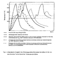
- Fig. 3 a schematic comparison of the invention Temperature-time cycle with those known from the prior art
- Fig. 4 the Arrangement for inductively supported laser cladding of the wear surfaces of special steam generator tubes
- a newly designed shaft cannot withstand the required abrasive wear despite the use of a very wear-resistant steel and surface hardening.
- a shaft made of 42 CrMo4 steel and partial laser cladding of a very wear-resistant coating material should be used.
- this coating system consists of relatively coarse, angular, not remelted WSC with an average diameter of 70 ⁇ m, embedded in a finely dispersed structure made of the matrix material.
- the very high abrasion wear resistance of this cladding material is known from wear experiments.
- the shaft has a diameter of 45 mm and is available in a tempered condition. It will be one Layer thickness after grinding of 0.8 mm is aimed for.
- Laser cladding takes place with the following parameters: laser beam power 5.0 kW, Feed speed 500 mm / min, beam defocusing 29 mm. It leads to a caterpillar width of 5 mm with a track height of 1.2 mm. To make the surface as flat as possible to come, a track spacing of 2.5 mm is selected, which means a degree of overlap of Corresponds to 50%.
- the powder delivery rate is 0.5 kg / h with an estimated powder utilization of 80%.
- the normal laser cladding is not suitable, this relatively brittle coating system to be applied without cracks on the selected tempering steel. Many cross cracks form, that spread from track to track and eventually run through the entire surface.
- the cause of the cracking is that the shrinkage stresses that occur during cooling arise in the layer due to the very large radial temperature gradients the low ductility of the coating system cannot be broken down plastically and therefore exceed the cracking stress in a critical temperature range.
- the Exceeding this critical voltage is caused by the during cooling in the The heat-affected zone of the wave supports the formation of martensite, since the formation during the Martensite formation in the heat affected zone creates compressive stresses to the lateral Strains along the surface cause additional tensile stress on the coating be transmitted.
- the task of the method according to the invention must therefore be without adverse influence of laser deposition welding the temperature gradients and To be able to lower temperature change speeds so far that the critical cracking stress is no longer reached.
- a second disadvantage is the slow feed rate associated with laser cladding, which makes the process uneconomical since in the case of the wave mentioned above the total area to be coated is quite large compared to the volume of the component.
- the object of the method according to the invention is therefore to divide the work into energies in this way to realize that the laser beam only the specific functions of melting powder and of the partial melting of the surface of the wave for the purpose of adhesion, while the preheating that requires a lot of energy to the required depth through the inductive Preheating source is applied.
- FIG. 1 shows schematically the arrangement according to the invention implemented for this purpose (FIG. 1a) and the temperature control according to the invention (Fig. 1 b) shown.
- the invention Temperature control is also given more precisely and with all the necessary reference symbols explained in Fig. 2.
- the shaft (18) is to be coated with the multi-component coating material described above.
- the main components of the arrangement consist of a CO 2 laser (1), an induction generator (2), a CNC control (3), a motion machine (4), the powder feed device (5) and the inductors (8) and (11) ,
- the laser beam (13) is directed onto the workpiece (18) by the deflecting mirror (14) and focused by the laser beam shaping system (15).
- the deflection mirror is reflective for the 10.6 ⁇ m wavelength of the CO 2 laser and transparent for the 1 ⁇ m wavelength range.
- the temperature of the laser process zone (17) can be checked and regulated by the pyrometer (7).
- the inductor I G consists of the two inductor parts I 1 (11) and I 2 (8), which each generate the preheating cycle V 1 and V 2 . It is a five-turn ring inductor, the first 4 turns forming the inductor part I 1 (11) and the fifth turn the inductor part I 2 (8).
- the coupling distance for the inductor part (11) is chosen to be 5 mm. This coupling distance guarantees a gentle coupling with sufficient homogeneity of the inductive field at the selected winding distance of about 4 mm.
- the coupling distance for the inductor part I 2 (8) is reduced to 2 mm and surrounded with magnetic field reinforcement plates (12) acting as magnetic field concentrators.
- the distance between the laser beam impact point (17) and the edge of the magnetic field reinforcement plates is 7 mm.
- the inductor I G (8 + 11) is surrounded by a protective gas cover (10).
- An inert gas is admitted via the protective gas inlet (9) and escapes from the protective gas outlets (20) and (21) at low speed. This ensures adequate oxygen exclusion.
- the pyrometer (6) monitors the maximum temperature T 1max of the preheating cycle V 1 by means of the CNC (3) over a transparent area in the protective gas cover (10).
- the two starting powders are fed through the powder conveyor (5) via the powder nozzle (16) Laser process zone (17) brought.
- the powder feed nozzle (16) is dragging under one Angle of 45 ° to the laser beam axis aimed at the center of the laser process zone (17).
- the Laser process zone (17) is created by a gentle inert gas flow parallel to the surface Shielding gas outlet (20) adequately protected against oxidation.
- the laser (1) is set to a laser power of 5.0 kW.
- the beam diameter at the laser beam impact point is set to a value of 5.5 mm by moving the laser beam shaping system (15) in the z direction.
- a frequency of approximately 20 kHz is set up on the induction generator (2) and an inductive power of 30 kW is preselected.
- the inductive power is many times greater than the laser power.
- the induction generator is switched on simultaneously with the start of the movement program.
- a temperature T 1max of 620 ° C. is reached.
- the temperature T 2max resulting at the end of the preheating cycle V 2 is 1010 ° C.
- the powder feeder (5) is operated in a CNC-controlled manner 6 s before the laser (1) is switched on.
- the powder feed rate is 6.0 kg / h.
- the estimated powder utilization is 75%. This component and material are cooled in air without additional measures for inductive reheating or accelerated cooling in uncritical temperature ranges.
- the overlay welded layer and the shaft are free of cracks.
- the structure and the hardness achieved are comparable to the conditions achieved without preheating.
- the feed speed v B is increased by a factor of 8 (from 500 mm / min to 4000 mm / min), the area output by a factor of 8 (from 0.075 m 2 / h to 0.6 m 2 / h) and the application rate increased by a factor of 11 (from 0.4 kg / h to 4.5 kg / h).
- the method according to the invention is compared with the prior art in FIG. 3:
- the conventional laser cladding [dashed line in FIG. 3] shows a very rapid change in temperature until the melting temperature T s is reached , a relatively long exposure to the laser beam due to the only possible low feed rate and a rapid change in temperature during cooling over the entire temperature range between the melting temperature T s and about 100 ° C.
- the feed speeds that can be achieved are very low because of the large energy requirement and because the cooling speed has to be reduced to reduce the risk of cracks. Therefore, only relatively ductile, crack-sensitive coating materials can be applied.
- the preheating of the entire functional surface is complete before the start of laser cladding carried out and the preheating temperature during laser cladding kept constant by reduced energy supply (dash-dotted line in Fig. 3, [Guilloud, R. et. al. EP 0462 047B1]) can be used in critical temperature ranges Significant reduction in the rate of temperature change and thus effective crack prevention can be achieved. However, with large functional areas, the heat load the component is too large. Furthermore, the preheating temperature is due to the relatively long holding times limited, which is why no significantly higher feed speeds are achieved can be.
- Inductive preheating can also be carried out completely in one step in the flow ([Brenner, B. et al., Härterei-Technische Mitteilungen, 52 (1997) No. 4, pages 221-225], dash-dot-dot line in Fig. 3).
- This variant are in comparison to the other two methods of inductive preheating higher feed speeds with reduced heat input and sufficient Crack prevention has been achieved.
- the method according to the invention uses two coordinated inductive short-term heating cycles, both of which, often without Loss of cycle time, can be done in advance.
- the first preheating cycle is in its Duration, maximum temperature, contact area, contact depth and contact time matched so that the cooling rate is based on that for crack prevention in the specific application necessary value can be reduced.
- the second definitely realized in advance
- the preheating cycle ensures only a very brief heating around the surface Area (without significant heat dissipation in depth) to very high, previously not practical Warming temperatures. This means that high feed speeds are not attainable until now possible.
- the laser beam can be used instead of the source high-energy energy to generate the process cycle L also a plasma torch be used.
- a steam generator tube (see (18) in Fig. 4) is to be used in a corrosive environment become. Since it is uneconomical, the whole pipe is made of an expensive corrosion-resistant To manufacture material, it should be made from the inexpensive structural steel St52-3 and be protected by a build-up welding process with the material NiCr21Mo9Nb. The conventional build-up welding processes bear due to the low feed rate too much and undefined heat so that it is difficult to mix up on the required to keep small size. Laser cladding, on the other hand, is too small Feed rate uneconomical.
- the inductor I 12b is made entirely of a Cu tube with a cross section of 8 x 8 mm 2 .
- the wrap angle ⁇ is 80 °.
- the inner diameter of the inductor branch I 2 (8) is 46 mm, the coupling distance is thus 3 mm.
- the inductor I 12b is positioned in the y direction such that the center of the inductor arm I 2 (8) is shifted in the y direction by 2 mm compared to the projection of the laser beam onto the tube circumference.
- both inductor branches are provided with magnetic reinforcement plates.
- the inductor branch I 2 (8) is provided with a protective gas cover (both have been omitted in FIG. 4 for reasons of clarity).
- This arrangement of the two inductor branches and the protective gas cover on the one hand achieves a relatively gentle preheating within the preheating cycle V, and on the other hand achieves a very high peak temperature T 2max of the preheating cycle V 2 without annoying scaling.
- the achievable feed rate is 10 times greater than with conventional laser cladding.
- tubular products such as B. Pipes for geological exploration, oil drill pipe, Hydraulic cylinders and pump cylinders are coated.
Abstract
Description
Die Erfindung bezieht sich auf ein Verfahren zur effektiven Herstellung von hochverschleißfesten Schichten auf induktiv erwärmbaren Werkstücken. Objekte, bei denen ihre Anwendung möglich und zweckmäßig ist, sind eine Vielzahl von abrasiv, korrosiv, adhäsiv oder gleitverschleißbeanspruchten Bauteilen, bevorzugt aus Stahl, aber auch aus Gusseisen oder Aluminium- bzw. Titanlegierungen. Besonders vorteilhaft ist die Erfindung auf alle härtbaren oder rissempfindlichen Stähle, wie z. B. Vergütungsstähle, Werkzeugstähle, Kaltarbeitsstähle, Wälzlagerstähle und härtbare Graugusssorten anwendbar. Bauteile, für die diese Erfindung nutzbar ist, sind z. B.: Motorkomponenten, Pumpenwellen, Wärmetauscher und Wärmetauscherrohre, Umformwerkzeuge, Bauteile der Ölförderindustrie, Nockenwellen, Nockenhebel, Ventile o. ä..The invention relates to a method for the effective production of highly wear-resistant Layers on inductively heatable workpieces. Objects where their application is possible and is expedient are a variety of abrasive, corrosive, adhesive or sliding wear Components, preferably made of steel, but also made of cast iron or aluminum or titanium alloys. The invention is particularly advantageous for all hardenable or crack-sensitive Steels such as B. tempered steels, tool steels, cold work steels, roller bearing steels and hardenable cast iron grades applicable. Components for which this invention can be used are e.g. B .: Engine components, pump shafts, heat exchangers and heat exchanger tubes, forming tools, Components of the oil production industry, camshafts, cam levers, valves, etc.
Es ist bekannt, dass sich mit Hilfe des Laserauftragschweißens Bauteile aus metallischen Konstruktionswerkstoffen wirkungsvoller und selektiver gegen Verschleiß schützen lassen, als mit den klassischen Verfahren wie z. B. dem WIG- oder Plasmapulverauftragschweißen, dem Flammspritzen oder dem Plasmaspritzen. Die Ursachen der besseren tribologischen und korrosiven Beständigkeit liegen u. a. in der geringeren Aufmischung mit dem Grundwerkstoff der mit dem Laser erzeugbaren Schichten. Möglich wird dies letztlich durch den sehr lokalisierbaren und gut steuerbaren Energieeintrag mit vergleichsweise hohen Leistungsdichten und den daraus resultierenden kurzen Prozesszeiten.It is known that with the help of laser cladding, components made of metallic Protect construction materials more effectively and selectively against wear than with the classic methods such. B. the TIG or plasma powder deposition, the Flame spraying or plasma spraying. The causes of better tribological and corrosive resistance a. in the less mixing with the base material of the layers that can be created with the laser. This is ultimately made possible by the very localizable and well controllable energy input with comparatively high power densities and resulting short process times.
Für eine Reihe von Anwendungsfällen, insbesondere solchen mit großen verschleißbeanspruchten
Oberflächen wirkt sich jedoch negativ aus, dass die Kosten der mit dem Laserauftragschweißen
hergestellten Schichten zu hoch sind. Die Ursache dieses Mangels liegt darin, dass die
spezifischen Energiebereitstellungskosten beim Laser deutlich höher sind als bei anderen
konventionellen Energiequellen wie z. B. dem WIG- oder Plasmabrenner.
Ein zweiter Mangel besteht darin, dass die durch das Laserauftragschweißen erzeugten
Schichten i. a. eher zur Rissbildung neigen, als die mit konventionellen Verfahren erzeugten,
wenn zu härteren und damit weniger duktilen Beschichtungswerkstoffen oder martensithärtenden
Substratwerkstoffen übergegangen wird. Die Ursache dieses Mangels ergibt sich
daraus, dass der mit der Lasereinwirkung angestrebte und realisierte sehr intensive Energieeintrag
mit sehr hohen Leistungsdichten verbunden ist, die zu großen Temperaturgradienten
und damit zu solch hohen transienten thermischen Spannungen in der Abkühlphase führen, die
für eine Vielzahl von Beschichtungs- und Substratwerkstoffen nicht mehr rissfrei ertragen
werden können.However, for a number of applications, in particular those with large surfaces subject to wear, the fact that the costs of the layers produced by laser cladding are too high has a negative effect. The reason for this deficiency is that the specific energy supply costs for the laser are significantly higher than for other conventional energy sources such as. B. the TIG or plasma torch.
A second deficiency is that the layers produced by laser cladding tend to crack rather than those produced by conventional methods when the process changes to harder and therefore less ductile coating materials or martensitic substrate materials. The reason for this deficiency arises from the fact that the very intensive energy input aimed for and realized with the laser action is associated with very high power densities, which lead to large temperature gradients and thus to such high transient thermal stresses in the cooling phase, which lead to a large number of coating processes. and substrate materials can no longer be tolerated without cracks.
Zur gleichzeitigen Abstellung beider Mängel ist bekannt, mit einer induktiven Zusatzenergiequelle die zu beschichtenden Gebiete vorzuwärmen. (vgl. z. B: B. Brenner, V. Fux, A. Wetzig, S. Nowotny: "Induktiv unterstütztes Laserauftragschweißen - eine Hybridtechnologie überwindet Anwendungsgrenzen", 6th European Conference on Laser Treatment of Materials, Stuttgart 16.-18.09.1996, Tagungsband S. 469-476, dieses Dokument wird als nächstkommender Stand der Technik angesehen). Die induktive Vorwärmung wirkt sich bezüglich der Verringerung des Temperaturgradienten und der damit möglichen Absenkung der transienten Spannungen besonders effektiv aus, weil der Energieeintrag nicht nur über die Oberfläche, sondern in einer durch die Induktionsfrequenz festlegbaren Tiefe erfolgt. Darüber hinaus sind die spezifischen Energiebereitstellungskosten für die eingekoppelte induktive Energie mindestens eine Größenordnung niedriger als für die Laserenergie.It is known to remedy both defects at the same time, using an inductive additional energy source preheat the areas to be coated. (see e.g. B. Brenner, V. Fux, A. Wetzig, S. Nowotny: "Induction-assisted laser cladding - a hybrid technology overcomes Limits of application ", 6th European Conference on Laser Treatment of Materials, Stuttgart 16.-18.09.1996, conference proceedings pp. 469-476, this document is considered the closest prior art). The inductive preheating affects the Reduction of the temperature gradient and the possible lowering of the transients Tensions particularly effectively, because the energy input not only over the surface, but takes place at a depth that can be determined by the induction frequency. Beyond that the specific energy supply costs for the coupled inductive energy at least an order of magnitude lower than for laser energy.
So beanspruchen Yoshiwara und Kawanami ["Method for surface-alloying metal with a highdensity energy beam and an alloy steel", EP 0190378A1] einen Prozess, bei dem ein mit einer Laserstrahlfokussiereinheit fest verbundener Induktor oder ein Sauerstoff-Azethylenbrenner in Vorschubrichtung vor dem laserbestrahlten Gebiet auf das Werkstück einwirken. Die so vorgewärmte Fläche ist größer als die anschließend laserbestrahlte. Dem entsprechend ergibt sich ein instationäres Vorwärm-Temperaturfeld mit einem Maximum, das etwas in Richtung Laserstrahl verschoben ist und dem laserstrahlerzeugten Temperaturfeld vorweg läuft. Ergänzend dazu kann die gleiche Anordnung zusätzlich hinter dem Laserstrahlpunkt angeordnet werden und so eine Nachwärmung realisieren. Die Energiemenge, die durch die zweite Energiequelle geliefert wird, soll ein substantieller Teil der nötigen Gesamt-Prozessenergie sein, aber kleiner bleiben als die durch den Laserstrahl bereitgestellte Energiemenge. Die in EP 0190378A1 beschriebene Anordnung kann vorzugsweise für sehr große Werkstücke angewendet werden. Mit ihr gelang es, unter Verwendung eines Sauerstoff-Azethylenbrenners (Daten für eine induktive Vorwärmung werden nicht angegeben) in die Randschicht des Substratwerkstoffes 17Cr2W1Ni (Werkzeugstahl; chemische Zusammensetzung: 1,74 % C; 17,4 %Cr; 1,78 % W; 0,92 % Ni; Rest Fe) bei einer Spitzentemperatur des Vorwärmzyklus von 700 °C rissfrei eine in der gleichen PS beanspruchte Legierung einzulegieren. Die erreichte Vorschubgeschwindigkeit lag um 75 % höher als die ohne Vorwärmen erreichte Geschwindigkeit (2,4 m/min bei 10 kW Laserleistung).Yoshiwara and Kawanami claim ["Method for surface-alloying metal with a high density energy beam and an alloy steel ", EP 0190378A1] a process in which a with a Laser beam focusing unit permanently connected inductor or an oxygen-acetylene burner in Act the feed direction in front of the laser-irradiated area on the workpiece. The so preheated area is larger than the subsequently laser-irradiated area. The result is accordingly an unsteady preheating temperature field with a maximum that is somewhat towards Laser beam is shifted and runs ahead of the laser-generated temperature field. In addition to this, the same arrangement can also be arranged behind the laser beam spot and thus realize reheating. The amount of energy generated by the second energy source delivered should be a substantial part of the total process energy required, however remain smaller than the amount of energy provided by the laser beam. The in EP 0190378A1 The arrangement described can preferably be used for very large workpieces. It succeeded in using an oxygen-acetylene burner (data for one inductive preheating are not specified) in the surface layer of the substrate material 17Cr2W1Ni (tool steel; chemical composition: 1.74% C; 17.4% Cr; 1.78% W; 0.92% Ni; Rest Fe) at a peak temperature of the preheating cycle of 700 ° C without cracks the same PS claimed alloy. The feed rate reached was 75% higher than the speed achieved without preheating (2.4 m / min at 10 kW Laser power).
Der Mangel des Verfahrens besteht darin, dass die Vorschubgeschwindigkeit nicht in dem Maße gesteigert werden kann, wie das aus Abschätzungen der Energiebilanz heraus eigentlich möglich sein sollte. Die Ursache dafür resultiert daraus, dass die mit einem Induktor (geringere Energieübertragungseffektivität durch Nutzung des induktiven Außenfeldes) oder mit einem Sauerstoff-Azethylen-Brenner in der beanspruchten Anordnung erzeugbaren Temperaturfelder nicht ausreichend genug an die Erfordernisse des Laserlegierens oder des Laserauftragschweißens angepasst werden können. Bewegt sich die Zusatzenergiequelle, die etwa die gleiche Energie wie der Laserstrahl einbringt, aber eine viel geringere Leistungsdichte aufweist, im Vorlauf und mit der gleichen Vorschubgeschwindigkeit wie der Laserstrahl, so kann keine optimale Maximaltemperatur erreicht werden. Darüber hinaus ist die Temperatur des Vorwärmtemperaturfeldes zum Zeitpunkt des Passierens des Laserstrahles so weit abgefallen, dass sich kein wesentlicher Effekt hinsichtlich der Erhöhung der Vorschubgeschwindigkeit ergeben kann.The lack of the method is that the feed rate is not as great can be increased, as is actually the case from estimates of the energy balance should be possible. The reason for this results from the fact that with an inductor (lower Energy transfer effectiveness by using the inductive outer field) or with a Oxygen-acetylene burners in the claimed arrangement can generate temperature fields not sufficient enough to meet the requirements of laser alloying or laser cladding can be customized. Moves the additional energy source, which is about the introduces the same energy as the laser beam, but has a much lower power density, in advance and at the same feed rate as the laser beam, none can optimal maximum temperature can be reached. In addition, the temperature of the preheating temperature field fell so far at the time of passing the laser beam that can have no significant effect in terms of increasing the feed rate.
Höhere Vorschubgeschwindigkeiten werden der Lösung aus EP 0190378A1 zufolge erreicht, indem das ganze Bauteil vor der vorstehend beschriebenen Behandlung einer zusätzlichen durchgreifenden Vorerwärmung in einem Ofen (inventive method (2)) unterzogen wird. Die Vorwärmtemperatur der Ofenerwärmung beträgt bis 600 °C. Wird die Spitzentemperatur des Kurzzeit-Vorwärmzyklus' mittels des oben erwähnten Sauerstoff-Azethylen-Brenners auf 800 °C gesteigert, gelingt es, die Vorschubgeschwindigkeit bei gleichen Laserparametern auf 5,4 m/min oder entsprechend auf 225 % zu steigern.According to the solution from EP 0190378A1, higher feed speeds are achieved, by the whole component before the treatment of an additional one described above thorough preheating in an oven (inventive method (2)). The Preheating temperature of the furnace heating is up to 600 ° C. Will the peak temperature of the Short-time preheating cycle 'to 800 ° C using the oxygen-ethylene burner mentioned above increased, the feed speed succeeds with the same laser parameters to 5.4 m / min or increase accordingly to 225%.
Als mangelhaft erweist sich jedoch, dass die Vorbehandlung im Ofen sehr aufwendig, langdauernd und teuer ist. Darüber hinaus wirkt sich nachteilig aus, dass die Bauteile im heißen Zustand transportiert, positioniert und eingespannt werden müssen. Die Ursache für beide Mängel liegt darin, dass die Teile in einer separaten Einrichtung durchgreifend erwärmt werden müssen.However, it turns out to be deficient that the pretreatment in the furnace is very complex and long-lasting and is expensive. In addition, it is disadvantageous that the components are hot Condition must be transported, positioned and clamped. The cause of both The shortcoming is that the parts are thoroughly heated in a separate facility have to.
Ein weiterer Mangel ist darin zu sehen, dass wegen der zunehmenden Oxidation des Bauteils die Vorwärmtemperatur auf etwa 600 °C begrenzt ist. Dadurch sind auch die Möglichkeiten einer weiteren Geschwindigkeitssteigerung erschöpft.Another shortcoming can be seen in the fact that due to the increasing oxidation of the component Preheating temperature is limited to about 600 ° C. This means that the possibilities are one further speed increase exhausted.
Eine höhere Vorwärmtemperatur wirkt sich dahingehend auf die Qualität der auflegierten Schicht aus, dass Oxideinschlüsse bzw. Poren entstehen, die die mechanische Belastbarkeit der Schichten und deren Verschleißbeständigkeit herabsetzen. In der genannten Erfindungsschrift wird versucht, dieses Problem zu lösen, indem dem Beschichtungswerkstoff desoxidierende Elemente und Schlackebildner zugesetzt werden. Infolge stochastischer Schmelzbadturbulenzen kann jedoch nicht sichergestellt werden, dass alle Schlacketeilchen bzw. Metalloxide bis an die Schmelzbadoberfläche aufsteigen. Damit sind diese Beschichtungen nicht für Belastungen, bei denen sehr hohe Flächenpressungen oder zyklische Spannungen auftreten, geeignet. A higher preheating temperature affects the quality of the alloyed Layer that oxide inclusions or pores arise, which the mechanical strength of the Reduce layers and their wear resistance. In the mentioned specification attempts to solve this problem by deoxidizing the coating material Elements and slag formers are added. As a result of stochastic melt bath turbulence However, it cannot be ensured that all slag particles or metal oxides up to the Rise the melt pool surface. This means that these coatings are not suitable for loads which experience very high surface pressures or cyclic tensions.
Guilloud, Dekumbis und Gonseth [EP 0462047B1 "Verfahren zum Herstellen von Oberflächenschichten auf Werkstücken, Vorrichtung zum Durchführen des Verfahrens sowie Werkstück mit nach dem Verfahren hergestellter Oberflächenschicht"] geben ein Verfahren zum Laserauftragschweißen der Dichtflächen von Motorventilen an, bei dem wenigstens die gesamte Funktionsfläche des zu beschichtenden Bauteiles vor dem Laserauftragschweißen durch eine induktive Vorwärmung einheitlich auf eine konstante Temperatur erwärmt wird, der Laserstrahl ins Zentrum oder in die Nähe des Zentrums des induktiv beheizten Gebietes gebracht wird und die induktive Erwärmung des gesamten vorgewärmten Gebietes während des Laserauftragschweißens aufrecht erhalten wird. Als induktive Vorwärmtemperatur wird für das beanspruchte Anwendungsbeispiel Panzern von Pkw-Ventilen eine Temperatur von 800 °C angegeben. In einer weiteren Arbeit gibt Dekumbis ["Beschichten von Automobilventilen mit der Laserinduktions-Technologie", elektrowärme international, Jahrgang 51 (1993) B3, Heft September, Seite B113-B115] die damit erreichte Steigerung der Prozessgeschwindigkeit mit lediglich 30 % an, ohne jedoch Absolutwerte zu nennen. Das deutet darauf hin, dass in der Praxis weit geringere Vorwärmtemperaturen verwendet wurden.Guilloud, Dekumbis and Gonseth [EP 0462047B1 "Process for the production of surface layers on workpieces, device for performing the method and workpiece with surface layer produced by the method "] give a method for laser cladding the sealing surfaces of engine valves, in which at least the entire functional surface of the component to be coated before laser cladding by an inductive Preheating is uniformly heated to a constant temperature, the laser beam ins Center or near the center of the inductively heated area and the inductive heating of the entire preheated area during laser cladding is maintained. The inductive preheating temperature is used for the Application example tanks of car valves given a temperature of 800 ° C. In Another work gives Dekumbis ["coating of automotive valves with the Laser induction technology ", elektrowärme international, year 51 (1993) B3, booklet September, page B113-B115] the increase in process speed achieved only 30%, but without giving absolute values. This indicates that in the In practice, far lower preheating temperatures were used.
Ein wesentlicher Mangel des Verfahrens resultiert daraus, dass offensichtlich nur sehr geringe Steigerungen der Prozessgeschwindigkeiten erreicht werden können. Die wesentlichste Ursache dafür liegt darin, dass die gesamte Funktionsfläche für die Gesamtdauer des Laserauftragschweißens auf der hohen Vorwärmtemperatur gehalten werden muss.A major shortcoming of the process results from the fact that it is obviously very minor Increases in process speeds can be achieved. The main cause for this lies in the fact that the entire functional area for the entire duration of laser cladding must be kept at the high preheating temperature.
Wegen der mit der Temperatur stark zunehmenden Oxid- und Zunderbildung ist eine Erhöhung der Vorwärmtemperatur zu höheren Temperaturwerten für größere Haltezeiten, wie sie zur Durchführung dieses Verfahrens an größeren Bauteilen nötig sind, nicht möglich. Das trifft in verschärftem Maße dann zu, wenn normale Stähle, die weit weniger oxidations- und zunderbeständig sind als die betrachteten Ventilstähle, deren chemische Zusammensetzung auf eine Anwendung bei höheren Temperaturen hin optimiert wurde, verwendet werden.Because of the strongly increasing oxide and scale formation with temperature, there is an increase the preheating temperature to higher temperature values for longer holding times, such as Carrying out this procedure on larger components is not possible. That hits in to an even greater extent when normal steels that are far less resistant to oxidation and scale are considered the valve steels considered, whose chemical composition is based on a Application optimized at higher temperatures can be used.
Ein weiterer Mangel des Verfahrens besteht darin, dass es nur schwer auf größere und insbesondere kompliziert geformte Werkstücke übertragbar ist. Die Ursache dafür besteht darin, dass sehr kompliziert geformte Induktoren entwickelt, erprobt und optimiert werden müssen.Another shortcoming of the procedure is that it is difficult to get bigger and in particular complicated shaped workpieces can be transferred. The reason for this is that very complicated shaped inductors have to be developed, tested and optimized.
Ziel der Erfindung ist es, ein neuartiges Vorwärmverfahren zum Randschichtveredeln und dabei insbesondere zum Laserrandschichtveredeln anzugeben, mit dem deutlich höhere Vorschubgeschwindigkeiten bei gleichzeitiger Vermeidung von Rissen in der Schicht oder dem Substratwerkstoff auch bei der Anwendung auf rissempfindliche Substratwerkstoffe wie z. B. martensithärtenden oder Härteriss-empfindlichen Stählen und sehr verschleißbeständigen, sehr harten Beschichtungswerkstoffen mit eingeschränkter Duktilität erreicht werden können.The aim of the invention is to refine a new type of preheating process for the surface layer Specify especially for laser edge layer finishing, with the significantly higher feed speeds while avoiding cracks in the layer or the substrate material also when used on crack-sensitive substrate materials such. B. martensitic or hardness-sensitive steels and very wear-resistant, very hard Coating materials with limited ductility can be achieved.
Der Erfindung liegt die Aufgabe zugrunde, eine Temperaturführung zur Vorwärmung beim Randschichtveredeln und insbesondere beim Laserstrahlrandschichtveredeln und Mittel zu seiner Realisierung anzugeben, die es gestatten, zumindest sehr kurzzeitig und unmittelbar vor dem Veredlungsverfahren höhere Vorwärmtemperaturen ohne Verzunderung der Bauteile zu erreichen, wobei für größere Funktionsflächen das Temperaturfeld nicht homogen über die gesamte Funktionsfläche für die Gesamtdauer des Veredlungsprozesses gehalten werden darf, die Abkühlgeschwindigkeit im risskritischen Temperaturbereich unabhängig oder nahezu unabhängig von der Spitzentemperatur eingestellt und die Erzeugung des Temperaturfeldes prozessintegriert erfolgen kann. Die Mittel zur Erzeugung sollen darüber hinaus so flexibel gestaltbar sein, dass das nötige Temperaturfeld auch relativ einfach an komplizierter geformten Bauteilen erzeugt werden kann.The invention has for its object a temperature control for preheating Surface layer refinement and in particular in the case of laser beam surface layer refinement and means for its Realization indicate that allow, at least very briefly and immediately before Finishing process higher preheating temperatures without scaling of the components reach, whereby for larger functional areas the temperature field is not homogeneous over the entire functional area may be kept for the entire duration of the finishing process, the cooling rate in the crack-critical temperature range is independent or almost set regardless of the peak temperature and the generation of the temperature field can be integrated into the process. The means of production should also be so flexible can be designed so that the necessary temperature field is also relatively simple on more complex shaped Components can be generated.
Erfindungsgemäß wird diese Aufgabe mit einem Verfahren zur Erzeugung von verschleißbeständigen Randschichten mittels einer induktiv unterstützten Laserstrahlbehandlung auf induktiv erwärmbaren Werkstücken wie in Anspruch 1 dargestellt gelöst. Vorteilhafte Ausgestaltungen sind in den Unteransprüchen 2 bis 27 aufgezeigt.According to the invention, this object is achieved with a method for producing wear-resistant Edge layers by means of an inductively supported laser beam treatment on inductive heatable workpieces as shown in claim 1 solved. Advantageous configurations are shown in subclaims 2 to 27.
Dazu wird erfindungsgemäß von den neuen Erkenntnissen Gebrauch gemacht, dass
- zur Rissvermeidung an rissempfindlichen Substratwerkstoffen oder sehr harten und weniger duktilen Beschichtungswerkstoffen kein stationäres oder nahezu stationäres Temperaturfeld nötig ist,
- die erreichbaren Vorschubgeschwindigkeiten bei Vorwärmtemperaturen größer als etwa 400 °C überproportional zum Wert der lokalen Vorwärmtemperatur beim Beginn des Laserauftragschweißens steigen,
- eine Verzunderung oder sogar eine stärkere Oxidation bei sehr kurzen Verweilzeiten bis zu sehr hohen Spitzentemperaturen verhindert oder in akzeptablen Grenzen gehalten werden oder durch eine einfache Schutzgasspülung wirkungsvoll reduziert werden kann,
- eine geringe Oxidation für den Beschichtungsprozess vorteilhaft und die resultierenden Schichteigenschaften nicht hinderlich ist und dass
- der Beschichtungsprozess entgegen der Meinung der Fachwelt selbst bei sehr hohen Vorwärmtemperaturen unerwartet stabil verläuft.

- To avoid cracking on crack-sensitive substrate materials or very hard and less ductile coating materials, no stationary or almost stationary temperature field is necessary,
- the achievable feed rates at preheating temperatures greater than about 400 ° C increase disproportionately to the value of the local preheating temperature at the start of laser cladding,
- scaling or even stronger oxidation with very short dwell times up to very high peak temperatures can be prevented or kept within acceptable limits or can be effectively reduced by a simple protective gas purging,
- low oxidation is advantageous for the coating process and the resulting layer properties are not a hindrance and that
- contrary to the opinion of experts, the coating process is unexpectedly stable even at very high preheating temperatures.
In den Ansprüchen 2 bis 7 werden geeignete und besonders vorteilhafte Induktoranordnungen zur Erzeugung des erfindungsgemäßen Temperaturfeldes beschrieben. Anspruch 2 gibt eine einfache Anordnung an, wie mit Hilfe von zwei separaten Induktoren das erfindungsgemäße Temperaturfeld erzeugt werden kann. Die Ansprüche 3 und 4 machen in vorteilhafter Weise von der Tatsache Gebrauch, dass die Eindringtiefe des induktiven Feldes und damit auch die Tiefe bis in welche induktive Wärme erzeugt wird, mit der Induktionsfrequenz abnimmt. Das kann dazu genutzt werden, um die Einwärmtiefe des Vorwärmzyklus V2 auf das für die Geschwindigkeitssteigerung des Laserbearbeitungsprozesses notwendige Maß zu reduzieren. Ohne Verletzung des Erfindungsgedankens können die beiden Induktoren I1 und I2 auch räumlich getrennt voneinander angeordnet werden. So z. B. kann der Induktor I1 in einer separaten Vorwärmstation völlig oder nahezu völlig taktzeitparallel zur Laserstrahlbehandlung das Bauteil im Vorwärmzyklus V1 aufwärmen, während der induktor I2 z. B. mit dem Laserstrahlbearbeitungskopf körperlich verbunden sein kann und im Vorlauf zum Laserstrahl den Vorwärmzyklus V2 erzeugt. Suitable and particularly advantageous inductor arrangements for generating the temperature field according to the invention are described in claims 2 to 7. Claim 2 specifies a simple arrangement of how the temperature field according to the invention can be generated with the aid of two separate inductors. Claims 3 and 4 make advantageous use of the fact that the penetration depth of the inductive field and thus also the depth to which inductive heat is generated decreases with the induction frequency. This can be used to reduce the heating depth of the preheating cycle V 2 to the extent necessary for increasing the speed of the laser processing process. Without violating the inventive concept, the two inductors I 1 and I 2 can also be arranged spatially separate from one another. So z. B. the inductor I 1 in a separate preheating station can heat up the component in the preheating cycle V 1 completely or almost completely in parallel with the laser beam treatment, while the inductor I 2 z. B. can be physically connected to the laser beam processing head and generates the preheating cycle V 2 in advance of the laser beam.
Für Anwendungen insbesondere an größeren Bauteilen können jedoch auch, wie in Anspruch 5
und 6 ausgeführt, beide Vorwärmzyklen V1 und V2 durch einen einzigen, entsprechend ausgebildeten
Induktor IG erzeugt werden. Diese Vorgehensweise ist betriebswirtschaftlich besonders
günstig, weil nur ein Induktionsgenerator benötigt wird.
Weitere Varianten, wie nur mit einem Induktor das erfindungsgemäße Temperaturfeld vorteilhaft
erzeugt werden kann, sind in den Ansprüchen 7 bis 11 beschrieben. Anspruch 7 macht
dabei von der Tatsache Gebrauch, dass bei konstanten Einkoppelverhältnissen die eingetragene
Wärmemenge mit der Einwirkdauer zunimmt. Durch eine oszillierende Bewegung des Induktors
mit einer entsprechend ausgewählten Bewegungsfunktion lassen sich die erfindungsgemäßen
Vorwärmzyklen V1 und V2 sowie deren Überlagerung erzeugen.For applications in particular on larger components, however, both preheating cycles V 1 and V 2 can also be generated by a single, appropriately designed inductor I G , as stated in claims 5 and 6. This approach is particularly economical from an economic point of view because only one induction generator is required.
Further variants of how the temperature field according to the invention can advantageously be generated with only one inductor are described in claims 7 to 11. Claim 7 makes use of the fact that the amount of heat entered increases with the duration of action with constant coupling conditions. The preheating cycles V 1 and V 2 according to the invention and their superposition can be generated by an oscillating movement of the inductor with a correspondingly selected movement function.
Die Realisierung der Vorwärmzyklen entsprechend Anspruch 8 bis 11 ist insbesondere für größere ebene oder rotationssymmetrische Bauteile vorgesehen, deren Funktionsflächen so breit sind, dass sie durch spurweises Abrastern behandelt werden müssen. Die pulsierenden Temperaturzunahmen Δ T1n* im Vorwärmzyklus kommen dabei dadurch zustande, dass jeder zu behandelnde Ort auf dem Bauteil mittels des fest mit dem Laserbearbeitungskopf verbundenen Induktors I12b, dessen Einwirkzonenbreite quer zur Vorschubrichtung größer als der Spurabstand a ist, mehrfach überfahren wird und die gesamte Anordnung nach Aufbringen einer Spur um den gewünschten Spurabstand a verschoben wird. Dadurch wird die Spitzentemperatur des Vorwärmzyklus T1max pulsierend erreicht. Die stärkere und schnellere Temperaturzunahme Δ T2* im Vorwärmzyklus V2 kann z. B. durch eine intensivere Energieeinkopplung durch das sich direkt vor dem Laserstrahlauftreffpunkt Lp befindliche Induktorteil erreicht werden.The preheating cycles according to claims 8 to 11 are implemented, in particular, for larger flat or rotationally symmetrical components, the functional surfaces of which are so wide that they have to be treated by scanning in lanes. The pulsating temperature increases Δ T 1n * in the preheating cycle come about as a result of the fact that each location on the component to be treated is repeatedly run over by means of the inductor I 12b , which is firmly connected to the laser processing head and whose zone of influence across the feed direction is greater than the track distance a, and that entire arrangement after applying a track is shifted by the desired track spacing a. As a result, the peak temperature of the preheating cycle T 1max is pulsed. The stronger and faster temperature increase Δ T 2 * in the preheating cycle V 2 can e.g. B. can be achieved by a more intense energy coupling through the inductor part located directly in front of the laser beam impact point L p .
Der Erfindungsgedanke ist nicht darauf beschränkt, dass die Energieeinbringung zur Erzeugung des Vorwärmzyklus V2 induktiv erfolgen muss. Ohne Verletzung des Erfindungsgedankens können dazu wie in Anspruch 13 vermerkt, auch ein oder mehrere, geeignet angeordnete Hochleistungsdiodenlaser verwendet werden.The idea of the invention is not limited to the fact that the energy input for generating the preheating cycle V 2 must be inductive. Without violating the inventive concept, one or more suitably arranged high-power diode lasers can also be used for this, as noted in claim 13.
Anspruch 14 nutzt in vorteilhafter Weise die Erkenntnis aus, dass eine Oxidation in dem angegebenen Ausmaß für den Laserbearbeitungsprozess und die daraus resultierenden tribologischen und mechanischen Eigenschaften nicht schädlich ist und zudem darüber hinaus die Absorption der Laserenergie verbessert. Wie Experimente ergeben haben, reicht für die Verhinderung einer weitergehenden Oxidation u. U. die alleinige Inertgasabschirmung der Vorwärmzone des Vorwärmzyklus V2 aus.Claim 14 takes advantage of the knowledge that oxidation to the extent specified is not detrimental to the laser processing process and the resulting tribological and mechanical properties, and furthermore improves the absorption of the laser energy. As experiments have shown, sufficient to prevent further oxidation u. U. the sole inert gas shielding of the preheating zone of the preheating cycle V 2 .
Das erfindungsgemäße Verfahren ist nicht auf das im Stand der Technik beschriebene Laserauftragschweißen bzw. Laserlegieren beschränkt. Wie in Anspruch 17 bis 19 ausgewiesen ist, kann es gleichermaßen vorteilhaft auch für das Laserumschmelzen, Laserlöten und mit zusätzlichen Mitteln zur Einstellung und Konstanthaltung spezieller Prozessgasmischungen auch für das Lasergaslegieren eingesetzt werden.The method according to the invention is not based on the laser cladding described in the prior art or laser alloys limited. As stated in claims 17 to 19, it can be equally advantageous for laser remelting, laser soldering and with additional Means for setting and maintaining special process gas mixtures also for laser gas alloys are used.
Entgegen der Meinung der Fachwelt stellte sich heraus, dass die Substratanschmelzung auch bei sehr hohen erfindungsgemäßen Vorwärmtemperaturen sehr gut kontrolliert bzw. vermieden werden kann. Davon macht Anspruch 19 in vorteilhafter Weise Gebrauch, indem dasVorwärmverfahren auf einen Laserlötprozess angewendet wird.Contrary to the opinion of experts, it turned out that the substrate melting also very high preheating temperatures according to the invention very well controlled or avoided can be. Claim 19 makes advantageous use of this by the preheating process is applied to a laser soldering process.
Wie in Anspruch 20 dargelegt ist, kann für besonders rissempfindliche Werkstoffe auch ein Nachwärmzyklus N1 an den Laserprozesszyklus L angeschlossen werden. Vorzugsweise wird dieser Nachwärmzyklus N1, wie in Anspruch 21 ausgeführt, auch durch induktive Wärmezufuhr erzeugt. Betriebswirtschaftlich besonders günstige Lösungen ergeben sich nach Anspruch 22, wenn der Induktor I3 so gestaltet wird, dass sowohl die Vorwärmzyklen V1 und V2 als auch der Nachwärmzyklus N, mit diesem einzigen Induktor realisiert werden können. Dazu können die nach den Ansprüchen 5, 6, 7 und 10 dargelegten Induktoren entsprechend modifiziert werden.As set out in claim 20, a reheating cycle N 1 can also be connected to the laser process cycle L for particularly crack-sensitive materials. This post-heating cycle N 1 is preferably also generated by inductive heat supply, as stated in claim 21. Economically particularly economical solutions result from claim 22 if the inductor I 3 is designed such that both the preheating cycles V 1 and V 2 and the post-heating cycle N can be realized with this single inductor. For this purpose, the inductors set out in claims 5, 6, 7 and 10 can be modified accordingly.
Anspruch 23 macht von der Erkenntnis vorteilhaft Gebrauch, dass die bei härtbaren Stählen
unter der auftraggeschweißten, legierten, hartgelöteten oder umgeschmolzenen Schicht
entstehenden martensitischen Zonen bei einer angepassten induktiven Wärmeführung nicht
rissauslösend sein brauchen. Damit lässt sich die martensitische Festumwandlungszone als
Stützschicht in den Schichtaufbau integrieren, wodurch in vorteilhafter Weise die Schichtdicken
der auftraggeschweißten, legierten oder umgeschmolzenen Schicht geringer gewählt und
dadurch die Vorschubgeschwindigkeiten zusätzlich gesteigert werden können.
In anderen Fällen, in denen die Verschleißbelastung neben der behandelten Funktionsschicht
nicht gleich auf unkritische Werte sinkt, können sehr effektiv verschleißbeständige
martensitische Randschichten neben den auftraggeschweißten legierten oder umgeschmolzen
Schichten erzeugt werden.Claim 23 makes advantageous use of the knowledge that the martensitic zones which arise in the case of hardenable steels under the build-up welded, alloyed, brazed or remelted layer do not have to be crack-triggering with an adapted inductive heat management. The martensitic solid conversion zone can thus be integrated as a support layer in the layer structure, as a result of which the layer thicknesses of the welded-on, alloyed or remelted layer can advantageously be selected to be smaller and the feed rates can thereby be increased further.
In other cases, where the wear load next to the treated functional layer does not immediately drop to uncritical values, wear-resistant martensitic surface layers can be created very effectively next to the overlay welded alloyed or remelted layers.
Durch die erfindungsgemäße hohe Vorwärmtemperatur im Vorwärmzyklus V2 wird der Bedarf an Leistung und Leistungsdichte für den nachfolgenden Prozesszyklus sehr deutlich reduziert. Davon macht der Anspruch 24 in vorteilhafter Weise Gebrauch, indem ohne die Verletzung des Erfindungsgedankens anstelle eines Lasers ein Plasmabrenner als Energiequelle für den Prozesszyklus L verwendet wird. Diese Lösung ist dann besonders vorteilhaft, wenn großflächige Beschichtungen bei reduzierten Anforderungen an die Schichtqualität und Aufmischung in betriebswirtschaftlich sehr günstiger Weise realisiert werden sollen. Due to the high preheating temperature according to the invention in the preheating cycle V 2 , the need for power and power density for the subsequent process cycle is very significantly reduced. Claim 24 makes use of this in an advantageous manner by using a plasma torch instead of a laser as an energy source for the process cycle L without violating the inventive concept. This solution is particularly advantageous when large-area coatings with reduced requirements for layer quality and mixing are to be implemented in a very economical manner.
Normalerweise wird der zum Legieren oder Beschichten nötige Zusatzwerkstoff als Pulver zugeführt. Die Ansprüche 25 und 26 nutzen in vorteilhafter Weise die neue Erkenntnis aus, dass bei den erfindungsgemäß erreichbaren hohen Vorschubgeschwindigkeiten Drähte bzw. Bänder viel günstiger dem Schmelzbad zugeführt werden können. Wegen der hohen Vorwärmtemperatur ist es nicht mehr nötig, den Zusatzwerkstoff durch den Laserstrahl vorzuwärmen, wie das durch das normale Einblasen des Pulvers in den Laserstrahl erreicht wird. Andererseits wird der negative Effekt vermieden, dass beim normalen Laserpuiverauftragschweißen und Laseriegieren der Ausnutzungsgrad der in der Regel recht teuren pulverförmigen Zusatzwerkstoffe mit steigender Vorschubgeschwindigkeit sinkt.Usually the filler material required for alloying or coating is supplied as a powder. The claims 25 and 26 take advantage of the new finding that at the high feed speeds achievable according to the invention wires or tapes a lot can be fed more favorably to the weld pool. Because of the high preheating temperature it is no longer necessary to preheat the filler material with the laser beam, as with normal blowing of the powder into the laser beam is achieved. On the other hand, the negative effect avoided that during normal laser gun deposition welding and laser alloying the degree of utilization of the usually very expensive powdered filler materials increasing feed rate decreases.
Die energetisch günstige Prozessführung ergibt sich, wie in Anspruch 27 ausgeführt, wenn der Zusatzwerkstoff in schmelzflüssiger Form zugeführt wird. Diese Variante wird möglich, weil es durch die erfindungsgemäß sehr hohe Temperatur des Vorwärmzyklus V2 gelingt, den Prozesszyklus L so zu führen, dass auch bei hohen Vorschubgeschwindigkeiten eine metallische Bindung der Schmelze zum Substratwerkstoff erzeugt wird und Bindefehler vermieden werden.The energetically favorable process control results, as stated in claim 27, when the filler material is supplied in molten form. This variant is possible because the very high temperature of the preheating cycle V 2 according to the invention makes it possible to manage the process cycle L in such a way that a metallic bond of the melt to the substrate material is produced even at high feed rates and binding errors are avoided.
Die Erfindung wird an den nachfolgenden zwei Ausführungsbeispielen näher erläutert. In den dazugehörigen Zeichnungen ist die Anordnung zum induktiv unterstützten Laserauftragschweißen der Mantelflächen von verschleißbeanspruchten Wellen (Fig. 1), die erfindungsgemäße Temperaturführung zum rissfreien Laserauftragschweißen bei sehr hohen Vorschubgeschwindigkeiten (Fig. 2), ein schematischer Vergleich des erfindungsgemäßen Temperatur-Zeit-Zyklus mit denen aus dem Stand der Technik bekannten (Fig. 3) sowie die Anordnung zum induktiv unterstützten Laserauftragschweißen der Verschleißflächen von speziellen Dampferzeugerrohren (Fig. 4) dargestellt.The invention is explained in more detail in the following two exemplary embodiments. In the accompanying drawings is the arrangement for inductively supported laser cladding the lateral surfaces of shafts subject to wear (FIG. 1), the invention Temperature control for crack-free laser deposition welding at very high Feed speeds (Fig. 2), a schematic comparison of the invention Temperature-time cycle with those known from the prior art (Fig. 3) and the Arrangement for inductively supported laser cladding of the wear surfaces of special steam generator tubes (Fig. 4) shown.
Eine neu ausgelegte Welle kann trotz Verwendung eines sehr verschleißbeständigen Stahles und
Randschichthärtung nicht der geforderten abrasiven Verschleißbelastung widerstehen. Aus
Gründen der Steigerung der Lebensdauer und Verringerung der Materialkosten soll auf eine
Welle aus dem Stahl 42 CrMo4 und ein partielles Laserauftragschweißen eines sehr verschleißbeständigen
Beschichtungswerkstoffes übergegangen werden. Als Beschichtungswerkstoff wird
ein Gemisch von 65 % Wolframschmelzkarbid (WSC) und 35 % Ni-Matrix-Werkstoff mit
14 % Cr; 3,5 % B und 2,5 % Si ausgewählt. Im optimal auftraggeschweißten Zustand besteht
dieses Beschichtungssystem aus relativ grobem, kantigem, nicht umgeschmo!zenen WSC mit
einem mittleren Durchmesser von 70 µm, eingebettet in ein feindisperses Gefüge aus dem
Matrixwerkstoff.
Aus Verschleißexperimenten ist die sehr hohe Abrasiwerschleißbeständigkeit dieses Auftragschweißwerkstoffes
bekannt.A newly designed shaft cannot withstand the required abrasive wear despite the use of a very wear-resistant steel and surface hardening. In order to increase the service life and reduce the material costs, a shaft made of 42 CrMo4 steel and partial laser cladding of a very wear-resistant coating material should be used. A mixture of 65% tungsten carbide (WSC) and 35% Ni matrix material with 14% Cr; 3.5% B and 2.5% Si selected. In the optimal welded condition, this coating system consists of relatively coarse, angular, not remelted WSC with an average diameter of 70 µm, embedded in a finely dispersed structure made of the matrix material.
The very high abrasion wear resistance of this cladding material is known from wear experiments.
Die Welle hat einen Durchmesser von 45 mm und liegt im vergüteten Zustand vor. Es wird eine Schichtdicke nach dem Überschleifen von 0,8 mm angestrebt.The shaft has a diameter of 45 mm and is available in a tempered condition. It will be one Layer thickness after grinding of 0.8 mm is aimed for.
Das Laserauftragschweißen findet mit folgenden Parametern statt: Laserstrahlleistung 5,0 kW, Vorschubgeschwindigkeit 500 mm/min, Strahldefokussierung 29 mm. Es führt zu einer Raupenbreite von 5 mm bei einer Raupenhöhe von 1,2 mm. Um zu einer möglichst ebenen Oberfläche zu kommen, wird ein Spurabstand von 2,5 mm gewählt, was einem Überlappungsgrad von 50 % entspricht. Die Pulverförderrate beträgt 0,5 kg/h bei einer geschätzten Pulverausnutzung von 80 %.Laser cladding takes place with the following parameters: laser beam power 5.0 kW, Feed speed 500 mm / min, beam defocusing 29 mm. It leads to a caterpillar width of 5 mm with a track height of 1.2 mm. To make the surface as flat as possible to come, a track spacing of 2.5 mm is selected, which means a degree of overlap of Corresponds to 50%. The powder delivery rate is 0.5 kg / h with an estimated powder utilization of 80%.
Die normale Laserauftragschweißung ist nicht geeignet, dieses relativ spröde Beschichtungssystem rissfrei auf dem gewählten Vergütungsstahl aufzubringen. Es bilden sich viele Querrisse, die sich von Spur zu Spur ausbreiten und schließlich die gesamte Oberfläche durchziehen. Die Ursache der Rissbildung besteht darin, dass die Schrumpfspannungen, die während der Abkühlung in der Schicht infolge der sehr großen radialen Temperaturgradienten entstehen, infolge der geringen Duktilität des Beschichtungssystems nicht plastisch abgebaut werden können und deshalb in einem kritischen Temperaturbereich die Rissbildungsspannung überschreiten. Das Überschreiten dieser kritischen Spannung wird durch die während der Abkühlung in der Wärmeeinflusszone der Welle stattfindende Martensitbildung unterstützt, da die während der Martensitbildung in der Wärmeeinflusszone entstehenden Druckspannungen zu lateralen Dehnungen längs der Oberfläche führen, die als zusätzliche Zugspannungen auf die Beschichtung übertragen werden. Aufgabe des erfindungsgemäßen Verfahrens muss es also sein, ohne nachteilige Beeinflussung des Laserstrahlauftragschweißens die Temperaturgradienten und Temperaturänderungsgeschwindigkeiten einstellbar so weit absenken zu können, dass die kritische Rissbildungsspannung nicht mehr erreicht wird.The normal laser cladding is not suitable, this relatively brittle coating system to be applied without cracks on the selected tempering steel. Many cross cracks form, that spread from track to track and eventually run through the entire surface. The The cause of the cracking is that the shrinkage stresses that occur during cooling arise in the layer due to the very large radial temperature gradients the low ductility of the coating system cannot be broken down plastically and therefore exceed the cracking stress in a critical temperature range. The Exceeding this critical voltage is caused by the during cooling in the The heat-affected zone of the wave supports the formation of martensite, since the formation during the Martensite formation in the heat affected zone creates compressive stresses to the lateral Strains along the surface cause additional tensile stress on the coating be transmitted. The task of the method according to the invention must therefore be without adverse influence of laser deposition welding the temperature gradients and To be able to lower temperature change speeds so far that the critical cracking stress is no longer reached.
Ein zweiter Nachteil ist die mit dem Laserauftragschweißen verbundene geringe Vorschubgeschwindigkeit, die den Prozess unwirtschaftlich macht, da im Falle der oben erwähnten Welle die gesamte zu beschichtende Fläche im Vergleich zum Volumen des Bauteiles recht groß ist. Aufgabe des erfindungsgemäßen Verfahren ist es daher, eine energetische Arbeitsteilung derart zu realisieren, dass der Laserstrahl nur die spezifischen Funktionen des Pulveraufschmelzens und des partiellen Anschmelzens der Oberfläche der Welle zur Haftvermittlung wahrnimmt, während das viel Energie benötigende Vorwärmen bis zu der erforderlichen Tiefe durch die induktive Vorwärmquelle aufgebracht wird.A second disadvantage is the slow feed rate associated with laser cladding, which makes the process uneconomical since in the case of the wave mentioned above the total area to be coated is quite large compared to the volume of the component. The object of the method according to the invention is therefore to divide the work into energies in this way to realize that the laser beam only the specific functions of melting powder and of the partial melting of the surface of the wave for the purpose of adhesion, while the preheating that requires a lot of energy to the required depth through the inductive Preheating source is applied.
Das erfindungsgemäße Verfahren gestattet die gleichzeitige und vorteilhafte Lösung beider Aufgaben. In Fig. 1 ist schematisch die dazu realisierte erfindungsgemäße Anordnung (Fig. 1a) und die erfindungsgemäße Temperaturführung (Fig. 1 b) dargestellt. Die erfindungsgemäße Temperaturführung wird zusätzlich genauer und mit allen notwendigen Bezugszeichen versehen in Fig. 2 erläutert.The method according to the invention permits the simultaneous and advantageous solution of both Tasks. 1 shows schematically the arrangement according to the invention implemented for this purpose (FIG. 1a) and the temperature control according to the invention (Fig. 1 b) shown. The invention Temperature control is also given more precisely and with all the necessary reference symbols explained in Fig. 2.
Die Welle (18) soll mit dem oben beschriebenen mehrkomponentigen Beschichtungswerkstoff beschichtet werden. Die Hauptkomponenten der Anordnung bestehen aus einem CO2-Laser (1), einem Induktionsgenerator (2), einer CNC-Ansteuerung (3), einer Bewegungsmaschine (4), der Pulverfördereinrichtung (5) sowie den Induktoren (8) und (11).The shaft (18) is to be coated with the multi-component coating material described above. The main components of the arrangement consist of a CO 2 laser (1), an induction generator (2), a CNC control (3), a motion machine (4), the powder feed device (5) and the inductors (8) and (11) ,
Der Laserstrahl (13) wird durch den Umlenkspiegel (14) auf das Werkstück (18) gelenkt und durch das Laserstrahlformungssystem (15) fokussiert. Der Umlenkspiegel ist reflektierend für die Wellenlänge 10,6 µm des CO2-Lasers und durchsichtig für den Wellenlängenbereich um 1 µm. Dadurch kann die Temperatur der Laserprozesszone (17) durch das Pyrometer (7) kontrolliert und geregelt werden.The laser beam (13) is directed onto the workpiece (18) by the deflecting mirror (14) and focused by the laser beam shaping system (15). The deflection mirror is reflective for the 10.6 µm wavelength of the CO 2 laser and transparent for the 1 µm wavelength range. As a result, the temperature of the laser process zone (17) can be checked and regulated by the pyrometer (7).
Der Induktor IG besteht aus den beiden Induktorteilen I1 (11) und I2 (8), die jeweils den Vorwärmzyklus
V1 und V2 erzeugen. Er ist ein fünfwindiger Ringinduktor, wobei die ersten 4 Windungen
den Induktorteil I1 (11) und die fünfte Windung den Induktorteil I2 (8) bilden. Der Kopplungsabstand
für das Induktorteil (11) wird zu 5 mm gewählt. Dieser Kopplungsabstand garantiert
bei dem gewählten Windungsabstand von etwa 4 mm eine sanfte Einkopplung bei
ausreichender Homogenität des induktiven Feldes. Um die für den Vorwärmzyklus V2 nötige
größere Energiedichte und die daraus folgende größere Temperaturänderungsgeschwindigkeit
Der Induktor IG (8+11) ist von einer Schutzgasabdeckung (10) umgeben. Über den Schutzgaseinlass (9) wird ein Inertgas eingelassen, das mit geringer Geschwindigkeit aus den Schutzgasuslässen (20) und (21) entweicht. So ist ein ausreichender Sauerstoffabschluss gewährleistet. Über einen durchsichtigen Bereich in der Schutzgasabdeckung (10) überwacht das Pyrometer (6) mittels der CNC (3) die Maximaltemperatur T1max des Vorwärmzyklus V1. The inductor I G (8 + 11) is surrounded by a protective gas cover (10). An inert gas is admitted via the protective gas inlet (9) and escapes from the protective gas outlets (20) and (21) at low speed. This ensures adequate oxygen exclusion. The pyrometer (6) monitors the maximum temperature T 1max of the preheating cycle V 1 by means of the CNC (3) over a transparent area in the protective gas cover (10).
Die beiden Ausgangspulver werden durch den Pulverförderer (5) über die Pulverdüse (16) zur Laserprozesszone (17) gebracht. Dazu ist die Pulverförderdüse (16) schleppend unter einem Winkel von 45 ° zur Laserstrahlachse auf die Mitte der Laserprozesszone (17) gerichtet. Die Laserprozesszone (17) wird durch eine sanfte oberflächenparallele Inertgasströmung aus dem Schutzgasauslass (20) ausreichend vor Oxidation geschützt.The two starting powders are fed through the powder conveyor (5) via the powder nozzle (16) Laser process zone (17) brought. For this purpose, the powder feed nozzle (16) is dragging under one Angle of 45 ° to the laser beam axis aimed at the center of the laser process zone (17). The Laser process zone (17) is created by a gentle inert gas flow parallel to the surface Shielding gas outlet (20) adequately protected against oxidation.
Fig. 2 demonstriert zur besseren Verständlichkeit die erfindungsgemäße Temperatur-Zeit-Sequenz. Es wird deutlich, wie nach einer Kurzzeitvorwärmung im Vorwärmzyklus V, die intensivere, aber noch kurzzeitigere Erwärmung im Vorwärmzyklus V2 einsetzt. Durch die sehr kurzzeitige und intensive Energieeinwirkung im Vorwärmzyklus V2 können bei einem minimalen Gesamtenergieeintrag, die energetischen und prozesstechnischen Bedingungen für das nachfolgende Laserauftragschweißen soweit verbessert werden, dass um eine Größenordnung höhere Vorschubgeschwindigkeiten möglich werden. Die Vorwärmung im Vorwärmzyklus V, dagegen dauert etwas länger, reicht weiter in die Tiefe und bewirkt dadurch im wesentlichen die nötige Absenkung des Temperaturgradienten zur Rissvermeidung. Wenn die Temperatur während der Abkühlung in der Beschichtung und in der umgebenden Wärmeeinflusszone des Bauteils den kritischen Bereich erreicht, sind die viel instationäreren und mit größeren Temperaturgradienten versehenen Temperaturfelder des Vorwärmzyklus V2 und des Laserprozesszyklus L1 schon so weit abgeflacht, dass sie keine wesentliche Erhöhung des Temperaturgradienten des aus dem Vorwärmzyklus V1 resultierenden Temperaturfeldes mehr bewirken. Bei Bedarf kann, wie oben beschrieben, noch ein zusätzlicher Nachwärmzyklus N1 angeschlossen werden. Diese Temperaturführung stellt ein Optimum zwischen den teilweise verschiedene Optimierungsstrategien erfordernden Zielfunktionen minimale Wärmebelastung des Bauteiles einerseits, sowie Rissvermeidung und höchste Bearbeitungsgeschwindigkeit andererseits dar.2 demonstrates the temperature-time sequence according to the invention for better comprehensibility. It becomes clear how, after a short-time preheating in the preheating cycle V, the more intensive, but still short-term heating in the preheating cycle V 2 begins. Due to the very short and intensive energy impact in the preheating cycle V 2 , the energy and process conditions for the subsequent laser cladding can be improved with a minimal total energy input to such an extent that higher feed rates are possible. The preheating in the preheating cycle V, on the other hand, takes a little longer, extends further into the depth and thereby essentially causes the temperature gradient to be reduced to prevent cracking. If the temperature in the coating and in the surrounding heat affected zone of the component reaches the critical range during cooling, the much more unsteady temperature fields of the preheating cycle V 2 and the laser process cycle L 1 provided with larger temperature gradients are flattened to such an extent that they do not increase significantly of the temperature gradient of the temperature field resulting from the preheating cycle V 1 more. If necessary, an additional reheating cycle N 1 can be connected as described above. This temperature control represents an optimum between the target functions, which in some cases require different optimization strategies, minimum thermal stress on the component on the one hand, as well as crack prevention and the highest processing speed on the other.
Zur Durchführung des Verfahrens wird nach dem Einspannen der Welle (18) in die Bewegungsmaschine
(4) erstere in eine Umdrehungsgeschwindigkeit von vx = 4000 mm/min und eine
Vorschubgeschwindigkeit von vy = 70 mm/min versetzt. Das entspricht einer Bahngeschwindigkeit
von vB =
Nach dem Abkühlen ist die auftraggeschweißte Schicht und die Welle frei von Rissen. Das Gefüge und die erreichte Härte sind vergleichbar zu den ohne Vorwärmen erreichten Zuständen. Im Vergleich zum konventionellen Laserauftragschweißen wird die Vorschubgeschwindigkeit vB um den Faktor 8 (von 500 mm/min auf 4000 mm/min), die Flächenleistung um den Faktor 8 (von 0,075 m2/h auf 0,6 m2/h) und die Auftragrate um den Faktor 11 (von 0,4 kg/h auf 4,5 kg/h) gesteigert.After cooling, the overlay welded layer and the shaft are free of cracks. The structure and the hardness achieved are comparable to the conditions achieved without preheating. In comparison to conventional laser cladding, the feed speed v B is increased by a factor of 8 (from 500 mm / min to 4000 mm / min), the area output by a factor of 8 (from 0.075 m 2 / h to 0.6 m 2 / h) and the application rate increased by a factor of 11 (from 0.4 kg / h to 4.5 kg / h).
In Fig. 3 wird das erfindungsgemäße Verfahren mit dem Stand der Technik verglichen: Das konventionelle Laserauftragschweißen [strichlierter Linienzug in Fig. 3] weist eine sehr rasche Temperaturänderung bis zum Erreichen der Schmelztemperatur Ts, eine durch die nur mögliche geringe Vorschubgeschwindigkeit vergleichsweise lange Laserstrahleinwirkung und eine rasche Temperaturänderung während der Abkühlung über den gesamten Temperaturbereich zwischen Schmelztemperatur Ts und etwa 100 °C auf. Die erreichbaren Vorschubgeschwindigkeiten sind wegen des großen Energiebedarfes und wegen der notwendigen Absenkung der Abkühlgeschwindigkeit zur Verringerung der Rissgefahr sehr gering. Deshalb können zudem nur relativ duktile, rissempfindliche Beschichtungswerkstoffe appliziert werden.The method according to the invention is compared with the prior art in FIG. 3: The conventional laser cladding [dashed line in FIG. 3] shows a very rapid change in temperature until the melting temperature T s is reached , a relatively long exposure to the laser beam due to the only possible low feed rate and a rapid change in temperature during cooling over the entire temperature range between the melting temperature T s and about 100 ° C. The feed speeds that can be achieved are very low because of the large energy requirement and because the cooling speed has to be reduced to reduce the risk of cracks. Therefore, only relatively ductile, crack-sensitive coating materials can be applied.
Dem gegenüber weisen die drei bisher bekannt gewordenen Varianten des induktiv unterstützten Laserauftragschweißens die Möglichkeit auf, die Abkühlgeschwindigkeit ohne wesentliche, prozessverschlechternde Eingriffe in die Laserbehandlungsparameter zu verringern.In contrast, the three previously known variants of inductively supported Laser cladding the possibility of reducing the cooling rate without significant reduce process-impairing interventions in the laser treatment parameters.
Wird das Vorwärmen der gesamten Funktionsfläche vollständig vor dem Beginn des Laserauftragschweißens durchgeführt und die Vorwärmtemperatur während des Laserauftragschweißens durch verminderte Energiezufuhr konstant gehalten (strichpunktierter Linienzug in Fig. 3, [Guilloud, R. et. al. EP 0462 047B1]) kann in kritischen Temperaturbereichen eine wesentliche Absenkung der Temperaturänderungsgeschwindigkeit und damit eine effektive Rissvermeidung erreicht werden. Allerdings wird bei großen Funktionsflächen die Wärmebelastung des Bauteiles zu groß. Weiterhin ist die Vorwärmtemperatur wegen der relativ langen Haltezeiten beschränkt, weshalb keine entscheidend höheren Vorschubgeschwindigkeiten erreicht werden können.The preheating of the entire functional surface is complete before the start of laser cladding carried out and the preheating temperature during laser cladding kept constant by reduced energy supply (dash-dotted line in Fig. 3, [Guilloud, R. et. al. EP 0462 047B1]) can be used in critical temperature ranges Significant reduction in the rate of temperature change and thus effective crack prevention can be achieved. However, with large functional areas, the heat load the component is too large. Furthermore, the preheating temperature is due to the relatively long holding times limited, which is why no significantly higher feed speeds are achieved can be.
Von Yoshiwara und Kawanami ([EP 0190378A1], punktierter Linienzug in Fig. 3) wurde ein Laserauftragschweißen nach langdauernder, durchgreifender konventioneller Ofenvorwärmung gefolgt von einer kurzzeitigen induktiven Vorwärmung vorgestellt. Hier findet die konventionelle Ofenvorwärmung notwendigerweise komplett vor dem Start des Laserauftragschweißens statt, während die aufgesetzte induktive Kurzzeitvorwärmung im Vorlauf des Laserstrahles erfolgt. Hinsichtlich der Rissvermeidung liegen dadurch günstigere Bedingungen vor, hinsichtlich der Wärmebelastung des Bauteiles, der Verzugs- und Verzunderungsgefahr und eventueller notwendiger mechanischer Nachbehandlungen ist das Verfahren aber deutlich ungünstiger als die von Guilloud et al. realisierte Variante.From Yoshiwara and Kawanami ([EP 0190378A1], dotted line in Fig. 3) a Laser cladding after long, thorough conventional furnace preheating followed by brief inductive preheating. Here is the conventional one Furnace preheating necessarily takes place completely before the start of laser cladding, while the applied inductive short-time preheating takes place in the lead of the laser beam. With regard to crack avoidance, there are more favorable conditions for this Thermal stress on the component, the risk of warping and scaling and any necessary mechanical post-treatment, the process is significantly less favorable than that of Guilloud et al. realized variant.
Das induktive Vorwärmen kann auch vollständig einstufig im Vorlauf erfolgen ([Brenner, B. et al., Härterei-Technische Mitteilungen, 52 (1997) Nr. 4, Seiten 221-225], Strich-Punkt-Punkt-Linienzug in Fig.3). Dadurch wird die Verweilzeit bei hoher Temperatur kürzer, die Maximaltemperatur des Vorwärmzyklus kann gesteigert werden und trotzdem sind ausrechend niedrige Abkühlgeschwindigkeiten zur Vermeidung der Rissbildung erreichbar. Mit dieser Variante sind im Vergleich zu den beiden anderen Verfahren der induktiven Vorwärmung schon deutlich höhere Vorschubgeschwindigkeiten bei verringertem Wärmeeintrag und ausreichender Rissvermeidung erreicht worden.Inductive preheating can also be carried out completely in one step in the flow ([Brenner, B. et al., Härterei-Technische Mitteilungen, 52 (1997) No. 4, pages 221-225], dash-dot-dot line in Fig. 3). This makes the dwell time at high temperature shorter, the maximum temperature the preheating cycle can be increased and are nevertheless low Cooling speeds achievable to avoid cracking. With this variant are in comparison to the other two methods of inductive preheating higher feed speeds with reduced heat input and sufficient Crack prevention has been achieved.
Das erfindungsgemäße Verfahren (durchgezogene Linie in Fig. 3) verwendet dagegen zwei aufeinander abgestimmte induktive Kurzzeit-Erwärmungszyklen, die beide, vielfach ohne Einbuße an Taktzeit, im Vorlauf erfolgen können. Der erste Vorwärmzyklus ist in seiner Zeitdauer, Maximaltemperatur, Einwirkfläche, Einwirktiefe und Einwirkdauer so abgestimmt, dass die Abkühlgeschwindigkeit auf den für die Rissvermeidung im konkreten Anwendungsfall notwenigen Wert gesenkt werden kann. Der zweite, auf jeden Fall im Vorlauf realisierte Vorwärmzyklus sichert dagegen nur eine sehr kurzzeitige Erwärmung um den oberflächennahen Bereich (ohne wesentliche Wärmeableitung in die Tiefe) auf sehr hohe, bisher nicht praktikable Erwärmungstemperaturen. Damit sind dann bisher nicht erreichbar hohe Vorschubgeschwindigkeiten möglich.In contrast, the method according to the invention (solid line in FIG. 3) uses two coordinated inductive short-term heating cycles, both of which, often without Loss of cycle time, can be done in advance. The first preheating cycle is in its Duration, maximum temperature, contact area, contact depth and contact time matched so that the cooling rate is based on that for crack prevention in the specific application necessary value can be reduced. The second, definitely realized in advance The preheating cycle, on the other hand, ensures only a very brief heating around the surface Area (without significant heat dissipation in depth) to very high, previously not practical Warming temperatures. This means that high feed speeds are not attainable until now possible.
Ohne Verletzung des Erfindungsgedankens kann anstelle des Laserstrahles als Quelle der hochenergetischen Energieeinwirkung zur Erzeugung des Prozesszyklus L auch ein Plasmabrenner verwendet werden. Without violating the concept of the invention, the laser beam can be used instead of the source high-energy energy to generate the process cycle L also a plasma torch be used.
Ein Dampferzeugerrohr (siehe (18) in Fig. 4) soll in einer korrosiven Umgebung eingesetzt werden. Da es unwirtschaftlich ist, das ganze Rohr aus einem teuren korrosionsbeständigen Werkstoff zu fertigen, soll es aus dem kostengünstigen Baustahl St52-3 gefertigt werden und durch ein Auftragschweißverfahren mit dem Werkstoff NiCr21Mo9Nb geschützt werden. Die konventionellen Auftragschweißverfahren tragen wegen der geringen Vorschubgeschwindigkeit zuviel und undefiniert Wärme ein, so dass es schwierig ist, die Aufmischung auf dem erforderlichen geringen Maß zu halten. Das Laserauftragschweißen dagegen ist wegen der zu geringen Vorschubgeschwindigkeit unwirtschaftlich.A steam generator tube (see (18) in Fig. 4) is to be used in a corrosive environment become. Since it is uneconomical, the whole pipe is made of an expensive corrosion-resistant To manufacture material, it should be made from the inexpensive structural steel St52-3 and be protected by a build-up welding process with the material NiCr21Mo9Nb. The conventional build-up welding processes bear due to the low feed rate too much and undefined heat so that it is difficult to mix up on the required to keep small size. Laser cladding, on the other hand, is too small Feed rate uneconomical.
Zur Lösung wird eine spezielle Ausbildung der erfindungsgemäßen Anordnung verwendet, die
sich durch besondere Einfachheit auszeichnet (siehe Fig. 4). Die induktive Vorwärmung wird
durch einen Induktor I12b realisiert, der die beiden Induktoräste (11) und (8) enthält, die die
beiden Induktoren I1 und I2 bilden. Während der Induktor I1 (11) in der Richtung
Durch diese Anordnung der beiden Induktoräste und der Schutzgasabdeckung wird einerseits eine relativ sanfte Vorwärmung innerhalb des Vorwärmzyklus V, realisiert und andererseits eine sehr hohe Spitzentemperatur T2max des Vorwärmzyklus V2 ohne störende Verzunderung erzielt. Die erreichbare Vorschubgeschwindigkeit ist um den Faktor 10 größer als beim konventionellen Laserauftragschweißen. This arrangement of the two inductor branches and the protective gas cover on the one hand achieves a relatively gentle preheating within the preheating cycle V, and on the other hand achieves a very high peak temperature T 2max of the preheating cycle V 2 without annoying scaling. The achievable feed rate is 10 times greater than with conventional laser cladding.
In prinzipiell gleicher Art und Weise können mit dieser geschilderten Anordnung auch andere rohrförmige Produkte, wie z. B. Rohre für geologische Erkundungen, Ölbohrgestänge, Hydraulikzylinder und Pumpenzylinder beschichtet werden. In principle, the same arrangement can also be used with this arrangement tubular products such as B. Pipes for geological exploration, oil drill pipe, Hydraulic cylinders and pump cylinders are coated.
- V1 V 1
- Vorwärmzyklus 1Preheating cycle 1
- V2 V 2
- Vorwärmzyklus 2Preheating cycle 2
- LL
- LaserprozesszyklusLaser process cycle
- N,N,
- Nachwärmzyklus 1Reheat cycle 1
- T1max T 1 max
- Maximaltemperatur des Vorwärmzyklus 1Maximum temperature of the preheating cycle 1
- T2max T 2max
- Maximaltemperatur des Vorwärmzyklus 2Maximum temperature of the preheating cycle 2
- T3max T 3max
- Maximaltemperatur des Laserprozesszyklus L1 Maximum temperature of the laser process cycle L 1
- TS T S
- Schmelztemperaturmelting temperature
- T4max T 4max
- Maximaltemperatur des Nachwärmzyklus N,Maximum temperature of the reheating cycle N,
- T1E T 1E
- Temperatur am Ende des Vorwärmzyklus V,Temperature at the end of the preheating cycle V,
- T2E T 2E
- Temperatur am Ende des Vorwärmzyklus V2 Temperature at the end of the preheating cycle V 2
- ΔT1max ΔT 1max
- maximale Temperaturerhöhung im Vorwärmzyklus V1 maximum temperature increase in preheating cycle V 1
- ΔT2max ΔT 2max
- maximale Temperaturerhöhung im Vorwärmzyklus V2 maximum temperature increase in preheating cycle V 2
- ΔT3max ΔT 3max
- maximale Temperaturerhöhung während des Laserprozesszyklusmaximum temperature increase during the laser process cycle
- ΔT1n*ΔT 1n *
- pulsierende Temperaturzunahme im Vorwärmzyklus V1 pulsating temperature increase in preheating cycle V 1
- ΔT2*ΔT 2 *
- pulsierende Temperaturzunahme im Vorwärmzyklus V2 pulsating temperature increase in preheating cycle V 2
- Tγ T γ
- Austenitisierungstemperaturaustenitizing
- TMS T MS
- Martensitstarttemperaturmartensite
- t1 t 1
- Zeit des Ausschaltens der Energiezufuhr im Vorwärmzyklus V1 Time of switching off the energy supply in the preheating cycle V 1
- t2 t 2
- Zeit des Ausschaltens der Energiezufuhr im Vorwärmzyklus V2 Time of switching off the energy supply in the preheating cycle V 2
- t3 t 3
- Zeit der Beendigung der Laserstrahleinwirkung im Laserprozesszyklus LTime of the end of the laser beam exposure in the laser process cycle L
- t4 t 4
- Zeit am Ende des Nachwärmzyklus N1 Time at the end of the reheating cycle N 1
- t1E t 1E
- Zeit am Ende des Vorwärmzyklus V1 Time at the end of preheating cycle V 1
- t2E t 2E
- Zeit am Ende des Vorwärmzyklus V2 Time at the end of preheating cycle V 2
- t3E t 3E
- Zeit nach Beendigung des Laserprozesszyklus LTime after the end of the laser process cycle L
- Δt1 Δt 1
- Wärmeeinwirkzeit während Vorwärmzyklus V1 Heat exposure time during preheating cycle V 1
- Δt2 Δt 2
- Wärmeeinwirkzeit während Vorwärmzyklus V2 Heat exposure time during preheating cycle V 2
- Δt3 Δt 3
- Wärmeeinwirkzeit während des Laserprozesszyklus LHeat exposure time during the laser process cycle L
- Z1 Z 1
- Wärmeeindringtiefe während Vorwärmzyklus V1 Heat penetration depth during preheating cycle V 1
- Z2 Z 2
- Wärmeeindringtiefe während Vorwärmzyklus V2 Heat penetration depth during preheating cycle V 2
- I1 I 1
- Induktorteil 1Inductor part 1
- I2 I 2
- Induktorteil 2Inductor part 2
- I3 I 3
- Induktor zum Erzeugen des NachwärmzyklusInductor for generating the reheating cycle
- IG I G
- Kombinationsinduktor zur gleichzeitigen Erzeugung der Vorwärmzyklen V1 und V2 (bestehend aus I1 und I2)Combination inductor for simultaneous generation of preheating cycles V 1 and V 2 (consisting of I 1 and I 2 )
- I12a I 12a
- Induktor zur gleichzeitigen Erzeugung beider Vorwärmzyklen durch schnelle Relativbewegungen zwischen Induktor und WerkstückInductor for the simultaneous generation of both preheating cycles through fast Relative movements between inductor and workpiece
- I12b I 12b
- speziell geformter Induktor zum gleichzeitigen Erzeugen beider Vorwärmzyklen V1 und V2 Specially shaped inductor for simultaneous generation of both preheating cycles V 1 and V 2
- l123 l 123
- Kombinationsinduktor zur gleichzeitigen Erzeugung der Vorwärmzyklen V1, V2 und des Nachwärmzyklus N1 Combination inductor for simultaneous generation of preheating cycles V 1 , V 2 and post-heating cycle N 1
- p1 p 1
- Wärmeflussdichte des 1. VorwärmzyklusHeat flux density of the 1st preheating cycle
- p2 p 2
- Wärmeflussdichte des 2. VorwärmzyklusHeat flux density of the 2nd preheating cycle
- FI1 F I1
- Wirkfläche des Induktors I1 Effective area of the inductor I 1
- FI2 F I2
- Wirkfläche des Induktors I2 Effective area of the inductor I 2
- Lp L p
- Laserstrahlauftreffpunkt, LaserprozesszoneLaser beam impact point, laser process zone
- f1 f 1
- Frequenz Induktor 1Frequency inductor 1
- f2 f 2
- Frequenz Induktor 2Frequency inductor 2
- nn
- Nummer des Pulses im pulsierenden Vorwärmzyklus V1 Number of the pulse in the pulsing preheating cycle V 1
- mm
- Faktorfactor
- ky k y
- Länge der Induktorwirkfläche des Induktorastes I1 des Induktors I12b Length of the inductor effective area of the inductor branch I 1 of the inductor I 12b
- kx k x
- Länge der Induktorwirkfläche des Induktorastes I2 des Induktors I12b Length of the inductor effective area of the inductor branch I 2 of the inductor I 12b
- k1x k 1x
- Ausdehnung des Induktorastes I1 des Induktors I12b in x-RichtungExtension of the inductor branch I 1 of the inductor I 12b in the x direction
- k2x k 2x
- Ausdehnung des Induktorastes I2 des Induktors I12b in x-RichtungExtension of the inductor branch I 2 of the inductor I 12b in the x direction
- vB v B
- Bahngeschwindigkeit des BauteilesPath speed of the component
- vx v x
- Vorschubgeschwindigkeit in x-RichtungFeed speed in the x direction
- vy v y
- Vorschubgeschwindigkeit in y-RichtungFeed speed in the y direction
- vBl v Bl
- Vorschubgeschwindigkeit des InduktorsFeed speed of the inductor
- yy
- Koordinatenachsecoordinate axis
- xx
- Koordinatenachse, Induktorlängsachse des Induktors I12b Coordinate axis, longitudinal axis of the inductor I 12b
- αα
- Winkel zwischen der Induktorlängsachse des Induktors I12b und der Richtung der BahngeschwindigkeitAngle between the longitudinal axis of the inductor I 12b and the direction of the web speed
- ββ
- Umschlingungswinkel des rotationssymmetrischen WerkstückesWrap angle of the rotationally symmetrical workpiece
- aa
- Spurabstandtrack pitch
-
bb - Richtung der BahngeschwindigkeitDirection of the web speed
- rr
- Radius des rotationssymmetrischen WerkstückesRadius of the rotationally symmetrical workpiece
- do d o
- Zulässige Schichtdicke der Oxidhaut des WerkstückesPermissible layer thickness of the oxide skin of the workpiece
-
rr - Ortsvektor des TemperaturfeldesLocation vector of the temperature field
- 11
- Laserlaser
- 22
- Induktionsgeneratorinduction generator
- 33
- CNCCNC
- 44
- Bewegungsmaschinemotion machine
- 55
- Pulverfördererpowder Feeder
- 66
- Pyrometer zur Überwachung und Regelung der induktiven VorwärmungPyrometer for monitoring and controlling inductive preheating
- 77
- Pyrometer zur Überwachung und Regelung des BeschichtungsprozessesPyrometer for monitoring and controlling the coating process
- 88th
- Induktorteil I2 zur Realisierung des Vorwärmzyklus V2 Inductor part I 2 for realizing the preheating cycle V 2
- 99
- Stutzen für Schutzgas-EinlassInlet for protective gas inlet
- 1010
- SchutzgasabdeckungBlanketing
- 1111
- Induktorteil I1 zur Realisierung des Vorwärmzyklus V1 Inductor part I 1 for realizing the preheating cycle V 1
- 1212
- Magnetfeldverstärkungsblech des Induktorteiles I2 Magnetic field reinforcement plate of inductor part I 2
- 1313
- Laserstrahllaser beam
- 1414
- Umlenkspiegel für LaserstrahlDeflecting mirror for laser beam
- 1515
- LaserstrahlformungssystemLaser beam shaping system
- 1616
- PulverförderdüsePulverförderdüse
- 1717
- Laserprozesszone und Laserstrahlauftreffpunkt LpLaser process zone and laser beam impact point Lp
- 1818
- Werkstückworkpiece
- 1919
- auftraggeschweißte Nahtbuild-up welded seam
- 2020
- SchutzgasauslassSchutzgasauslass
- 2121
- SchutzgasauslassSchutzgasauslass
Claims (27)
- Method for making wear-resistant surface layers by means of inductively boosted laser beam treatment on inductively heatable workpieces, characterized in thatwhere ΔT1max and ΔT2max denote the temperature increases, Δt1 and Δt2 denote the heat action times and z1 and z2 denote the heat penetration depths during the preheat cycles V1 and V2.(a) the inductive preheating is carried out in two preheat cycles V1 and V2 which immediately follow one another in terms of time,(b) the temperature fields generated by the two preheat cycles V1 and V2 are neither homogeneous nor steady,(c) the effective heat flux density p1 of the first preheat cycle V1 is lower than the heat flux density p2 of the second preheat cycle V2,(d) the preheat cycle V1 has a maximum temperature T1max in relation to the melting point Ts of the base material of the component of(e) the maximum temperature T2max of the preheat cycle V2 is within the temperature range(f) the relationship T3max > Ts applies to the maximum temperature T3max of the laser process cycle L, and(g) the following relationships apply for the relationships between the two preheat cycles V1 and V2:

- Method according to Claim 1, characterized in that the two preheat cycles V1 and V2 are generated using two different inductors I1 and I2 which are arranged fixedly with respect to one another and with respect to the laser beam impingement point Lp, the heat flux density p1 of the inductor I1 being lower and the heat action time Δt1 and the active area FI1 of the inductor I1 being greater than the corresponding values for the inductor I2.
- Method according to Claim 2, characterized in that the two inductors I1 and I2 are operated at different frequencies, where f1 < f2.
- Method according to Claim 3, characterized in that the inductor I1 is operated at medium frequency and the inductor I2 is operated at high frequency.
- Method according to Claim 2, characterized in that the two inductors I1 and I2 are physically combined in a single inductor IG, and the higher effective heat flux density p2 of the inductor I2 combined, at the same time, with a shorter heat action time Δt2 and a smaller active area FI2, is achieved by an increased inductive field concentration of smaller regions of the inductor IG facing the laser beam impingement point Lp.
- Method according to Claim 5, characterized in that the increased inductive field concentration is achieved by magnetic-field amplification elements, a different inductor cross section or a tighter winding spacing.
- Method according to Claim 1, characterized in that the two preheat cycles V1 and V2 are generated using a single inductor I12a by virtue of the inductor I12a being moved to and fro sufficiently quickly relative to the laser beam impingement point Lp, covering both preheat zones of the preheat cycles V1 and V2, and the higher heat flux density p2 of the preheat cycle V2 is achieved by virtue of the fact that in this region the speed of advance vBi of the inductor is lower than in the region which is subjected to the preheat cycle V1.
- Method according to at least one of Claims 1 to 7, characterized in that the maximum temperatures T1max and T2max of the preheat cycles V1 and V2 are achieved by pulsating temperature increases ΔT1*n and ΔT2*, the preheat cycle V1 comprising up to n ≤ 50 temperature cycles T1*n, and the preheat cycle V2 comprising a maximum of one temperature cycle T2*, and the relationship
- Method according to Claim 8, characterized in that the pulsating temperature increases ΔT1*n and ΔT2* are generated by a single inductor I12b, the longitudinal axes k1 and k2 of the two inductor branches I1 and I2 extend parallel or virtually parallel to the directions
y andx , with the relationship k1x « k2x applying to the extent of the two inductor branches I1 and I2 in thex direction k1x and k2x, the laser beam impingement point Lp being located at a constant distance behind the inductor branch I2 in the inductor longitudinal axis, the inductor I12b being moved relative to the workpiece at a path velocity vB, which is predetermined by the laser process, in a directionb , which includes an angle α with respect to the inductor longitudinal axisKx of the inductor branch I2, with the following relationships being observed: - Method according to Claim 9, characterized in that the treatment of large, rotationally symmetrical workpieces of radius r takes place in spiral tracks with track spacing a, the angle α between the inductor longitudinal axis
x of the inductor I2b and the directionb of the path velocity vB being fixed at the valueand the wrap angle β of the inductor I12b around the rotationally symmetrical workpiece being 10° ≤ β ≤ 180°.
- Method according to Claim 9, characterized in that the treatment of large, planar workpiece surfaces takes place in planar, parallel paths, and the angle α has the value α = 0.
- Method according to at least one of Claims 1 to 11, characterized in that the maximum temperature T1max of the preheat cycle V1 is only reached right at the start of the preheat cycle V2.
- Method according to at least one of Claims 1 to 12, characterized in that only the preheat cycle 1 is generated inductively, and the preheat cycle 2 is produced by the action of one or more high-power diode lasers.
- Method according to at least one of Claims 1 to 13, characterized in that the gas shielding during the preheat cycle V1 or during the preheat cycles V1 and V2 is selected in such a way that the workpiece is oxidized down to a layer thickness do of d0 < 0.5 µm.
- Method according to Claim 14, characterized in that more extensive oxidation of the workpiece during the preheat cycle V 2 is avoided by an inert gas blanket which acts predominantly on the preheat zone of the preheat cycle V 2.
- Method according to at least one of Claims 1 to 15, characterized in that the laser treatment method of the laser process cycle is a build-up welding treatment.
- Method according to at least one of Claims 1 to 15, characterized in that the laser treatment method of the laser process cycle L is a laser alloying or laser gas alloying treatment.
- Method according to at least one of Claims 1 to 15, characterized in that remelting of the surface layer is used as the laser treatment method of the laser process cycle L.
- Method according to at least one of Claims 1 to 15, characterized in that a soldering process is selected as the laser treatment method of the laser process cycle L.
- Method according to at least one of Claims 1 to 19, characterized in that in the case of materials which are very susceptible to cracking, a reheat cycle is additionally added on, and the maximum temperature T4max of the reheat cycle N1 is in a temperature range
- Method according to Claim 19, characterized in that the reheat cycle is also generated inductively.
- Method according to Claim 20, characterized in that the inductors I1 and I2 for generating the preheat cycles V1 and V2 are combined with the inductor I3 for generating the reheat cycle N1 to form a single inductor I123.
- Method according to at least one of Claims 1 to 22, characterized in that when hardenable steels or cast iron are being treated, the temperature T2max of the preheat cycle V2 is greater than the austenitization temperature Tγ, and in that after the corresponding laser process cycle L has ended, the cooling beyond a temperature T≈MS is accelerated to such an extent that a martensitic transformation occurs at least beneath and next to the layer which has been heated to temperature T3max > Ts by the laser.
- Method according to at least one of Claims 1 to 23, characterized in that a plasma torch is used instead of a laser as highly concentrated energy source for the surface layer treatment with high-energy radiation.
- Method according to at least one of Claims 16, 17 or 19, characterized in that the filler material is supplied as a wire.
- Method according to at least one of Claims 16, 17 or 19, characterized in that the filler material is supplied as a strip.
- Method according to at least one of Claims 16, 17 or 19, characterized in that the filler material is supplied in molten form.
Applications Claiming Priority (2)
| Application Number | Priority Date | Filing Date | Title |
|---|---|---|---|
| DE10137776A DE10137776C1 (en) | 2001-08-02 | 2001-08-02 | Process for the production of wear-resistant surface layers |
| DE10137776 | 2001-08-02 |
Publications (2)
| Publication Number | Publication Date |
|---|---|
| EP1285719A1 EP1285719A1 (en) | 2003-02-26 |
| EP1285719B1 true EP1285719B1 (en) | 2004-11-17 |
Family
ID=7694051
Family Applications (1)
| Application Number | Title | Priority Date | Filing Date |
|---|---|---|---|
| EP02016943A Expired - Lifetime EP1285719B1 (en) | 2001-08-02 | 2002-08-01 | Method for making wear-resistant surface layers using laser |
Country Status (4)
| Country | Link |
|---|---|
| US (1) | US6843866B2 (en) |
| EP (1) | EP1285719B1 (en) |
| AT (1) | ATE282502T1 (en) |
| DE (1) | DE10137776C1 (en) |
Cited By (2)
| Publication number | Priority date | Publication date | Assignee | Title |
|---|---|---|---|---|
| WO2008061722A1 (en) | 2006-11-22 | 2008-05-29 | Sms Demag Ag | Method and apparatus for the heat treatment of welds |
| RU2729488C1 (en) * | 2020-02-03 | 2020-08-07 | Акционерное общество "Инжиниринговая компания "АЭМ-технологии" (АО "АЭМ-технологии") | Method of local low-temperature thermal treatment of welded joints of large-size products |
Families Citing this family (45)
| Publication number | Priority date | Publication date | Assignee | Title |
|---|---|---|---|---|
| DE10122663C1 (en) * | 2001-05-10 | 2002-08-01 | Heckler & Koch Gmbh | Method for finishing a locking surface of a self-loading handgun and locking surface obtained thereby |
| JP3811094B2 (en) * | 2002-05-13 | 2006-08-16 | 大同メタル工業株式会社 | Multilayer material manufacturing method |
| JP4551082B2 (en) * | 2003-11-21 | 2010-09-22 | 三菱重工業株式会社 | Welding method |
| US7458765B2 (en) * | 2005-09-23 | 2008-12-02 | Fraunhofer Usa | Diamond hard coating of ferrous substrates |
| DE102006048580C5 (en) * | 2006-10-13 | 2015-02-19 | Fraunhofer-Gesellschaft zur Förderung der angewandten Forschung e.V. | Method and device for crack-free welding, repair welding or build-up welding of hot crack susceptible materials |
| UA94976C2 (en) * | 2006-11-22 | 2011-06-25 | Смс Зимаг Акциенгезелльшафт | METHOD AND DEVICE FOR HEAT TREATMENT of the welds |
| DE102007012845A1 (en) * | 2007-03-17 | 2008-09-18 | Ks Kolbenschmidt Gmbh | Production of a partial composite fiber structure in a component via a laser remelting treatment |
| US20090032571A1 (en) * | 2007-08-03 | 2009-02-05 | Baker Hughes Incorporated | Methods and systems for welding particle-matrix composite bodies |
| US9662733B2 (en) * | 2007-08-03 | 2017-05-30 | Baker Hughes Incorporated | Methods for reparing particle-matrix composite bodies |
| DE102008003871A1 (en) | 2008-01-08 | 2009-07-09 | Volkswagen Ag | Finishing thin metal sheet and/or products made of thin metal sheets later designed as semifinished sheet metal products using laser beam technology, by locally melting surface of products with laser beam up to in given sheet-metal depth |
| EP2090395B1 (en) * | 2008-02-13 | 2016-09-28 | Fraunhofer-Gesellschaft zur Förderung der angewandten Forschung e.V. | Device and method for manufacturing metallic material compounds and compound semi-finished products |
| US8461482B2 (en) * | 2008-06-18 | 2013-06-11 | Electro Scientific Industries, Inc. | Pre-process stress loading components for post-process warp control |
| DE102008046330A1 (en) * | 2008-08-29 | 2010-03-04 | Schmid Technology Systems Gmbh | Method for soldering contact wires to solar cells |
| US20100193480A1 (en) * | 2009-01-30 | 2010-08-05 | Honeywell International Inc. | Deposition of materials with low ductility using solid free-form fabrication |
| DE102010018687A1 (en) * | 2010-04-21 | 2011-10-27 | Fraunhofer-Gesellschaft zur Förderung der angewandten Forschung e.V. | System for laser welding a workpiece with a filler material, comprises an alternator connected to an inductor, where laser beam having a reflective and/or beam-forming optical elements is directed to the filler material on the workpiece |
| DE102010018686B4 (en) * | 2010-04-22 | 2017-08-17 | Fraunhofer-Gesellschaft zur Förderung der angewandten Forschung e.V. | Apparatus and method for laser cladding with powdered filler material |
| DE102010026084A1 (en) * | 2010-07-05 | 2012-01-05 | Mtu Aero Engines Gmbh | Applying material layer on workpiece made of material containing titanium aluminide, comprises heating workpiece by induction at preheating temperature and applying powdery additive on heated surface of workpiece by deposition welding |
| US9168613B2 (en) * | 2010-10-22 | 2015-10-27 | Paul T. Colby | Vertical laser cladding system |
| DE102010060385A1 (en) * | 2010-11-05 | 2012-05-10 | Dorma Gmbh + Co. Kg | UV laser exposure of housings and components of door drives and door closers |
| DE102011101576A1 (en) * | 2011-05-13 | 2012-11-15 | Mtu Aero Engines Gmbh | Combined heating for soldering a top armor by induction and laser |
| DE102011054718B4 (en) * | 2011-10-21 | 2014-02-13 | Hitachi Power Europe Gmbh | Method for generating a voltage reduction in erected tube walls of a steam generator |
| DE102012007114B3 (en) * | 2012-04-04 | 2013-05-16 | Fraunhofer-Gesellschaft zur Förderung der angewandten Forschung e.V. | A method of forming a coating or three-dimensional structural elements on substrate surfaces formed with TiAl by laser cladding |
| CN103008886B (en) * | 2012-12-28 | 2015-04-08 | 江苏大学 | Self-adaptive laser shock welding method and device |
| CN105189866B (en) * | 2013-05-06 | 2017-12-15 | 福伊特专利有限公司 | Roller |
| DE102013009328A1 (en) | 2013-06-03 | 2014-12-04 | Technische Universität Bergakademie Freiberg | Method for the combined surface treatment of components made of lightweight materials |
| JP5698798B2 (en) * | 2013-06-24 | 2015-04-08 | ファナック株式会社 | Machine tool with thermal displacement compensation function |
| WO2015002989A1 (en) * | 2013-07-02 | 2015-01-08 | Eaton Corporation | Laser cladding with carbide hard particles |
| WO2015039154A1 (en) * | 2013-09-17 | 2015-03-26 | Stiwa Holding Gmbh | Welding device comprising an active heating device for heating the workpiece |
| EP2875938A1 (en) * | 2013-11-21 | 2015-05-27 | Airbus Operations GmbH | Manufacturing method and manufacturing tool for reinforced structural elements |
| EP2878409B2 (en) * | 2013-11-27 | 2022-12-21 | SLM Solutions Group AG | Method of and device for controlling an irradiation system |
| BR102014016213A2 (en) * | 2014-06-30 | 2016-02-10 | Mahle Int Gmbh | internal combustion engine valve and process for obtaining a valve |
| DE102014222266A1 (en) * | 2014-10-31 | 2016-05-04 | Siemens Aktiengesellschaft | Remelting and subsequent build-up welding and component |
| DE102016210042B3 (en) | 2016-06-07 | 2017-10-19 | Sauer Gmbh | Machine tool for build-up welding |
| US11161191B2 (en) * | 2016-07-19 | 2021-11-02 | Siemens Energy, Inc. | Process and apparatus for welding workpiece having heat sensitive material |
| DE102016117452A1 (en) | 2016-09-16 | 2018-03-22 | THERMOPROZESS Induktionswärme GmbH | Apparatus for the heat treatment of objects, in particular of pipes and containers of metal |
| DE102016117914B4 (en) | 2016-09-22 | 2019-09-05 | Fraunhofer-Gesellschaft zur Förderung der angewandten Forschung e.V. | Method for producing a component or semifinished product and device for carrying out the same |
| DE102017116615B3 (en) * | 2017-07-24 | 2018-08-30 | Benteler Steel/Tube Gmbh | Piston cylinder system with at least one pipe element |
| DE102019132191A1 (en) * | 2019-11-27 | 2021-05-27 | HPL Technologies GmbH | Device for laser deposition welding with several laser deposition welding heads |
| DE102020112100A1 (en) | 2020-05-05 | 2021-11-11 | Fritz Winter Eisengiesserei Gmbh & Co. Kg | Component of a brake for a vehicle and method for its manufacture |
| DE102020002924A1 (en) | 2020-05-15 | 2020-07-23 | Daimler Ag | Process for the production and regeneration of a tool made of cast iron |
| CN111893266B (en) * | 2020-07-28 | 2021-05-07 | 西安交通大学 | Metal resistance heating device for coupling laser processing |
| CN111992889B (en) * | 2020-09-09 | 2022-03-22 | 哈尔滨科能熔敷科技有限公司 | Water-cooled wall tube bank removes deposition machine |
| CN113231646B (en) * | 2021-04-25 | 2023-01-31 | 西安建筑科技大学 | Method for preparing GCr15 bearing steel and automobile parts based on electron beam 3D printing technology |
| DE102021208230A1 (en) | 2021-07-29 | 2023-02-02 | Mahle International Gmbh | Process for processing the surface of a blank |
| CN116658491B (en) * | 2023-07-27 | 2023-09-22 | 湖南协力液压有限公司 | Low-impact hydraulic cylinder dynamic control method and system based on fluid resistance optimization |
Family Cites Families (8)
| Publication number | Priority date | Publication date | Assignee | Title |
|---|---|---|---|---|
| DE3577888D1 (en) * | 1985-02-05 | 1990-06-28 | Nippon Steel Corp | SURFACE ALLOY METHOD USING AN ENERGY RAY AND STEEL ALLOY. |
| EP0462047B1 (en) * | 1990-06-13 | 1997-11-26 | Sulzer Metco AG | Process and apparatus for the formation of surface layers on articles and articles with a surface layer formed according to this process |
| US5554837A (en) * | 1993-09-03 | 1996-09-10 | Chromalloy Gas Turbine Corporation | Interactive laser welding at elevated temperatures of superalloy articles |
| JPH08300172A (en) * | 1995-04-28 | 1996-11-19 | Nkk Corp | Manufacture of welded steel tube |
| DE19637464C1 (en) * | 1996-09-13 | 1997-10-09 | Fraunhofer Ges Forschung | Wear resistant camshaft |
| DE19637465C1 (en) * | 1996-09-13 | 1997-12-18 | Fraunhofer Ges Forschung | Beam welding hardenable steels using short-time heat treatment |
| EP0861927A1 (en) * | 1997-02-24 | 1998-09-02 | Sulzer Innotec Ag | Method for manufacturing single crystal structures |
| US6191379B1 (en) * | 1999-04-05 | 2001-02-20 | General Electric Company | Heat treatment for weld beads |
-
2001
- 2001-08-02 DE DE10137776A patent/DE10137776C1/en not_active Expired - Fee Related
-
2002
- 2002-08-01 US US10/208,835 patent/US6843866B2/en not_active Expired - Lifetime
- 2002-08-01 AT AT02016943T patent/ATE282502T1/en active
- 2002-08-01 EP EP02016943A patent/EP1285719B1/en not_active Expired - Lifetime
Cited By (2)
| Publication number | Priority date | Publication date | Assignee | Title |
|---|---|---|---|---|
| WO2008061722A1 (en) | 2006-11-22 | 2008-05-29 | Sms Demag Ag | Method and apparatus for the heat treatment of welds |
| RU2729488C1 (en) * | 2020-02-03 | 2020-08-07 | Акционерное общество "Инжиниринговая компания "АЭМ-технологии" (АО "АЭМ-технологии") | Method of local low-temperature thermal treatment of welded joints of large-size products |
Also Published As
| Publication number | Publication date |
|---|---|
| US6843866B2 (en) | 2005-01-18 |
| EP1285719A1 (en) | 2003-02-26 |
| ATE282502T1 (en) | 2004-12-15 |
| US20030121574A1 (en) | 2003-07-03 |
| DE10137776C1 (en) | 2003-04-17 |
Similar Documents
| Publication | Publication Date | Title |
|---|---|---|
| EP1285719B1 (en) | Method for making wear-resistant surface layers using laser | |
| EP3676047B1 (en) | Method for laser beam welding of one or more steel sheets made of press-hardenable manganese-boron steel | |
| AT16699U2 (en) | Process for the provision of aluminum-coated steel sheets | |
| DE102006048580B4 (en) | Method and device for crack-free welding, repair welding or build-up welding of hot crack susceptible materials | |
| EP3352940A1 (en) | Laser welding method for producing a semi-finished sheet metal product from hardenable steel, comprising an aluminum- or aluminum-silicon-based coating | |
| WO2015121074A1 (en) | Method for laser welding one or more workpieces made of hardenable steel in a butt joint | |
| EP2919942A1 (en) | Method for laser welding one or more workpieces of hardenable steel with a butt joint using a filler wire | |
| DE2458856C2 (en) | Process for surface alloying of metal such as steel or cast iron | |
| EP2097544B1 (en) | Method and apparatus for the heat treatment of welds | |
| EP3758887A1 (en) | Method for welding pretreatment of coated steel sheets | |
| DE102018001460A1 (en) | Method and device for integrally joining metallic materials by means of at least one laser beam source | |
| EP0925377B1 (en) | Wear-resistant camshaft and method of producing the same | |
| DE2651946A1 (en) | METHOD OF APPLYING AN ABRASION-RESISTANT COMPOSITE COATING TO AN OBJECT | |
| EP3946801B1 (en) | Method for the fusion welding of one or more steel sheets of press-hardenable steel | |
| DE112016006580T5 (en) | INTEGRATED PRE-DRILLING AND LASER POINT WELDING OF COATED STEELS | |
| EP1640105A1 (en) | Process for laser welding | |
| DE3715327C2 (en) | ||
| EP0511274A1 (en) | Device for treating the surfaces of workpieces with light beams. | |
| WO2021105294A9 (en) | Method for welding coated steel sheets | |
| DE19513919C2 (en) | Process for high-speed coating of components and workpieces and possible device for high-speed coating of components and workpieces | |
| DE112006001196B4 (en) | Method and device for thermal joining of materials with refractory oxide surfaces | |
| DE102019209650A1 (en) | Method for forming a fusion welded joint on components made of a steel | |
| DE10157403A1 (en) | Electron beam welding of components using high frequency deflection, forms pretreatment melt pool ahead of main melt pool | |
| CH664579A5 (en) | Surface hardening of high carbon content material - e.g. cast iron, by plasma surface remelting avoiding martensite prodn. | |
| DE10221547C1 (en) | Surface treatment of metallic materials comprises using an atmosphere having a predetermined oxygen concentration, in which the material is oxidized in the layers close to the surface by introducing an oxygen-containing gas stream |
Legal Events
| Date | Code | Title | Description |
|---|---|---|---|
| PUAI | Public reference made under article 153(3) epc to a published international application that has entered the european phase |
Free format text: ORIGINAL CODE: 0009012 |
|
| AK | Designated contracting states |
Kind code of ref document: A1 Designated state(s): AT BE BG CH CY CZ DE DK EE ES FI FR GB GR IE IT LI LU MC NL PT SE SK TR |
|
| AX | Request for extension of the european patent |
Extension state: AL LT LV MK RO SI |
|
| 17P | Request for examination filed |
Effective date: 20030419 |
|
| AKX | Designation fees paid |
Designated state(s): AT BE BG CH CY CZ DE DK EE ES FI FR GB GR IE IT LI LU MC NL PT SE SK TR |
|
| RAP1 | Party data changed (applicant data changed or rights of an application transferred) |
Owner name: FRAUNHOFER-GESELLSCHAFT ZUR FOERDERUNG DERANGEWAND |
|
| GRAP | Despatch of communication of intention to grant a patent |
Free format text: ORIGINAL CODE: EPIDOSNIGR1 |
|
| GRAS | Grant fee paid |
Free format text: ORIGINAL CODE: EPIDOSNIGR3 |
|
| GRAA | (expected) grant |
Free format text: ORIGINAL CODE: 0009210 |
|
| RBV | Designated contracting states (corrected) |
Designated state(s): AT BE BG CH CY CZ DK EE ES FI FR GB GR IE IT LI LU MC NL PT SE SK TR |
|
| AK | Designated contracting states |
Kind code of ref document: B1 Designated state(s): AT BE BG CH CY CZ DK EE ES FI FR GB GR IE IT LI LU MC NL PT SE SK TR |
|
| PG25 | Lapsed in a contracting state [announced via postgrant information from national office to epo] |
Ref country code: IT Free format text: LAPSE BECAUSE OF FAILURE TO SUBMIT A TRANSLATION OF THE DESCRIPTION OR TO PAY THE FEE WITHIN THE PRESCRIBED TIME-LIMIT;WARNING: LAPSES OF ITALIAN PATENTS WITH EFFECTIVE DATE BEFORE 2007 MAY HAVE OCCURRED AT ANY TIME BEFORE 2007. THE CORRECT EFFECTIVE DATE MAY BE DIFFERENT FROM THE ONE RECORDED. Effective date: 20041117 Ref country code: TR Free format text: LAPSE BECAUSE OF FAILURE TO SUBMIT A TRANSLATION OF THE DESCRIPTION OR TO PAY THE FEE WITHIN THE PRESCRIBED TIME-LIMIT Effective date: 20041117 Ref country code: FI Free format text: LAPSE BECAUSE OF FAILURE TO SUBMIT A TRANSLATION OF THE DESCRIPTION OR TO PAY THE FEE WITHIN THE PRESCRIBED TIME-LIMIT Effective date: 20041117 Ref country code: SK Free format text: LAPSE BECAUSE OF FAILURE TO SUBMIT A TRANSLATION OF THE DESCRIPTION OR TO PAY THE FEE WITHIN THE PRESCRIBED TIME-LIMIT Effective date: 20041117 Ref country code: EE Free format text: LAPSE BECAUSE OF FAILURE TO SUBMIT A TRANSLATION OF THE DESCRIPTION OR TO PAY THE FEE WITHIN THE PRESCRIBED TIME-LIMIT Effective date: 20041117 Ref country code: IE Free format text: LAPSE BECAUSE OF FAILURE TO SUBMIT A TRANSLATION OF THE DESCRIPTION OR TO PAY THE FEE WITHIN THE PRESCRIBED TIME-LIMIT Effective date: 20041117 Ref country code: NL Free format text: LAPSE BECAUSE OF FAILURE TO SUBMIT A TRANSLATION OF THE DESCRIPTION OR TO PAY THE FEE WITHIN THE PRESCRIBED TIME-LIMIT Effective date: 20041117 Ref country code: BG Free format text: LAPSE BECAUSE OF FAILURE TO SUBMIT A TRANSLATION OF THE DESCRIPTION OR TO PAY THE FEE WITHIN THE PRESCRIBED TIME-LIMIT Effective date: 20041117 Ref country code: CZ Free format text: LAPSE BECAUSE OF FAILURE TO SUBMIT A TRANSLATION OF THE DESCRIPTION OR TO PAY THE FEE WITHIN THE PRESCRIBED TIME-LIMIT Effective date: 20041117 |
|
| REG | Reference to a national code |
Ref country code: GB Ref legal event code: FG4D Free format text: NOT ENGLISH |
|
| REG | Reference to a national code |
Ref country code: SE Ref legal event code: TRGR |
|
| REG | Reference to a national code |
Ref country code: CH Ref legal event code: NV Representative=s name: PA ALDO ROEMPLER Ref country code: CH Ref legal event code: EP |
|
| REG | Reference to a national code |
Ref country code: DE Ref legal event code: 8566 |
|
| REG | Reference to a national code |
Ref country code: IE Ref legal event code: FG4D Free format text: GERMAN |
|
| PG25 | Lapsed in a contracting state [announced via postgrant information from national office to epo] |
Ref country code: GR Free format text: LAPSE BECAUSE OF FAILURE TO SUBMIT A TRANSLATION OF THE DESCRIPTION OR TO PAY THE FEE WITHIN THE PRESCRIBED TIME-LIMIT Effective date: 20050217 Ref country code: DK Free format text: LAPSE BECAUSE OF FAILURE TO SUBMIT A TRANSLATION OF THE DESCRIPTION OR TO PAY THE FEE WITHIN THE PRESCRIBED TIME-LIMIT Effective date: 20050217 |
|
| PG25 | Lapsed in a contracting state [announced via postgrant information from national office to epo] |
Ref country code: ES Free format text: LAPSE BECAUSE OF FAILURE TO SUBMIT A TRANSLATION OF THE DESCRIPTION OR TO PAY THE FEE WITHIN THE PRESCRIBED TIME-LIMIT Effective date: 20050228 |
|
| GBT | Gb: translation of ep patent filed (gb section 77(6)(a)/1977) |
Effective date: 20050221 |
|
| NLV1 | Nl: lapsed or annulled due to failure to fulfill the requirements of art. 29p and 29m of the patents act | ||
| REG | Reference to a national code |
Ref country code: IE Ref legal event code: FD4D |
|
| PG25 | Lapsed in a contracting state [announced via postgrant information from national office to epo] |
Ref country code: LU Free format text: LAPSE BECAUSE OF NON-PAYMENT OF DUE FEES Effective date: 20050801 Ref country code: CY Free format text: LAPSE BECAUSE OF FAILURE TO SUBMIT A TRANSLATION OF THE DESCRIPTION OR TO PAY THE FEE WITHIN THE PRESCRIBED TIME-LIMIT Effective date: 20050801 |
|
| PG25 | Lapsed in a contracting state [announced via postgrant information from national office to epo] |
Ref country code: MC Free format text: LAPSE BECAUSE OF NON-PAYMENT OF DUE FEES Effective date: 20050831 Ref country code: BE Free format text: LAPSE BECAUSE OF NON-PAYMENT OF DUE FEES Effective date: 20050831 |
|
| PLBE | No opposition filed within time limit |
Free format text: ORIGINAL CODE: 0009261 |
|
| STAA | Information on the status of an ep patent application or granted ep patent |
Free format text: STATUS: NO OPPOSITION FILED WITHIN TIME LIMIT |
|
| ET | Fr: translation filed | ||
| 26N | No opposition filed |
Effective date: 20050818 |
|
| BERE | Be: lapsed |
Owner name: *FRAUNHOFER-GESELLSCHAFT ZUR FORDERUNG DER ANGEWAN Effective date: 20050831 |
|
| PG25 | Lapsed in a contracting state [announced via postgrant information from national office to epo] |
Ref country code: PT Free format text: LAPSE BECAUSE OF NON-PAYMENT OF DUE FEES Effective date: 20050417 |
|
| REG | Reference to a national code |
Ref country code: CH Ref legal event code: PCAR Free format text: ALDO ROEMPLER PATENTANWALT;BRENDENWEG 11 POSTFACH 154;9424 RHEINECK (CH) |
|
| PGFP | Annual fee paid to national office [announced via postgrant information from national office to epo] |
Ref country code: CH Payment date: 20130826 Year of fee payment: 12 Ref country code: AT Payment date: 20130821 Year of fee payment: 12 Ref country code: SE Payment date: 20130822 Year of fee payment: 12 |
|
| PGFP | Annual fee paid to national office [announced via postgrant information from national office to epo] |
Ref country code: FR Payment date: 20130820 Year of fee payment: 12 Ref country code: GB Payment date: 20130823 Year of fee payment: 12 |
|
| REG | Reference to a national code |
Ref country code: SE Ref legal event code: EUG Ref country code: CH Ref legal event code: PL |
|
| REG | Reference to a national code |
Ref country code: AT Ref legal event code: MM01 Ref document number: 282502 Country of ref document: AT Kind code of ref document: T Effective date: 20140801 |
|
| GBPC | Gb: european patent ceased through non-payment of renewal fee |
Effective date: 20140801 |
|
| PG25 | Lapsed in a contracting state [announced via postgrant information from national office to epo] |
Ref country code: LI Free format text: LAPSE BECAUSE OF NON-PAYMENT OF DUE FEES Effective date: 20140831 Ref country code: CH Free format text: LAPSE BECAUSE OF NON-PAYMENT OF DUE FEES Effective date: 20140831 |
|
| PG25 | Lapsed in a contracting state [announced via postgrant information from national office to epo] |
Ref country code: SE Free format text: LAPSE BECAUSE OF NON-PAYMENT OF DUE FEES Effective date: 20140802 Ref country code: AT Free format text: LAPSE BECAUSE OF NON-PAYMENT OF DUE FEES Effective date: 20140801 |
|
| REG | Reference to a national code |
Ref country code: FR Ref legal event code: ST Effective date: 20150430 |
|
| PG25 | Lapsed in a contracting state [announced via postgrant information from national office to epo] |
Ref country code: GB Free format text: LAPSE BECAUSE OF NON-PAYMENT OF DUE FEES Effective date: 20140801 |
|
| PG25 | Lapsed in a contracting state [announced via postgrant information from national office to epo] |
Ref country code: FR Free format text: LAPSE BECAUSE OF NON-PAYMENT OF DUE FEES Effective date: 20140901 |