EP1285683B1 - Replaceable filter element and snap-on filter lid assembly - Google Patents
Replaceable filter element and snap-on filter lid assembly Download PDFInfo
- Publication number
- EP1285683B1 EP1285683B1 EP02015148A EP02015148A EP1285683B1 EP 1285683 B1 EP1285683 B1 EP 1285683B1 EP 02015148 A EP02015148 A EP 02015148A EP 02015148 A EP02015148 A EP 02015148A EP 1285683 B1 EP1285683 B1 EP 1285683B1
- Authority
- EP
- European Patent Office
- Prior art keywords
- cover
- housing
- end cap
- axially
- filter element
- Prior art date
- Legal status (The legal status is an assumption and is not a legal conclusion. Google has not performed a legal analysis and makes no representation as to the accuracy of the status listed.)
- Expired - Lifetime
Links
- 239000000446 fuel Substances 0.000 description 6
- 239000002283 diesel fuel Substances 0.000 description 4
- 239000007788 liquid Substances 0.000 description 3
- 238000010438 heat treatment Methods 0.000 description 2
- 238000010276 construction Methods 0.000 description 1
- 239000000356 contaminant Substances 0.000 description 1
- 230000037431 insertion Effects 0.000 description 1
- 238000003780 insertion Methods 0.000 description 1
- 238000009434 installation Methods 0.000 description 1
- 239000000463 material Substances 0.000 description 1
- 239000003921 oil Substances 0.000 description 1
- 238000004382 potting Methods 0.000 description 1
- 238000011179 visual inspection Methods 0.000 description 1
- XLYOFNOQVPJJNP-UHFFFAOYSA-N water Substances O XLYOFNOQVPJJNP-UHFFFAOYSA-N 0.000 description 1
Images




Classifications
-
- B—PERFORMING OPERATIONS; TRANSPORTING
- B01—PHYSICAL OR CHEMICAL PROCESSES OR APPARATUS IN GENERAL
- B01D—SEPARATION
- B01D29/00—Filters with filtering elements stationary during filtration, e.g. pressure or suction filters, not covered by groups B01D24/00 - B01D27/00; Filtering elements therefor
- B01D29/11—Filters with filtering elements stationary during filtration, e.g. pressure or suction filters, not covered by groups B01D24/00 - B01D27/00; Filtering elements therefor with bag, cage, hose, tube, sleeve or like filtering elements
- B01D29/13—Supported filter elements
- B01D29/15—Supported filter elements arranged for inward flow filtration
- B01D29/21—Supported filter elements arranged for inward flow filtration with corrugated, folded or wound sheets
-
- B—PERFORMING OPERATIONS; TRANSPORTING
- B01—PHYSICAL OR CHEMICAL PROCESSES OR APPARATUS IN GENERAL
- B01D—SEPARATION
- B01D29/00—Filters with filtering elements stationary during filtration, e.g. pressure or suction filters, not covered by groups B01D24/00 - B01D27/00; Filtering elements therefor
- B01D29/96—Filters with filtering elements stationary during filtration, e.g. pressure or suction filters, not covered by groups B01D24/00 - B01D27/00; Filtering elements therefor in which the filtering elements are moved between filtering operations; Particular measures for removing or replacing the filtering elements; Transport systems for filters
-
- B—PERFORMING OPERATIONS; TRANSPORTING
- B01—PHYSICAL OR CHEMICAL PROCESSES OR APPARATUS IN GENERAL
- B01D—SEPARATION
- B01D2201/00—Details relating to filtering apparatus
- B01D2201/29—Filter cartridge constructions
- B01D2201/291—End caps
-
- B—PERFORMING OPERATIONS; TRANSPORTING
- B01—PHYSICAL OR CHEMICAL PROCESSES OR APPARATUS IN GENERAL
- B01D—SEPARATION
- B01D2201/00—Details relating to filtering apparatus
- B01D2201/30—Filter housing constructions
- B01D2201/301—Details of removable closures, lids, caps, filter heads
- B01D2201/305—Snap, latch or clip connecting means
-
- B—PERFORMING OPERATIONS; TRANSPORTING
- B01—PHYSICAL OR CHEMICAL PROCESSES OR APPARATUS IN GENERAL
- B01D—SEPARATION
- B01D2201/00—Details relating to filtering apparatus
- B01D2201/30—Filter housing constructions
- B01D2201/309—Housings with transparent parts
-
- B—PERFORMING OPERATIONS; TRANSPORTING
- B01—PHYSICAL OR CHEMICAL PROCESSES OR APPARATUS IN GENERAL
- B01D—SEPARATION
- B01D35/00—Filtering devices having features not specifically covered by groups B01D24/00 - B01D33/00, or for applications not specifically covered by groups B01D24/00 - B01D33/00; Auxiliary devices for filtration; Filter housing constructions
- B01D35/18—Heating or cooling the filters
-
- B—PERFORMING OPERATIONS; TRANSPORTING
- B01—PHYSICAL OR CHEMICAL PROCESSES OR APPARATUS IN GENERAL
- B01D—SEPARATION
- B01D36/00—Filter circuits or combinations of filters with other separating devices
- B01D36/003—Filters in combination with devices for the removal of liquids
Definitions
- the invention relates to filters, and more particularly to a filter element cover grip combination facilitating easy removal.
- Filters are typically serviced by removing a cover and then removing the replaceable filter element from the filter housing, but usually with extensive human contact with the filter element, which is undesirable because of the mess, etc.
- U.S. Patent 5,695,633 It is also known to provide a filter support tube and housing cover with snap detent connection therebetween, for example U.S. Patent 5,695,633.
- Another known filter (US 4,906,365 A) has a cover with deflectable cantilever legs and an annular filter element with a concave section extending into the hollow interior. As the concave section has a round cross-sectional area the cantilever legs are correspondingly arranged in a circle. For engagement of the cantilever legs with the concave section the cantilever legs are to be deflected radially inwardly which leads to unwanted constructional restraints concerning the spacing of the cantilever legs.
- the present invention provides a simple and effective cover and filter element grip combination.
- the filter element is snapped into the cover and can be assembled and disassembled to the filter housing.
- the cover when inverted acts as a drip pan for the element. Minimal human contact is required.
- Fig. 1 shows a filter 20, which in disclosed form is a diesel fuel filter, though the invention is not limited thereto.
- the filter includes a housing 22 extending axially along an axis 24 between distally opposite first and second ends 26 and 28.
- a cover 30 is removably mounted to the housing and closes first end 26.
- Cover 30 is preferably threadingly mounted at threads 32, Fig. 2, to the housing and is rotatable about axis 24.
- an annular filter element 34, Fig. 2 extends axially in the housing between distally opposite first and second ends 36 and 38 respectively at first and second ends 26 and 28 of filter housing 22.
- First and second end caps 40 and 42 are permanently and sealingly mounted to respective ends 36 and 38 of the annular filter element, for example by being potted thereto by potting material such as 44 and 46, as is known.
- End cap 40 is releasably engaged and gripped by cover 30, including upon removal of cover 30 from housing 22, to be described.
- the remainder of filter 20 is conventional, and will be only briefly described.
- Filter 20 has a diesel fuel inlet 48, Fig. 1, receiving liquid to be filtered, which liquid flows into annular space 50, Fig. 2, in the housing, then radially inwardly through annular filter element 34 as shown at arrows 52, into hollow interior 54 of the annular filter element, then axially through outlet tube 56 as shown at arrow 58, then through fuel outlet 60, Fig. 1.
- Outlet tube 56 is sealed at grommet 62 to inner portion 64 of end cap 42.
- a heater cable 66 and electrical plug 68 may be provided for heating the fuel, particularly diesel fuel. Further heating of the fuel, particularly at engine start-up, may be provided by a water jacket around the housing having an inlet 70 and an outlet 72.
- a collection bowl or reservoir 74 collects coalesced liquid and contaminant from the fuel, for drainage at drain plug 76 as controlled by drain valve 78.
- filter housing 22 is provided with a transparent or clear housing sidewall at 80, Figs. 2, 3, for visual inspection of the fuel level in annular space 50, as an indication of pressure drop across the annular filter element, i.e.
- Annular sidewall 80 of filter housing 22 is thread mounted at threads 32 to cover 30 and sealed thereto at O-ring 82, and is thread mounted to base 84 at threads 86 and sealed thereto at O-ring 88.
- the construction thus far described is known in the prior art.
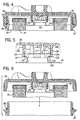
- Cover 30 has a plurality of axially extending cantilever legs 102, 104, etc., Figs. 3-9, gripping end cap 40 in detent relation, with the cantilever legs 102, 104 being deflectable radially outwardly to release end cap 40.
- the cantilever legs 102, 104 have fixed root ends such as 106, 108, Fig. 5, at cover 30, and extend axially into the housing to inner free ends 110, 112 having radially inwardly pointing feet 114, 116.
- End cap 40 has a mushroom-shaped boss 118, Figs.
- Cantilever legs 102, 104, etc. extend axially into housing 22 to an inner axial reach at free ends 110, 112 beyond the noted first end 36 of filter element 34, and grip end cap 40 at mushroom-shaped boss 118.
- Annular filter element 34 has the noted hollow interior 54 which is spanned and closed by end cap 40 at first end 36.
- End cap 40 has a central concave section 128, Figs. 6, 10, extending into hollow interior 54.
- Cantilever legs 102, 104, etc. extend into concave section 128 and engage the end cap at mushroom-shaped boss 118 in detent relation as above described.
- Annular filter element 34 at end cap 40 may be mounted to cover 30 before or after insertion into housing 22.
- annular filter element 34 at end cap 40 is axially pulled from the housing by cantilever legs 102, 104 at feet 114, 116.
- the end cap and the annular filter element may be inverted, Fig. 11, such that the cover 30 provides a drip pan for the diesel fuel oil.
Landscapes
- Chemical & Material Sciences (AREA)
- Chemical Kinetics & Catalysis (AREA)
- Lubrication Details And Ventilation Of Internal Combustion Engines (AREA)
- Filtration Of Liquid (AREA)
Description
- Fig. 1
- shows a filter known in the prior art, except for the internal filter element cover grip combination,
- Fig. 2
- is a sectional view taken along line 2-2 of Fig. 1 and illustrating the filter element cover grip combination in accordance with the present invention,
- Fig. 3
- is an exploded perspective view of a portion of Fig. 2,
- Fig. 4
- is an enlarged view of a portion of Fig. 2,
- Fig. 5
- is a further enlarged view of a portion of Fig. 2,
- Fig. 6
- is an exploded perspective view illustrating assembly,
- Fig. 7
- is an inside end view of the cover of Fig. 6,
- Fig. 8
- is a view like a portion of Fig. 5 and illustrating assembly,
- Fig. 9
- is a view like Fig. 4 and illustrating assembly,
- Fig. 10
- is a view like Fig. 9 and further illustrating assembly,
- Fig. 11
- is a view like Fig. 4 inverted.
Claims (6)
- A filter comprisingwherein said annular filter element (34) has a hollow interior, and said end cap (40) spans and closes said hollow interior,a housing (22) extending axially along an axis (24) between distally opposite first and second ends (26, 28),a cover (30) removably mounted to said housing (22) and closing said first end (26),an annular filter element (34) extending axially in said housing (22) between distally opposite first and second ends (36, 38) respectively at said first and second ends (26, 28) of said housing (22),an end cap (40) at said first end (36) of said annular filter element (34),
wherein said cover (30) has a plurality of axially extending cantilever legs (102, 104)
wherein said end cap (40) has a central mushroom-shaped boss (118), wherein said central mushroom-shaped boss (118) of said end cap (40) is releasably engaged and gripped by said cantilever legs (102, 104) of said cover (30) including upon removal of said cover (30) from said housing (22),
characterized in that
said end cap (40) has a central concave section (128) extending into said hollow interior (54),
said central mushroom-shaped boss (118) is extending from said concave section (128) axially towards said cover (30) and
said cantilever legs (102, 104) extend into said concave section (128) and engage said end cap (40) at said central mushroom-shaped boss (118) in detent relation. - Filter according to claim 1, characterized in that said cantilever legs (102, 104) are deflectable radially outwardly to release said end cap (40)
- Filter according to claim 2, characterized in that said cantilever legs (102, 104) have a fixed root end (108, 106) at said cover (30) and extend axially into said housing (22) to inner free ends (110, 112) having radially inwardly pointing feet (114, 116), and that said central mushroom-shaped boss (118) has a head (120) of a first outer diameter facing said cover (30), and a trunk (122) of a second outer diameter extending axially from said head (120) on the opposite side thereof from said cover (30), said first outer diameter being greater than said second outer diameter, said cover (30) and said central mushroom-shaped boss (118) being axially engageable, with said feet (114, 116) sliding axially along said head (120) and with said cantilever legs (102, 104) deflecting radially outwardly and then said feet (114 116) sliding axially past said head (120) and said cantilever legs (102, 104) deflecting back radially inwardly with said feet (114, 116) behind said head (120) on the axially opposite side thereof from said cover (30).
- Filter according to claim 3, characterized in that said cover (30) is threadingly mounted to said housing (22) and is rotatable about said axis (24), and that said cantilever legs (102, 104) loosely radially grip said boss (118) and slide circumferentially along said head (120) during rotation of said cover (30).
- Filter according to any one of the preceding claims, characterized in that said cantilever legs (102, 104) are extending axially into said housing (22) to an inner axial reach beyond said first end (36) of said annular filter element (34) and are gripping said end cap (40).
- Filter according to any one of the preceding claims, characterized in that said end cap (40) is permanently mounted to said first end (36) to said annular filter element (34).
Applications Claiming Priority (2)
| Application Number | Priority Date | Filing Date | Title |
|---|---|---|---|
| US09/934,508 US6627078B1 (en) | 2001-08-22 | 2001-08-22 | Filter element cover grip |
| US934508 | 2001-08-22 |
Publications (2)
| Publication Number | Publication Date |
|---|---|
| EP1285683A1 EP1285683A1 (en) | 2003-02-26 |
| EP1285683B1 true EP1285683B1 (en) | 2004-11-03 |
Family
ID=25465664
Family Applications (1)
| Application Number | Title | Priority Date | Filing Date |
|---|---|---|---|
| EP02015148A Expired - Lifetime EP1285683B1 (en) | 2001-08-22 | 2002-07-06 | Replaceable filter element and snap-on filter lid assembly |
Country Status (3)
| Country | Link |
|---|---|
| US (1) | US6627078B1 (en) |
| EP (1) | EP1285683B1 (en) |
| DE (1) | DE60201791T2 (en) |
Families Citing this family (17)
| Publication number | Priority date | Publication date | Assignee | Title |
|---|---|---|---|---|
| US6770196B2 (en) * | 2002-03-20 | 2004-08-03 | Arvin Technologies, Inc. | Filter cap with releasable filter element |
| US6896803B2 (en) * | 2003-03-28 | 2005-05-24 | Arvin Technologies, Inc. | Filter apparatus and associated method |
| US20050056124A1 (en) * | 2003-09-15 | 2005-03-17 | Zulauf Gary B. | Filter cap having a gripping surface |
| DE102004026188A1 (en) * | 2004-05-28 | 2005-12-29 | Brita Gmbh | Filterkcheche and device for the filtration of liquids |
| ATE470493T1 (en) * | 2004-09-29 | 2010-06-15 | 3M Innovative Properties Co | STANDARD WATER FILTER SYSTEM |
| US7708147B2 (en) * | 2004-11-15 | 2010-05-04 | Purolator Filters Na Llc | Fluid filter assembly with notched case |
| US8066791B2 (en) * | 2007-07-20 | 2011-11-29 | Donaldson Company, Inc. | Air cleaner arrangements with internal and external support for cartridge; components; and, methods |
| US7935255B2 (en) * | 2007-09-06 | 2011-05-03 | Cummins Filtration Ip, Inc. | Filter cartridge |
| US8167966B2 (en) * | 2008-04-07 | 2012-05-01 | Cummins Filtration Ip, Inc. | Replaceable filter cartridge with removal feature |
| US8501001B2 (en) | 2008-11-05 | 2013-08-06 | Cummins Filtration Ip, Inc. | Fluid filter with an attachment structure on an endplate of the filtering element |
| DE102015207231B4 (en) * | 2015-04-21 | 2017-09-14 | Mahle International Gmbh | filtering device |
| WO2017035123A1 (en) * | 2015-08-25 | 2017-03-02 | Cummins Filtration Ip, Inc | Filter precleaner |
| WO2018044312A1 (en) * | 2016-09-01 | 2018-03-08 | Cummins Filtration Ip, Inc. | Handle geometry for plastic end plates |
| DE102017011081B4 (en) * | 2016-12-09 | 2019-10-17 | Mann+Hummel Gmbh | Filter system, use of the filter system and filter element |
| DE102017003551A1 (en) * | 2017-04-12 | 2018-10-18 | Daimler Ag | Filter element for an air filter of a motor vehicle |
| WO2021251875A1 (en) | 2020-06-11 | 2021-12-16 | Husqvarna Ab | Lid arrangement for a dust extractor comprising a dust cyclone container and a fine filter section |
| USD1072163S1 (en) * | 2022-04-27 | 2025-04-22 | Wuhu TianHao E-commerce CO., LTD. | Fuel water separator |
Family Cites Families (6)
| Publication number | Priority date | Publication date | Assignee | Title |
|---|---|---|---|---|
| DE8714656U1 (en) | 1987-11-04 | 1987-12-17 | Ing. Walter Hengst GmbH & Co KG, 4400 Münster | Oil filter for cleaning lubricating oil |
| DE4344588A1 (en) | 1993-12-24 | 1995-06-29 | Knecht Filterwerke Gmbh | Air bleed channel for fuel filter |
| DE19502020C2 (en) | 1995-01-24 | 2002-02-28 | Mann & Hummel Filter | liquid filters |
| DE19642641C2 (en) | 1995-11-27 | 1998-03-19 | Knecht Filterwerke Gmbh | Plastic screw cap in bell shape for a filter housing |
| EP1008375A1 (en) | 1998-12-11 | 2000-06-14 | Baldwin Filters, Inc. | Disposable fuel filter element and lid assembly |
| US6235194B1 (en) * | 2000-03-08 | 2001-05-22 | Parker-Hannifin Corporation | Recharge and filter assembly with replaceable cartridge |
-
2001
- 2001-08-22 US US09/934,508 patent/US6627078B1/en not_active Expired - Lifetime
-
2002
- 2002-07-06 DE DE60201791T patent/DE60201791T2/en not_active Expired - Lifetime
- 2002-07-06 EP EP02015148A patent/EP1285683B1/en not_active Expired - Lifetime
Also Published As
| Publication number | Publication date |
|---|---|
| DE60201791T2 (en) | 2005-03-10 |
| DE60201791D1 (en) | 2004-12-09 |
| US6627078B1 (en) | 2003-09-30 |
| EP1285683A1 (en) | 2003-02-26 |
Similar Documents
| Publication | Publication Date | Title |
|---|---|---|
| US6627078B1 (en) | Filter element cover grip | |
| US5814215A (en) | Oil filter including an integral filter support and housing drain valve assembly | |
| US10179303B2 (en) | Top load liquid filter assembly, system, and methods | |
| EP1479427B1 (en) | Filter apparatus with a quick-drain valve member | |
| EP2767320B1 (en) | Top load liquid filter assembly, system, and methods | |
| US9468870B2 (en) | Fluid filter element | |
| KR100743532B1 (en) | Refill and filter assembly with replaceable cartridge | |
| US4948503A (en) | Oil filter cover in combination with an oil filter cartridge | |
| EA003489B1 (en) | Center tube with built in snap for automotive oil filter | |
| US20180326342A1 (en) | Snap in place natural gas filter | |
| US20080047891A1 (en) | Liquid filter suitable for motor vehicles | |
| US20200368653A1 (en) | Adapter For A Filter Assembly | |
| US11305217B2 (en) | Filter element for liquid filtration | |
| US8741138B2 (en) | Filter with end cap features | |
| JP2014097504A (en) | Filter with ejection mechanism | |
| US5637215A (en) | Fuel filter having improved communication with a contaminant container | |
| AU2008335581A1 (en) | Filter having baseplate with internal gasket location | |
| CN109843409B (en) | bowl of filter assembly | |
| EP0830885A1 (en) | Filer assembly | |
| WO2018102095A1 (en) | Valve-sensor assembly | |
| WO2020185572A1 (en) | Filter element with end cap including coupling features | |
| EP1094203B1 (en) | Oil filter for combustion engine | |
| EP1948345B1 (en) | Fuel filter cartridge apparatus | |
| US20090200221A1 (en) | Liquid filter arrangement and method | |
| JP3775116B2 (en) | Fuel filter device |
Legal Events
| Date | Code | Title | Description |
|---|---|---|---|
| PUAI | Public reference made under article 153(3) epc to a published international application that has entered the european phase |
Free format text: ORIGINAL CODE: 0009012 |
|
| AK | Designated contracting states |
Kind code of ref document: A1 Designated state(s): AT BE BG CH CY CZ DE DK EE ES FI FR GB GR IE IT LI LU MC NL PT SE SK TR |
|
| AX | Request for extension of the european patent |
Extension state: AL LT LV MK RO SI |
|
| 17P | Request for examination filed |
Effective date: 20030312 |
|
| 17Q | First examination report despatched |
Effective date: 20030625 |
|
| AKX | Designation fees paid |
Designated state(s): DE GB |
|
| GRAP | Despatch of communication of intention to grant a patent |
Free format text: ORIGINAL CODE: EPIDOSNIGR1 |
|
| GRAS | Grant fee paid |
Free format text: ORIGINAL CODE: EPIDOSNIGR3 |
|
| GRAA | (expected) grant |
Free format text: ORIGINAL CODE: 0009210 |
|
| AK | Designated contracting states |
Kind code of ref document: B1 Designated state(s): DE GB |
|
| REG | Reference to a national code |
Ref country code: GB Ref legal event code: FG4D |
|
| REF | Corresponds to: |
Ref document number: 60201791 Country of ref document: DE Date of ref document: 20041209 Kind code of ref document: P |
|
| REG | Reference to a national code |
Ref country code: IE Ref legal event code: FG4D |
|
| PLBE | No opposition filed within time limit |
Free format text: ORIGINAL CODE: 0009261 |
|
| STAA | Information on the status of an ep patent application or granted ep patent |
Free format text: STATUS: NO OPPOSITION FILED WITHIN TIME LIMIT |
|
| 26N | No opposition filed |
Effective date: 20050804 |
|
| REG | Reference to a national code |
Ref country code: DE Ref legal event code: R082 Ref document number: 60201791 Country of ref document: DE Representative=s name: VON ROHR PATENTANWAELTE PARTNERSCHAFT MBB, DE |
|
| PGFP | Annual fee paid to national office [announced via postgrant information from national office to epo] |
Ref country code: GB Payment date: 20130729 Year of fee payment: 12 |
|
| GBPC | Gb: european patent ceased through non-payment of renewal fee |
Effective date: 20140706 |
|
| PG25 | Lapsed in a contracting state [announced via postgrant information from national office to epo] |
Ref country code: GB Free format text: LAPSE BECAUSE OF NON-PAYMENT OF DUE FEES Effective date: 20140706 |
|
| PGFP | Annual fee paid to national office [announced via postgrant information from national office to epo] |
Ref country code: DE Payment date: 20180727 Year of fee payment: 17 |
|
| REG | Reference to a national code |
Ref country code: DE Ref legal event code: R119 Ref document number: 60201791 Country of ref document: DE |
|
| PG25 | Lapsed in a contracting state [announced via postgrant information from national office to epo] |
Ref country code: DE Free format text: LAPSE BECAUSE OF NON-PAYMENT OF DUE FEES Effective date: 20200201 |