EP1284929B1 - Autocycle control of cooling water systems - Google Patents
Autocycle control of cooling water systems Download PDFInfo
- Publication number
- EP1284929B1 EP1284929B1 EP01920910.5A EP01920910A EP1284929B1 EP 1284929 B1 EP1284929 B1 EP 1284929B1 EP 01920910 A EP01920910 A EP 01920910A EP 1284929 B1 EP1284929 B1 EP 1284929B1
- Authority
- EP
- European Patent Office
- Prior art keywords
- mole
- cooling water
- control
- tagged
- tagged treatment
- Prior art date
- Legal status (The legal status is an assumption and is not a legal conclusion. Google has not performed a legal analysis and makes no representation as to the accuracy of the status listed.)
- Expired - Lifetime
Links
- 239000000498 cooling water Substances 0.000 title claims description 58
- XLYOFNOQVPJJNP-UHFFFAOYSA-N water Substances O XLYOFNOQVPJJNP-UHFFFAOYSA-N 0.000 claims description 63
- 229920000642 polymer Polymers 0.000 claims description 61
- 238000000034 method Methods 0.000 claims description 23
- 238000001816 cooling Methods 0.000 claims description 21
- 239000000700 radioactive tracer Substances 0.000 claims description 21
- KKSNTCYLMGYFFB-UHFFFAOYSA-N (prop-2-enoylamino)methanesulfonic acid Chemical compound OS(=O)(=O)CNC(=O)C=C KKSNTCYLMGYFFB-UHFFFAOYSA-N 0.000 claims description 8
- SMZOUWXMTYCWNB-UHFFFAOYSA-N 2-(2-methoxy-5-methylphenyl)ethanamine Chemical compound COC1=CC=C(C)C=C1CCN SMZOUWXMTYCWNB-UHFFFAOYSA-N 0.000 claims description 8
- NIXOWILDQLNWCW-UHFFFAOYSA-N 2-Propenoic acid Natural products OC(=O)C=C NIXOWILDQLNWCW-UHFFFAOYSA-N 0.000 claims description 8
- HRPVXLWXLXDGHG-UHFFFAOYSA-N Acrylamide Chemical compound NC(=O)C=C HRPVXLWXLXDGHG-UHFFFAOYSA-N 0.000 claims description 8
- 239000000203 mixture Substances 0.000 claims description 6
- 150000003839 salts Chemical group 0.000 claims description 4
- XJHABGPPCLHLLV-UHFFFAOYSA-N benzo[de]isoquinoline-1,3-dione Chemical compound C1=CC(C(=O)NC2=O)=C3C2=CC=CC3=C1 XJHABGPPCLHLLV-UHFFFAOYSA-N 0.000 claims description 3
- SLBOQBILGNEPEB-UHFFFAOYSA-N 1-chloroprop-2-enylbenzene Chemical compound C=CC(Cl)C1=CC=CC=C1 SLBOQBILGNEPEB-UHFFFAOYSA-N 0.000 claims description 2
- KITJEUNOEAXPIT-UHFFFAOYSA-N 8-[(3-ethenylphenyl)methoxy]pyrene-1,3,6-trisulfonic acid Chemical compound C12=C3C=4C=CC2=C(S(O)(=O)=O)C=C(S(O)(=O)=O)C1=CC=C3C(S(=O)(=O)O)=CC=4OCC1=CC=CC(C=C)=C1 KITJEUNOEAXPIT-UHFFFAOYSA-N 0.000 claims description 2
- BFIMDLLWMMDVTQ-UHFFFAOYSA-N 8-[(4-ethenylphenyl)methoxy]pyrene-1,3,6-trisulfonic acid Chemical compound C12=C3C=4C=CC2=C(S(O)(=O)=O)C=C(S(O)(=O)=O)C1=CC=C3C(S(=O)(=O)O)=CC=4OCC1=CC=C(C=C)C=C1 BFIMDLLWMMDVTQ-UHFFFAOYSA-N 0.000 claims description 2
- 239000000047 product Substances 0.000 description 45
- 241000894007 species Species 0.000 description 15
- VTYYLEPIZMXCLO-UHFFFAOYSA-L Calcium carbonate Chemical compound [Ca+2].[O-]C([O-])=O VTYYLEPIZMXCLO-UHFFFAOYSA-L 0.000 description 14
- 239000000126 substance Substances 0.000 description 10
- BHPQYMZQTOCNFJ-UHFFFAOYSA-N Calcium cation Chemical compound [Ca+2] BHPQYMZQTOCNFJ-UHFFFAOYSA-N 0.000 description 8
- 229910000019 calcium carbonate Inorganic materials 0.000 description 7
- 230000007423 decrease Effects 0.000 description 5
- 150000002500 ions Chemical class 0.000 description 5
- QAOWNCQODCNURD-UHFFFAOYSA-L Sulfate Chemical compound [O-]S([O-])(=O)=O QAOWNCQODCNURD-UHFFFAOYSA-L 0.000 description 4
- OSGAYBCDTDRGGQ-UHFFFAOYSA-L calcium sulfate Chemical compound [Ca+2].[O-]S([O-])(=O)=O OSGAYBCDTDRGGQ-UHFFFAOYSA-L 0.000 description 4
- 238000005260 corrosion Methods 0.000 description 4
- 230000007797 corrosion Effects 0.000 description 4
- 230000004044 response Effects 0.000 description 4
- 239000011575 calcium Substances 0.000 description 3
- 238000010586 diagram Methods 0.000 description 3
- 229920001109 fluorescent polymer Polymers 0.000 description 3
- 239000008235 industrial water Substances 0.000 description 3
- 239000011777 magnesium Substances 0.000 description 3
- 230000002906 microbiologic effect Effects 0.000 description 3
- 238000012545 processing Methods 0.000 description 3
- 230000008901 benefit Effects 0.000 description 2
- 239000003795 chemical substances by application Substances 0.000 description 2
- 230000000052 comparative effect Effects 0.000 description 2
- 230000003247 decreasing effect Effects 0.000 description 2
- 238000010790 dilution Methods 0.000 description 2
- 239000012895 dilution Substances 0.000 description 2
- 238000005516 engineering process Methods 0.000 description 2
- 239000000178 monomer Substances 0.000 description 2
- 239000002244 precipitate Substances 0.000 description 2
- JOXIMZWYDAKGHI-UHFFFAOYSA-N toluene-4-sulfonic acid Chemical group CC1=CC=C(S(O)(=O)=O)C=C1 JOXIMZWYDAKGHI-UHFFFAOYSA-N 0.000 description 2
- ZRGONDPMOQPTPL-UHFFFAOYSA-N 1-[2-(2-hydroxyethylsulfanyl)ethyl]-2-methyl-5-phenylpyrrole-3-carboxylic acid Chemical compound OCCSCCN1C(C)=C(C(O)=O)C=C1C1=CC=CC=C1 ZRGONDPMOQPTPL-UHFFFAOYSA-N 0.000 description 1
- OYPRJOBELJOOCE-UHFFFAOYSA-N Calcium Chemical compound [Ca] OYPRJOBELJOOCE-UHFFFAOYSA-N 0.000 description 1
- FYYHWMGAXLPEAU-UHFFFAOYSA-N Magnesium Chemical compound [Mg] FYYHWMGAXLPEAU-UHFFFAOYSA-N 0.000 description 1
- 239000002253 acid Substances 0.000 description 1
- 230000009471 action Effects 0.000 description 1
- 230000002411 adverse Effects 0.000 description 1
- 150000001412 amines Chemical class 0.000 description 1
- 230000003115 biocidal effect Effects 0.000 description 1
- 239000003139 biocide Substances 0.000 description 1
- 229910052791 calcium Inorganic materials 0.000 description 1
- 229910001424 calcium ion Inorganic materials 0.000 description 1
- 230000008859 change Effects 0.000 description 1
- 238000004891 communication Methods 0.000 description 1
- 230000001627 detrimental effect Effects 0.000 description 1
- 230000000694 effects Effects 0.000 description 1
- 239000007850 fluorescent dye Substances 0.000 description 1
- 239000004615 ingredient Substances 0.000 description 1
- 239000003112 inhibitor Substances 0.000 description 1
- 238000012417 linear regression Methods 0.000 description 1
- 229910052749 magnesium Inorganic materials 0.000 description 1
- 239000000463 material Substances 0.000 description 1
- 238000005259 measurement Methods 0.000 description 1
- 230000007246 mechanism Effects 0.000 description 1
- 230000001376 precipitating effect Effects 0.000 description 1
- 238000001556 precipitation Methods 0.000 description 1
- 230000008569 process Effects 0.000 description 1
- 238000005086 pumping Methods 0.000 description 1
- 238000000611 regression analysis Methods 0.000 description 1
- 238000005070 sampling Methods 0.000 description 1
- 239000000243 solution Substances 0.000 description 1
- 238000012360 testing method Methods 0.000 description 1
- 229920003169 water-soluble polymer Polymers 0.000 description 1
Images

Classifications
-
- G—PHYSICS
- G01—MEASURING; TESTING
- G01N—INVESTIGATING OR ANALYSING MATERIALS BY DETERMINING THEIR CHEMICAL OR PHYSICAL PROPERTIES
- G01N17/00—Investigating resistance of materials to the weather, to corrosion, or to light
- G01N17/008—Monitoring fouling
-
- C—CHEMISTRY; METALLURGY
- C02—TREATMENT OF WATER, WASTE WATER, SEWAGE, OR SLUDGE
- C02F—TREATMENT OF WATER, WASTE WATER, SEWAGE, OR SLUDGE
- C02F1/00—Treatment of water, waste water, or sewage
- C02F1/008—Control or steering systems not provided for elsewhere in subclass C02F
-
- G—PHYSICS
- G01—MEASURING; TESTING
- G01N—INVESTIGATING OR ANALYSING MATERIALS BY DETERMINING THEIR CHEMICAL OR PHYSICAL PROPERTIES
- G01N33/00—Investigating or analysing materials by specific methods not covered by groups G01N1/00 - G01N31/00
- G01N33/18—Water
-
- C—CHEMISTRY; METALLURGY
- C02—TREATMENT OF WATER, WASTE WATER, SEWAGE, OR SLUDGE
- C02F—TREATMENT OF WATER, WASTE WATER, SEWAGE, OR SLUDGE
- C02F2103/00—Nature of the water, waste water, sewage or sludge to be treated
- C02F2103/02—Non-contaminated water, e.g. for industrial water supply
- C02F2103/023—Water in cooling circuits
-
- C—CHEMISTRY; METALLURGY
- C02—TREATMENT OF WATER, WASTE WATER, SEWAGE, OR SLUDGE
- C02F—TREATMENT OF WATER, WASTE WATER, SEWAGE, OR SLUDGE
- C02F2209/00—Controlling or monitoring parameters in water treatment
- C02F2209/40—Liquid flow rate
-
- C—CHEMISTRY; METALLURGY
- C02—TREATMENT OF WATER, WASTE WATER, SEWAGE, OR SLUDGE
- C02F—TREATMENT OF WATER, WASTE WATER, SEWAGE, OR SLUDGE
- C02F2303/00—Specific treatment goals
- C02F2303/08—Corrosion inhibition
-
- C—CHEMISTRY; METALLURGY
- C02—TREATMENT OF WATER, WASTE WATER, SEWAGE, OR SLUDGE
- C02F—TREATMENT OF WATER, WASTE WATER, SEWAGE, OR SLUDGE
- C02F2303/00—Specific treatment goals
- C02F2303/20—Prevention of biofouling
-
- C—CHEMISTRY; METALLURGY
- C02—TREATMENT OF WATER, WASTE WATER, SEWAGE, OR SLUDGE
- C02F—TREATMENT OF WATER, WASTE WATER, SEWAGE, OR SLUDGE
- C02F5/00—Softening water; Preventing scale; Adding scale preventatives or scale removers to water, e.g. adding sequestering agents
- C02F5/08—Treatment of water with complexing chemicals or other solubilising agents for softening, scale prevention or scale removal, e.g. adding sequestering agents
-
- G—PHYSICS
- G01—MEASURING; TESTING
- G01N—INVESTIGATING OR ANALYSING MATERIALS BY DETERMINING THEIR CHEMICAL OR PHYSICAL PROPERTIES
- G01N33/00—Investigating or analysing materials by specific methods not covered by groups G01N1/00 - G01N31/00
- G01N33/18—Water
- G01N33/1853—Hardness of water
-
- G—PHYSICS
- G01—MEASURING; TESTING
- G01N—INVESTIGATING OR ANALYSING MATERIALS BY DETERMINING THEIR CHEMICAL OR PHYSICAL PROPERTIES
- G01N33/00—Investigating or analysing materials by specific methods not covered by groups G01N1/00 - G01N31/00
- G01N33/18—Water
- G01N33/186—Water using one or more living organisms, e.g. a fish
- G01N33/1866—Water using one or more living organisms, e.g. a fish using microorganisms
-
- Y—GENERAL TAGGING OF NEW TECHNOLOGICAL DEVELOPMENTS; GENERAL TAGGING OF CROSS-SECTIONAL TECHNOLOGIES SPANNING OVER SEVERAL SECTIONS OF THE IPC; TECHNICAL SUBJECTS COVERED BY FORMER USPC CROSS-REFERENCE ART COLLECTIONS [XRACs] AND DIGESTS
- Y10—TECHNICAL SUBJECTS COVERED BY FORMER USPC
- Y10T—TECHNICAL SUBJECTS COVERED BY FORMER US CLASSIFICATION
- Y10T137/00—Fluid handling
- Y10T137/0318—Processes
- Y10T137/0324—With control of flow by a condition or characteristic of a fluid
- Y10T137/0329—Mixing of plural fluids of diverse characteristics or conditions
Definitions
- the present invention relates to a method for controlling cooling water systems by measuring the consumption of fluorescent polymers.
- a cooling water system comprises a cooling tower; heat exchangers, pumps and all necessary piping to move water through the system. Control of a cooling water system is based on balancing the desire to run the cooling water system at the highest concentration cycles possible without incurring detrimental scaling, corrosion, fouling or microbiological control situations.
- a concentration cycle is defined for a specific species as: Specific Species Level i ⁇ n Cooling Water Tower Specific Species Level i ⁇ n Make - u ⁇ p Water
- the specific species is the calcium ion hereinafter "Ca +2 ": if a cooling water system is running at 500 ppm Ca +2 with 150 ppm Ca +2 in the makeup water, the cooling water system is running at 3.3 concentration cycles.
- the maximum concentration cycles for a cooling water system are limited by the undesirable events, such as scaling and corrosion, which occur when the amount of specific species in the cooling water tower reaches a certain level, such that the species contributes to these problems.
- Controlling the concentration cycles is typically done by controlling the flow rate of "fresh" water (from one or more sources) known as make-up water into the system and by controlling the main flow rate out of the system, referred to as blowdown.
- a pump or valve controls the flow of make-up water into the cooling tower and a level controller is typically used in the cooling tower reservoir or "sump".
- the level controller is linked to the make-up water pump or valve and when the water in the sump decreases to a point lower than the setpoint for the level controller the make-up water pump or valve is activated.
- Conductivity is the typical method of blowdown control.
- conductivity is defined as the measurement of electrical conductivity of water with electrical conductivity being present in the water due to ionic species being present in the water.
- Conductivity can be used to control bleed of blowdown because conductivity can readily be used to estimate the overall amount of ionic species present in the water and a simple controller can be set to open a valve or pump and start blowdown when the conductivity of the reservoir water reaches above a certain setpoint.
- conductivity cannot provide information about scaling tendency or actual scaling and use of conductivity can cause "catastrophic failure", where scaling causes the cooling water system to overcycle and scale further.
- a timer can control bleed of blowdown without actually measuring any of the specific species in the water.
- water flow meters on the make-up and blowdown can be used, in conjunction with a microprocessor controller to do an overall cooling water mass balance.
- a problem with these known control schemes is that when the blowdown is controlled by conductivity and the make-up is controlled by a level controller, if the composition of the usual make-up water is variable, or if there are alternate sources of make-up water that are significantly different from the usual make-up water source, level controllers and conductivity cannot account for all events that are occurring in the system. In these cases, the cooling water system is typically controlled by the operator being conservative with the conductivity setpoint which thus causes extra undesirable expense due to non-optimal use of treatment chemicals and water.
- a cooling water control system can be set up to feed treatment product based on either a bleed/feed mechanism where the action of blowdown triggers a chemical feed pump or valve that feeds treatment product; or, in the alternative, the cooling water control system feeds treatment product based on timers using a "feeding schedule" or flow meters on the make-up water line trigger the pumping of treatment product based on a certain amount of make-up water being pumped.
- a limitation of these control methods is that none of these systems measure the treatment product concentration directly online, so if there is a mechanical problem, for example, if a pump fails, a drum empties, or high, low or unknown blowdown occurs, system volume changes or makeup water quality changes; the correct treatment product concentration is not maintained. Because this problem is common, typically cooling water systems are either overfed to ensure the level of treatment product in the system does not drop too low as a result of high variability in product dosage or the treatment product is unknowingly underfed. Both overfeeding and underfeeding of treatment product are undesirable due to cost and performance drawbacks.
- TRASAR ® is a registered trademark of Nalco Chemical Company One Nalco Center, Naperville IL 60563 (630) 305-1000).
- the fluorescent signal of the inert fluorescent chemical is then used to determine whether the desired amount of treatment product is present in the cooling tower (and to control blowdown).
- Cooling towers that use both inert tracer(s) and conductivity typically use the following types of information in order to control the tower.
- a cooling tower with typical makeup water having: 150 ppm Ca +2 , 75 ppm Mg +2 , and 100 ppm "M alkalinity"; with a conductivity of 600 ⁇ S/cm (note that conductivity is expressed in units of microsiemans per centimeter), is set to run at 500 ppm Ca +2 .
- the cycles of concentration for this cooling water system are 3.3 (calculated by dividing 500 by 150).
- Running the system at 500 ppm Ca +2 corresponds to a conductivity setpoint of 3.3 times 600 or 1980 ⁇ S/cm.
- the system When the conductivity exceeds this setpoint the system is configured to automatically blowdown a portion of "concentrated” cooling water ("concentrated” referring to system water with an unacceptably high level of ions) which is replaced with “fresh” makeup water (where “fresh” is defined as having a lower level of scaling ions than the “concentrated” cooling water).
- Concentrated referring to system water with an unacceptably high level of ions
- fresh is defined as having a lower level of scaling ions than the “concentrated” cooling water.
- This decreases the conductivity and hardness (Ca +2 and Mg +2 ) ions via dilution. Dilution also reduces the amount of inert tracer chemical in the system. Decreasing the amount of inert tracer in the system decreases the fluorescent signal from the inert tracer.
- the tracer control system is set up to feed a fresh mixture of treatment product and inert tracer chemical to makeup for the decrease in fluorescence that was lost in the blowdown.
- a known method of control of product feed to a cooling water system involves the use of another aspect of tracer technology. This involves using a treatment product containing a polymer that has been "tagged" with a fluorescent moiety. These tagged treatment polymers are not inert, rather, they are supposed to be consumed as they function to treat whatever performance-related condition it is that they are designed to treat. Thus, by measuring the fluorescent signal of the tagged treatment polymer it is possible to determine the amount of consumption of the tagged treatment polymer. By knowing the amount of consumption of the tagged treatment polymer it is possible to use that information to control the feeding of new treatment product containing tagged treatment polymer.
- EP 0504520 discloses a method of determining treating agent concentration added to a water re-circulating system in which the treating agent bears an amine-containing fluorescent moiety tag covalently bonded thereto.
- an autocycle method to control a cooling water system as claimed in claim 1.
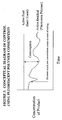
- Figure 1 is a Conceptual Diagram of Control using Fluorescent Polymer Consumption.
- the data in this diagram was obtained by measuring the fluorescent signal of an inert tracer product and the fluorescent signal of a tagged treatment polymer. The difference between the two signals is indicative of the amount of consumption of the tagged treatment polymer. It has been found that the amount of consumption of a tagged treatment polymer can be used to control the concentration cycles of a cooling water system.
- the tagged treatment polymer used in the instant claimed method is selected from the group consisting of polymers described and claimed in U.S. Patent No.'s 5,128,419 ; 5,171,450 ; 5,216,086 ; 5,260,386 and 5,986,030 , U.S. Patent No 6,344,531 entitled, FLUORESCENT WATER-SOLUBLE POLYMERS, now, U.S. Patent Application 09/465,146 entitled, "FLUORESCENT MONOMERS AND POLYMERS CONTAINING SAME FOR USE IN INDUSTRIAL WATER SYSTEMS" filed 16 December 1999, now pending; and U.S. Patent No 6,645,428 entitled, FLUORESCENT MONOMERS AND TAGGED TREATMENT POLYMERS CONTAINING SAME FOR USE IN INDUSTRIAL WATER SYSTEMS, filed 27 April 2000.
- Preferred tagged treatment polymers are selected from the group consisting of:
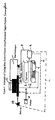
- a PCT is operated to demonstrate the ability to control concentration cycles in a cooling water system based on consumption of a tagged treatment polymer. Control of this tower is afforded by the scheme shown in Figure 2 .
- cooling tower 1 is directly controlled by the consumption of tagged treatment polymer.
- Tagged treatment polymer is part of treatment product 21. It is understood that the treatment product contains tagged treatment polymer as well as other ingredients and that treatment product is not equivalent to tagged treatment polymer.
- Treatment product 21 is pumped to cooling tower 1 through product feed pump 14. Make-up water is added to cooling tower 1 through make-up pump 18. Blowdown from cooling tower 1 is controlled by blowdown pump 24.
- sampling stream 2 flows through two fluorometers.
- First fluorometer 4 measures the fluorescent signal of the inert fluorescent tracer.
- Inert fluorescent tracers suitable for use in the instant claimed method are known to people of ordinary skill in the art.
- One such suitable inert fluorescent tracer is PTSA, which is 1,3,6,8-pyrene tetrasulfonic acid tetrasodium salt.
- Second fluorometer 6 measures the fluorescent signal of the tagged treatment polymer, which is selected from the group of tagged treatment polymers previously described- These fluorescent signals are sent to controller 9 which is in communication with and can control blowdown pump 24 through signal line 8, product feed pump 14 through signal line 10 and make-up pump 18 through signal line 12.
- controller 9 controls both blowdown pump 24 and make-up pump 18; only one of these pumps need be controlled.
- signal line 12 to make-up pump 18 is not used.
- the feed rate of the treatment product 21 using pump 14 is controlled by the fluorescent signal (converted to the concentration) of the inert fluorescent tracer.
- the amount of treatment product comprising tagged treatment polymer being fed must be sufficient to supply the cooling water system with the requisite amount of tagged treatment polymer required for optimum running of the cooling water system.
- the amount of tagged treatment polymer required for optimum running of the cooling water system is known to persons of ordinary skill in the art of cooling water systems.
- the control of feedrate of treatment product can be accomplished by relating the measured consumption of tagged treatment polymer directly to the feedrate of treatment product (using the fluorescent signals of the tagged treatment polymer and inert tracer present in the treatment product to calculate consumption).
- PID Proportional Integral Derivative
- Another method of balancing pump rates is to use computer algorithms and software to configure the pumps such that they act like a PID-controlled pump.
- Two different algorithms have been developed and used to control cooling water systems based on the consumption of a tagged treatment polymer. Both algorithms control a treatment product pump duty cycle over a user defined finite control interval. In both algorithms analog data is obtained at a frequency significantly higher than the control interval. Also in both algorithms, the maximum pump duty cycle will be less than or equal to the control interval such that at each control interval, the pump state should be off.
- the first control algorithm is based on increasing the pump duty cycle by some increment or resetting it to a base value at each control interval as consumption conditions warrant.
- two analog input signals A and B are monitored at a user defined interval.
- A is the amount of treatment product fed to the cooling water system as measured by the inert tracer fluorescent signal
- B is the amount of tagged treatment polymer in the water of the cooling water system as measured by the fluorescent signal of the tagged treatment polymer.
- Relay Zero used to provide power to the product feed pump, is controlled at each interval directly by the response from channel A. If A exceeds a user defined upper setpoint, Relay Zero is toggled off. If A is less than a user defined lower setpoint, Relay Zero is toggled on. Otherwise, Relay Zero status is unchanged.
- An arithmetic operation is applied to channels A and B to determine consumption of the active component.
- Arithmetic operations may be A-B (Consumption), (A-B)/A (% Consumption), or B/A (the ratio of tagged treatment polymer remaining in the system relative to the tagged treatment polymer fed to the system).
- Values of Op are stored over a user-defined number of intervals, and a least squares linear regression analysis is applied to that data as a function of time at each interval. The regression analysis returns the slope, dOp/dt.
- a second relay (Relay One) is controlled based on values of dOp/dt, as described below.
- Relay One primary purpose is to power the blowdown pump or valve solenoid.
- Relay One could also be used to energize an acid feed pump or to energize a make-up water pump or valve solenoid.
- the data is examined at the user defined finite control interval. If A is less than its lower setpoint, no further processing takes place until the next control interval and Relay One remains Off.
- the second control algorithm is based on setting the pump duty cycle for Relay One proportionally based on the Op response.
- Relay Zero is again used to provide power to a product feed pump, while Relay One is used to energize a blowdown pump or valve solenoid.
- Relay Zero is controlled at each interval directly by the response from channel A. If A exceeds a user defined upper setpoint, Relay Zero is toggled off. If A is less than a user defined lower setpoint, Relay Zero is toggled on. Otherwise, Relay Zero status is unchanged.
- the data is also examined at a user defined finite control interval. If A is less than its lower setpoint, no further processing takes place until the next control interval.
- A is greater than its lower setpoint, a proportional response (K) between two user defined operational setpoints is determined for the arithmetic operation (Op) applied to channels A and B. Arithmetic operations are the same as given above (i.e. A-B, (A-B)/A, or B/A). If Op exceeds the upper operational setpoint, K is set to 1. If Op is less than the lower operational setpoint, K is set to 0.
- Relay One is energized for a period of time equivalent to a user defined maximum interval times K.
- the user defined maximum interval should not exceed the decision interval.
- % polymer consumption control as compared to conductivity control, is that control is possible to maintain even if the composition of the make-up water changed.
- the composition of make-up water is quite variable and having the ability to control even when the make-up water changes is a huge advantage over the currently available conductivity control method.
- a PCT configured the same as shown in Figure 2 was controlled at a treatment product feed rate of 250 ppm and 15% tagged polymer consumption.
- the controller was set to control the treatment product pump (pump 14, Relay Zero) and the blowdown pump (pump 24, Relay One).
- the water used in the PCT did not have measurable background fluorescence.
- Figure 3 shows the % polymer consumption and conductivity during a make-up water upset.
- the first make-up water source contained 150 ppm Ca (as CaCO 3 ), 75 ppm Mg (as CaCO 3 ), 110 ppm total alkalinity (as CaCO 3 ), and 72 ppm sulfate (as SO 4 ), with a conductivity of approximately 670 ⁇ S/cm.
- the second make-up water source contained 300 ppm Ca (as CaCO 3 ), 150 ppm Mg (as CaCO 3 ), 110 ppm total alkalinity (as CaCO 3 ), and 249 ppm sulfate (as SO 4 ), with a conductivity of approximately 1190 ⁇ S/cm.
- the second make-up water source contained higher levels of hardness and sulfate, as indicated by the higher conductivity.
- the tendency of the second make-up water to form scale was actually less than the first make-up water source, because of the increased levels of sulfate.
- the controller maintained the polymer consumption level, and allowed the tower to cycle to higher cycles of concentration as indicated by the increase in conductivity.
- the concentration cycles splits were the same for both make-up water sources; this indicates that control of the cooling water system, with respect to scale was also maintained.
Landscapes
- Life Sciences & Earth Sciences (AREA)
- Chemical & Material Sciences (AREA)
- Health & Medical Sciences (AREA)
- Pathology (AREA)
- Engineering & Computer Science (AREA)
- Environmental & Geological Engineering (AREA)
- Physics & Mathematics (AREA)
- Analytical Chemistry (AREA)
- Biochemistry (AREA)
- General Health & Medical Sciences (AREA)
- General Physics & Mathematics (AREA)
- Immunology (AREA)
- Ecology (AREA)
- Biodiversity & Conservation Biology (AREA)
- Food Science & Technology (AREA)
- Medicinal Chemistry (AREA)
- Environmental Sciences (AREA)
- Hydrology & Water Resources (AREA)
- Water Supply & Treatment (AREA)
- Organic Chemistry (AREA)
- Preventing Corrosion Or Incrustation Of Metals (AREA)
- Treatment Of Water By Ion Exchange (AREA)
- Investigating, Analyzing Materials By Fluorescence Or Luminescence (AREA)
- Separation Using Semi-Permeable Membranes (AREA)
Description
- The present invention relates to a method for controlling cooling water systems by measuring the consumption of fluorescent polymers.
- A cooling water system comprises a cooling tower; heat exchangers, pumps and all necessary piping to move water through the system. Control of a cooling water system is based on balancing the desire to run the cooling water system at the highest concentration cycles possible without incurring detrimental scaling, corrosion, fouling or microbiological control situations.
- A concentration cycle is defined for a specific species as:

- For example, when the specific species is the calcium ion hereinafter "Ca+2": if a cooling water system is running at 500 ppm Ca+2 with 150 ppm Ca+2 in the makeup water, the cooling water system is running at 3.3 concentration cycles. In operating a cooling water system it is desirable to achieve the maximum number of concentration cycles to avoid unnecessary loss of water in,blowdown as well as unnecessary overfeeding of treatment chemicals including but not limited to, treatment polymers. The maximum concentration cycles for a cooling water system are limited by the undesirable events, such as scaling and corrosion, which occur when the amount of specific species in the cooling water tower reaches a certain level, such that the species contributes to these problems.
- There are several currently known ways used to control the concentration cycles in cooling water systems. Controlling the concentration cycles is typically done by controlling the flow rate of "fresh" water (from one or more sources) known as make-up water into the system and by controlling the main flow rate out of the system, referred to as blowdown. In order to control makeup water flow, a pump or valve controls the flow of make-up water into the cooling tower and a level controller is typically used in the cooling tower reservoir or "sump". The level controller is linked to the make-up water pump or valve and when the water in the sump decreases to a point lower than the setpoint for the level controller the make-up water pump or valve is activated.
- Conductivity is the typical method of blowdown control. For purposes of this patent application, conductivity is defined as the measurement of electrical conductivity of water with electrical conductivity being present in the water due to ionic species being present in the water. Conductivity can be used to control bleed of blowdown because conductivity can readily be used to estimate the overall amount of ionic species present in the water and a simple controller can be set to open a valve or pump and start blowdown when the conductivity of the reservoir water reaches above a certain setpoint. There are limits to how useful conductivity is for control of a cooling water system as conductivity is nothing more than an indirect measure of the amount of ionic species present. Therefore, conductivity cannot provide information about scaling tendency or actual scaling and use of conductivity can cause "catastrophic failure", where scaling causes the cooling water system to overcycle and scale further.
- Alternatively, a timer can control bleed of blowdown without actually measuring any of the specific species in the water. In addition to or in place of the above control schemes, water flow meters on the make-up and blowdown can be used, in conjunction with a microprocessor controller to do an overall cooling water mass balance.
- A problem with these known control schemes, is that when the blowdown is controlled by conductivity and the make-up is controlled by a level controller, if the composition of the usual make-up water is variable, or if there are alternate sources of make-up water that are significantly different from the usual make-up water source, level controllers and conductivity cannot account for all events that are occurring in the system. In these cases, the cooling water system is typically controlled by the operator being conservative with the conductivity setpoint which thus causes extra undesirable expense due to non-optimal use of treatment chemicals and water.
- Many cooling water systems use treatment products to control undesirable events such as scaling, corrosion, fouling and microbiological growth. These treatment products comprise polymers and other materials and are known to people of ordinary skill in the art of cooling water systems. A cooling water control system can be set up to feed treatment product based on either a bleed/feed mechanism where the action of blowdown triggers a chemical feed pump or valve that feeds treatment product; or, in the alternative, the cooling water control system feeds treatment product based on timers using a "feeding schedule" or flow meters on the make-up water line trigger the pumping of treatment product based on a certain amount of make-up water being pumped. A limitation of these control methods is that none of these systems measure the treatment product concentration directly online, so if there is a mechanical problem, for example, if a pump fails, a drum empties, or high, low or unknown blowdown occurs, system volume changes or makeup water quality changes; the correct treatment product concentration is not maintained. Because this problem is common, typically cooling water systems are either overfed to ensure the level of treatment product in the system does not drop too low as a result of high variability in product dosage or the treatment product is unknowingly underfed. Both overfeeding and underfeeding of treatment product are undesirable due to cost and performance drawbacks.
- One aspect of known control schemes is an inert fluorescent chemical being added to the cooling water system in a known proportion to the active component of the treatment product feed and the use of a fluorometer to monitor the fluorescent signal of the inert fluorescent chemical. This is commercially available as TRASAR®. TRASAR® is a registered trademark of Nalco Chemical Company One Nalco Center, Naperville IL 60563 (630) 305-1000). The fluorescent signal of the inert fluorescent chemical is then used to determine whether the desired amount of treatment product is present in the cooling tower (and to control blowdown).
- Many current cooling towers use inert fluorescent tracers to control the treatment product level in the system and also use a conductivity controller to measure the conductivity in the water.
- Cooling towers that use both inert tracer(s) and conductivity typically use the following types of information in order to control the tower. For example, a cooling tower with typical makeup water having: 150 ppm Ca+2, 75 ppm Mg+2, and 100 ppm "M alkalinity"; with a conductivity of 600 µS/cm (note that conductivity is expressed in units of microsiemans per centimeter), is set to run at 500 ppm Ca+2. In order to operate within acceptable levels, the cycles of concentration for this cooling water system are 3.3 (calculated by dividing 500 by 150). Running the system at 500 ppm Ca+2 corresponds to a conductivity setpoint of 3.3 times 600 or 1980 µS/cm. When the conductivity exceeds this setpoint the system is configured to automatically blowdown a portion of "concentrated" cooling water ("concentrated" referring to system water with an unacceptably high level of ions) which is replaced with "fresh" makeup water (where "fresh" is defined as having a lower level of scaling ions than the "concentrated" cooling water). This decreases the conductivity and hardness (Ca+2 and Mg+2) ions via dilution. Dilution also reduces the amount of inert tracer chemical in the system. Decreasing the amount of inert tracer in the system decreases the fluorescent signal from the inert tracer. When the fluorescent signal from tracer decreases, the tracer control system is set up to feed a fresh mixture of treatment product and inert tracer chemical to makeup for the decrease in fluorescence that was lost in the blowdown.
- A known method of control of product feed to a cooling water system involves the use of another aspect of tracer technology. This involves using a treatment product containing a polymer that has been "tagged" with a fluorescent moiety. These tagged treatment polymers are not inert, rather, they are supposed to be consumed as they function to treat whatever performance-related condition it is that they are designed to treat. Thus, by measuring the fluorescent signal of the tagged treatment polymer it is possible to determine the amount of consumption of the tagged treatment polymer. By knowing the amount of consumption of the tagged treatment polymer it is possible to use that information to control the feeding of new treatment product containing tagged treatment polymer.
- A recent reference in this area is entitled "High Cycle Cooling Tower Operation: Hurdles and Solutions", Hoots et al, pp. 388-397, was presented at the 60th Annual Meeting of the International Water Conference held on October 18-20,1999.
-
EP 0504520 discloses a method of determining treating agent concentration added to a water re-circulating system in which the treating agent bears an amine-containing fluorescent moiety tag covalently bonded thereto. - New methods and techniques for control of cooling water systems are always desirable.
- According to the invention, there is provided an autocycle method to control a cooling water system, as claimed in
claim 1. -
-
Figure 1 : Conceptual Diagram of Control using Fluorescent Polymer Consumption -
Figure 2 : Schematic of Cooling Water System Control Using Consumption of Fluorescent Tagged Polymer -
Figure 3 : Control of Pilot Cooling Tower Using Consumption Control During Make-Up Water Upset. - For purposes of this patent application, the following terms have the indicated definitions:
- "autocycle" refers to a method for automatically controlling the cycles of concentration in a cooling water system based on consumption of a tagged treatment polymer;
- "concentration cycles" refer to the amount of a species in the tower water relative to the amount of a species in the make-up water;
- "concentration cycle split" is defined as the difference between theoretical cycles of a cooling tower with respect to a specie present in the make-up water which could be consumed by some process (precipitation), usually determined by measuring the concentration of a specie which does not precipitate, and the actual cycles of the specie present in the make-up water which may be consumed. In practice, this can be done by comparing calcium (precipitating ion) cycles with magnesium (less likely to precipitate ion) cycles. The "concentration cycle split" thus gives an indication of the relative measure of scaling in the cooling water system.
- "consumption" in general refers to the difference between the amount of tagged treatment polymer fed and the amount of tagged treatment polymer remaining;
- "inert" refers to the fact that an inert fluorescent tracer is not appreciably or significantly affected by any other chemistry in the cooling water system, or by the other system parameters such as metallurgical composition, microbiological activity, biocide concentration, heat changes or overall heat content. To quantify what is meant by "not appreciably or significantly affected", this statement means that an inert fluorescent compound has no more than a 10% change in its fluorescent signal, under conditions normally encountered in cooling water systems. Conditions normally encountered in cooling water systems are known to people of ordinary skill in the art of industrial water systems.
- "PCT" refers to a Pilot Cooling Tower;
- "treatment active" is defined as any component of a treatment chemical that performs a desired function upon addition to a cooling water system.
- "tagged treatment polymer" is a polymer that has been "tagged" with a fluorescent moiety wherein said polymer is capable of functioning as a scale or corrosion inhibitor in a cooling water system.
-
Figure 1 is a Conceptual Diagram of Control using Fluorescent Polymer Consumption. The data in this diagram was obtained by measuring the fluorescent signal of an inert tracer product and the fluorescent signal of a tagged treatment polymer. The difference between the two signals is indicative of the amount of consumption of the tagged treatment polymer. It has been found that the amount of consumption of a tagged treatment polymer can be used to control the concentration cycles of a cooling water system. - The tagged treatment polymer used in the instant claimed method is selected from the group consisting of polymers described and claimed in
U.S. Patent No.'s 5,128,419 ;5,171,450 ;5,216,086 ;5,260,386 and5,986,030 ,U.S. Patent No 6,344,531 entitled, FLUORESCENT WATER-SOLUBLE POLYMERS, now,U.S. Patent Application 09/465,146 U.S. Patent No 6,645,428 entitled, FLUORESCENT MONOMERS AND TAGGED TREATMENT POLYMERS CONTAINING SAME FOR USE IN INDUSTRIAL WATER SYSTEMS, filed 27 April 2000. - Preferred tagged treatment polymers are selected from the group consisting of:
- 59.95 mole % acrylic acid/19.95 mole % acrylamide/ 20 mole % N-(sulfomethyl)acrylamide/ 0.1 mole % 8-(4-vinylbenzyloxy)-1,3,6-pyrenetrisulfonic acid, trisodium salt;
- 59.95 mole % acrylic acid/19.95 mole % acrylamide/ 20 mole % N-(sulfomethyl)acrylamide/ 0.1 mole % 8-(3-vinylbenzyloxy)-1,3,6-pyrenetrisulfonic acid, trisodium salt;
- 59.9 mole % acrylic acid/19.9 mole % acrylamide/ 20 mole % N-(sulfomethyl)acrylamide/ 0.2 mole % 4-methoxy-N-(3-N',N'-dimethylaminopropyl) naphthalimide vinylbenzyl chloride quaternary salt; and
- 59.96 mole % acrylic acid/19.96 mole % acrylamide/ 20 mole % N-(sulfomethyl)acrylamide/ 0.08 mole % 4-methoxy-N-(3-N',N'-dimethylaminopropyl) naphthalimide 2-hydroxy-3-allyloxy propyl quaternary salt.
- A PCT is operated to demonstrate the ability to control concentration cycles in a cooling water system based on consumption of a tagged treatment polymer. Control of this tower is afforded by the scheme shown in
Figure 2 . InFigure 2 ,cooling tower 1 is directly controlled by the consumption of tagged treatment polymer. Tagged treatment polymer is part of treatment product 21. It is understood that the treatment product contains tagged treatment polymer as well as other ingredients and that treatment product is not equivalent to tagged treatment polymer. Treatment product 21 is pumped tocooling tower 1 through product feed pump 14. Make-up water is added tocooling tower 1 through make-uppump 18. Blowdown fromcooling tower 1 is controlled byblowdown pump 24. - In this control scheme, sampling stream 2 flows through two fluorometers. First fluorometer 4 measures the fluorescent signal of the inert fluorescent tracer. Inert fluorescent tracers suitable for use in the instant claimed method are known to people of ordinary skill in the art. One such suitable inert fluorescent tracer is PTSA, which is 1,3,6,8-pyrene tetrasulfonic acid tetrasodium salt. Second fluorometer 6 measures the fluorescent signal of the tagged treatment polymer, which is selected from the group of tagged treatment polymers previously described- These fluorescent signals are sent to controller 9 which is in communication with and can control
blowdown pump 24 through signal line 8,product feed pump 14 throughsignal line 10 and make-uppump 18 through signal line 12. In conducting the method of the instant claimed invention it is not required that controller 9 controls bothblowdown pump 24 and make-uppump 18; only one of these pumps need be controlled. For purposes of the description of cooling tower inFigure 2 , signal line 12 to make-uppump 18 is not used. - A suitable fluorometer and controller for use in conducting the method of the instant claimed invention is described and claimed in
U.S. Patent No 6,369,894 , entitled, "MODULAR FLUOROMETER AND METHOD OF USING SAME TO DETECT ONE OR MORE FLUOROPHORES", issued April 9, 2002. - As per standard technology, the feed rate of the treatment product 21 using
pump 14 is controlled by the fluorescent signal (converted to the concentration) of the inert fluorescent tracer. - In one possible control scheme, blowdown pump is activated when the % consumption of tagged treatment polymer consumption drops below the level set according to the following equation:

where - A is the amount of treatment product fed to the cooling water system as measured by the inert tracer fluorescent signal, and
- B is the amount of tagged treatment polymer in the water of the cooling water system as measured by the fluorescent signal of the tagged treatment polymer.
- In conducting the method of the instant claimed invention it was found that the amount of treatment product comprising tagged treatment polymer being fed must be sufficient to supply the cooling water system with the requisite amount of tagged treatment polymer required for optimum running of the cooling water system. The amount of tagged treatment polymer required for optimum running of the cooling water system is known to persons of ordinary skill in the art of cooling water systems. The control of feedrate of treatment product can be accomplished by relating the measured consumption of tagged treatment polymer directly to the feedrate of treatment product (using the fluorescent signals of the tagged treatment polymer and inert tracer present in the treatment product to calculate consumption).
- In conducting the method of the instant claimed invention it was also found that when control is implemented by linking flowrates, the flowrates must be balanced. For example, if autocycle control is accomplished by linking the flowrate of the treatment product comprising inert tracer and tagged treatment polymer with the flowrate of blowdown, the pump rate of treatment product feed has to be balanced with the blowdown pump rate. If these pump rates are not balanced the result is operation of the cooling tower at two extremes of maximum cycles and minimum cycles. This is undesirable.
- If equipment other than pumps is used to control flowrate, this equipment must be operated such that the flowrates are balanced.
- One method of achieving a balance in pump rates would be to use pumps with PID (PID stands for "Proportional Integral Derivative") control. Another method of balancing pump rates is to use computer algorithms and software to configure the pumps such that they act like a PID-controlled pump. Two different algorithms have been developed and used to control cooling water systems based on the consumption of a tagged treatment polymer. Both algorithms control a treatment product pump duty cycle over a user defined finite control interval. In both algorithms analog data is obtained at a frequency significantly higher than the control interval. Also in both algorithms, the maximum pump duty cycle will be less than or equal to the control interval such that at each control interval, the pump state should be off.
- The first control algorithm is based on increasing the pump duty cycle by some increment or resetting it to a base value at each control interval as consumption conditions warrant.
In this algorithm, two analog input signals A and B are monitored at a user defined interval. As previously stated, A is the amount of treatment product fed to the cooling water system as measured by the inert tracer fluorescent signal, and B is the amount of tagged treatment polymer in the water of the cooling water system as measured by the fluorescent signal of the tagged treatment polymer. - One relay (Relay Zero), used to provide power to the product feed pump, is controlled at each interval directly by the response from channel A. If A exceeds a user defined upper setpoint, Relay Zero is toggled off. If A is less than a user defined lower setpoint, Relay Zero is toggled on. Otherwise, Relay Zero status is unchanged.
- An arithmetic operation (Op) is applied to channels A and B to determine consumption of the active component. Arithmetic operations may be A-B (Consumption), (A-B)/A (% Consumption), or B/A (the ratio of tagged treatment polymer remaining in the system relative to the tagged treatment polymer fed to the system). Values of Op are stored over a user-defined number of intervals, and a least squares linear regression analysis is applied to that data as a function of time at each interval. The regression analysis returns the slope, dOp/dt.
- A second relay (Relay One) is controlled based on values of dOp/dt, as described below. In most cases Relay One primary purpose is to power the blowdown pump or valve solenoid. However, Relay One could also be used to energize an acid feed pump or to energize a make-up water pump or valve solenoid.
- The data is examined at the user defined finite control interval. If A is less than its lower setpoint, no further processing takes place until the next control interval and Relay One remains Off.
- If Op is less than a user defined operational setpoint or
dOp/dt is ≤ (less than or equal to) 0, the pump duty cycle for Relay One is set to 0 and no further processing takes place till the next control interval. - If A is greater than its lower setpoint and Op is greater than a user defined operational setpoint, and dOp/dt is greater than 0, the pump duty cycle for Relay One is incremented and Relay One is energized for that duration.
- The second control algorithm is based on setting the pump duty cycle for Relay One proportionally based on the Op response. Relay Zero is again used to provide power to a product feed pump, while Relay One is used to energize a blowdown pump or valve solenoid.
- As with
algorithm 1, two analog input signals A and B, as previously defined, are monitored at a user defined interval. Relay Zero is controlled at each interval directly by the response from channel A. If A exceeds a user defined upper setpoint, Relay Zero is toggled off. If A is less than a user defined lower setpoint, Relay Zero is toggled on. Otherwise, Relay Zero status is unchanged. - The data is also examined at a user defined finite control interval. If A is less than its lower setpoint, no further processing takes place until the next control interval.
- If A is greater than its lower setpoint, a proportional response (K) between two user defined operational setpoints is determined for the arithmetic operation (Op) applied to channels A and B. Arithmetic operations are the same as given above (i.e. A-B, (A-B)/A, or B/A). If Op exceeds the upper operational setpoint, K is set to 1. If Op is less than the lower operational setpoint, K is set to 0.
- At each interval, Relay One is energized for a period of time equivalent to a user defined maximum interval times K. The user defined maximum interval should not exceed the decision interval.
- One of the major advantages of % polymer consumption control, as compared to conductivity control, is that control is possible to maintain even if the composition of the make-up water changed. In some parts of the world, the composition of make-up water is quite variable and having the ability to control even when the make-up water changes is a huge advantage over the currently available conductivity control method.
- A PCT configured the same as shown in
Figure 2 was controlled at a treatment product feed rate of 250 ppm and 15% tagged polymer consumption. The controller was set to control the treatment product pump (pump 14, Relay Zero) and the blowdown pump (pump 24, Relay One). The water used in the PCT did not have measurable background fluorescence. -
Figure 3 shows the % polymer consumption and conductivity during a make-up water upset. At 150 hours of elapsed time ("ET"), the make-up water source was changed. The first make-up water source contained 150 ppm Ca (as CaCO3), 75 ppm Mg (as CaCO3), 110 ppm total alkalinity (as CaCO3), and 72 ppm sulfate (as SO4), with a conductivity of approximately 670 µS/cm. The second make-up water source contained 300 ppm Ca (as CaCO3), 150 ppm Mg (as CaCO3), 110 ppm total alkalinity (as CaCO3), and 249 ppm sulfate (as SO4), with a conductivity of approximately 1190 µS/cm. The second make-up water source contained higher levels of hardness and sulfate, as indicated by the higher conductivity. However, the tendency of the second make-up water to form scale (predominantly CaCO3), was actually less than the first make-up water source, because of the increased levels of sulfate. (Under the conditions of this test, calcium sulfate is soluble and does not form a calcium sulfate precipitate.) The controller maintained the polymer consumption level, and allowed the tower to cycle to higher cycles of concentration as indicated by the increase in conductivity. The concentration cycles splits (after adjustment for the differences in hardness) were the same for both make-up water sources; this indicates that control of the cooling water system, with respect to scale was also maintained. - For comparison, a similar make-up water upset was done with a tower configured such that treatment product feed rate was controlled at 250 ppm, but blowdown was controlled by conductivity. This is a known method to control cooling water systems. Since control of this tower was maintained by conductivity, the amount of blowdown was much higher than was needed to maintain control of the tower, with respect to scale. During this upset, since conductivity was controlled, the % polymer consumption dropped because the second make-up water had a decreased tendency to form scale.
- A comparison of the blowdown rates, makeup rates and treatment product required during the make-up water upset under consumption control and under conductivity control (comparative example) are given in Table 1.
Table 1: Comparison of Cooling Tower Operation under Consumption and Conductivity Control during a Make-Up Water Upset Control Method Blowdown Rate (gal/day) Make-Up Water Rate (gal/day) Relative Treatment Product Usage Consumption (Example) (10.2) 38.6 l (34.7) 131.4 l 1 Conductivity (Comparative Example) (24.5) 92.7 l (49.0) 185 l 2.4 - Operation of the cooling tower is maintained in both examples, but the amount of blowdown, make-up and treatment product is much less under consumption control, compared to conductivity control. Therefore, autocycle consumption based control means maintaining control of scale with less blowdown and less blowdown means savings for the operator of the cooling water system, in terms of water costs and treatment product costs. This means that consumption control results in much more efficient operation without any adverse effect on operating performance.
Claims (1)
- An autocycle method to control a cooling water system characterized by comprising the steps of:a) adding a treatment product to said cooling water system, with said treatment product comprising inert tracer and tagged treatment polymer in a set proportion, wherein the tagged treatment polymer is selected from the group consisting of 59.95 mole% acrylic acid/19.95 mole% acrylamide/20 mole% N-(sulfomethyl)acrylamide/0.1 mole% 8-(4-vinylbenzyloxy)-1,3,6-pyrenetrisulfonic acid, trisodium salt; 59.95 mole% acrylic acid/19.95 mole% acrylamide/20 mole% N-(sulfomethyl)acrylamide/0.1 mole% 8-(3-vinylbenzyloxy)-1,3,6-pyrenetrisulfonic acid, trisodium salt; 59.9 mole% acrylic acid/19.9 mole% acrylamide/20 mole% N-(sulfomethyl)acrylamide/0.2 mole% 4-methoxy-N-(3-N',N'-dimethylaminopropyl)naphthalimide vinylbenzyl chloride quaternary salt; and 59.96 mole% acrylic acid/19.96 mole% acrylamide/20 mole% N-(sulfomethyl)acrylamide/0.08 mole% 4-methoxy-N-(3-N',N'-dimethylaminopropyl)naphthalimide-2-hydroxy-3-allyloxy propyl quaternary salt;b) providing a sufficient number of fluorometers,c) using said sufficient number of fluorometers to measure the fluorescent signal of said inert tracer and the fluorescent signal of said tagged treatment polymer in the water from the cooling water system;d) using these measured fluorescent signals from step c) to determine the amount of said tagged treatment polymer present in said cooling water system;e) comparing the amount of said tagged treatment polymer present to the amount of tagged treatment polymer being fed into the system to determine the consumption of said tagged treatment polymer; andf) using said consumption of said tagged treatment polymer to control the concentration cycles of said cooling water system, with the proviso that said control is implemented by linking any or all of the following parametersto the consumption of said tagged treatment polymer, with the provisos that:i) the flowrate of the make-up water to the cooling water system;ii) the flowrate of the treatment product comprising inert tracer and tagged treatment polymer;iii) frequency and amount of blowdown flowrate from the cooling water system;iv) overall water flowrate through the cooling tower;v) overall volume of water in the cooling tower; andvi) composition of makeup water;α) the minimum flowrate of treatment product comprising inert tracer and tagged treatment polymer must be sufficient to supply the cooling water system with the requisite amount of tagged treatment product; andβ) when control is implemented by linking flowrates of the parameters i), ii), iii), and/or iv) to the consumption of said tagged treatment polymer, the flowrates are balanced.
Applications Claiming Priority (3)
| Application Number | Priority Date | Filing Date | Title |
|---|---|---|---|
| US562603 | 2000-05-01 | ||
| US09/562,603 US6280635B1 (en) | 2000-05-01 | 2000-05-01 | Autocycle control of cooling water systems |
| PCT/US2001/010512 WO2001083375A1 (en) | 2000-05-01 | 2001-03-30 | Autocycle control of cooling water systems |
Publications (3)
| Publication Number | Publication Date |
|---|---|
| EP1284929A1 EP1284929A1 (en) | 2003-02-26 |
| EP1284929A4 EP1284929A4 (en) | 2004-08-18 |
| EP1284929B1 true EP1284929B1 (en) | 2013-11-13 |
Family
ID=24246953
Family Applications (1)
| Application Number | Title | Priority Date | Filing Date |
|---|---|---|---|
| EP01920910.5A Expired - Lifetime EP1284929B1 (en) | 2000-05-01 | 2001-03-30 | Autocycle control of cooling water systems |
Country Status (10)
| Country | Link |
|---|---|
| US (1) | US6280635B1 (en) |
| EP (1) | EP1284929B1 (en) |
| JP (1) | JP4966471B2 (en) |
| AR (1) | AR028547A1 (en) |
| AU (2) | AU4791601A (en) |
| CA (1) | CA2402982A1 (en) |
| ES (1) | ES2436603T3 (en) |
| MX (1) | MXPA02009765A (en) |
| WO (1) | WO2001083375A1 (en) |
| ZA (1) | ZA200207484B (en) |
Families Citing this family (27)
| Publication number | Priority date | Publication date | Assignee | Title |
|---|---|---|---|---|
| US7095500B2 (en) * | 2004-01-30 | 2006-08-22 | Nalco Company | Interchangeable tip-open cell fluorometer |
| US7179384B2 (en) * | 2004-04-30 | 2007-02-20 | Nalco Company | Control of cooling water system using rate of consumption of fluorescent polymer |
| FR2887892B1 (en) * | 2005-07-04 | 2007-09-07 | Biomerieux Sa | FLUORESCENT POLYMERS IN AQUEOUS SOLUTION AND PROCESS FOR THE PREPARATION OF SOLUBLE FLUORESCENT POLYMERS IN AQUEOUS SOLUTION |
| US7772009B2 (en) * | 2005-11-22 | 2010-08-10 | SCR Research, LLC | Room temperature phosphorescence apparatus and methods |
| US7932091B2 (en) * | 2006-07-18 | 2011-04-26 | Prochemtech International, Inc. | Colorant tracer for cooling water treatment formulations |
| CN101943919B (en) * | 2010-07-15 | 2011-11-16 | 天津天一清源科技发展有限公司 | Method for controlling concentration multiplying power of circulating cooling water and concentration multiplier |
| US20130233796A1 (en) * | 2012-03-06 | 2013-09-12 | Narasimha M. Rao | Treatment of industrial water systems |
| US8871880B2 (en) * | 2012-03-22 | 2014-10-28 | Evonik Corporation | Superabsorbent copolymer |
| US20140251906A1 (en) * | 2013-03-06 | 2014-09-11 | Ecolab Usa Inc. | Addition of aluminum reagents to sulfate-containing waste stream reduce sulfate concentration |
| US9682334B2 (en) | 2013-03-13 | 2017-06-20 | Ecolab Usa Inc. | Solid water separation to sample spray water from a continuous caster |
| US8945371B2 (en) | 2013-03-14 | 2015-02-03 | Ecolab Usa Inc. | Device and methods of using a piezoelectric microbalance sensor |
| ES2901721T3 (en) * | 2013-06-11 | 2022-03-23 | Evapco Inc | Supervised Release Solids Feed System |
| US9850154B2 (en) | 2013-12-30 | 2017-12-26 | Ecolab Usa Inc. | Method of reducing industrial water use |
| EP3112750A4 (en) * | 2014-02-28 | 2018-04-04 | Kurita Water Industries Ltd. | Method and device for controlling charging of chemical into boiler |
| CN103823461A (en) * | 2014-02-28 | 2014-05-28 | 南京工业大学 | Industrial circulating water concentration multiple acquisition system capable of conducting online fault diagnosis |
| US9389209B2 (en) | 2014-09-05 | 2016-07-12 | Ecolab Usa Inc. | Oxoanion concentration determination using aluminum reagents |
| US10071923B2 (en) | 2014-09-05 | 2018-09-11 | Ecolab Usa Inc. | Addition of aluminum reagents to oxoanion-containing water streams |
| US9612221B2 (en) | 2014-10-14 | 2017-04-04 | Chem-Aqua, Inc. + Pyxis Lab, Inc. | Opto-electrochemical sensing system for monitoring and controlling industrial fluids |
| CN104316665B (en) * | 2014-10-31 | 2016-01-13 | 北京市自来水集团有限责任公司技术研究院 | A kind of equipment studying ductwork water quality stability under original position simulation water source switching condition |
| CN104316664B (en) * | 2014-10-31 | 2016-08-24 | 北京市自来水集团有限责任公司技术研究院 | A kind of measure the method for ductwork water quality under the conditions of in situ simulation water source switching |
| WO2019025305A1 (en) | 2017-08-01 | 2019-02-07 | Akzo Nobel Chemicals International B.V. | Water soluble pyranine polymers and method of making |
| JP2020528959A (en) | 2017-08-01 | 2020-10-01 | ヌーリオン ケミカルズ インターナショナル ベスローテン フェノーツハップNouryon Chemicals International B.V. | Water-soluble pyranine polymer and manufacturing method |
| CN109179698A (en) * | 2018-09-28 | 2019-01-11 | 南通善水化工科技发展有限公司 | A kind of recirculated cooling water intelligent operation device and its operation method |
| US11542187B2 (en) | 2019-01-25 | 2023-01-03 | Nouryon Chemicals International B.V. | Composition and method for controlling scale in industrial water systems |
| US20220119293A1 (en) | 2019-05-28 | 2022-04-21 | Nouryon Chemicals International B.V. | Method of controlling scale in aqueous systems |
| WO2021113621A1 (en) * | 2019-12-05 | 2021-06-10 | Kemira Oyj | Methods and systems for monitoring or controlling anti-scalant concentration |
| EP4247899A1 (en) | 2020-11-20 | 2023-09-27 | Nouryon Chemicals International B.V. | Fluorescent polymers and solutions thereof for scale control in aqueous systems |
Family Cites Families (17)
| Publication number | Priority date | Publication date | Assignee | Title |
|---|---|---|---|---|
| GB1141147A (en) | 1964-12-22 | 1969-01-29 | Dainichiseika Color Chem | Fluorescent copolymers |
| US4783314A (en) | 1987-02-26 | 1988-11-08 | Nalco Chemical Company | Fluorescent tracers - chemical treatment monitors |
| US4813973A (en) | 1988-01-11 | 1989-03-21 | The University Of Toronto Innovations Foundation | Modified, water-soluble polymers containing amide groups reacted with xanthydrol and other dyes |
| US4992380A (en) * | 1988-10-14 | 1991-02-12 | Nalco Chemical Company | Continuous on-stream monitoring of cooling tower water |
| US4999456A (en) | 1990-03-26 | 1991-03-12 | Nalco Chemical Company | N-dibenzosuberenylacrylamide (N-5-(5H-dibenzo[a,d]cycloheptenyl)acrylamide) |
| US5043406A (en) | 1990-03-26 | 1991-08-27 | Nalco Chemical Company | Fluorescent acrylamide polymers |
| US5128419A (en) | 1990-08-20 | 1992-07-07 | Nalco Chemical Company | Synthesis of tagged polymers by post-polymerization (trans) amidation reaction |
| US5171450A (en) * | 1991-03-20 | 1992-12-15 | Nalco Chemical Company | Monitoring and dosage control of tagged polymers in cooling water systems |
| EP0537774B1 (en) | 1991-10-18 | 1998-01-07 | Kuraray Co., Ltd. | Antimicrobial polymerizable composition, the polymer and article obtained from the same |
| US5435969A (en) | 1994-03-29 | 1995-07-25 | Nalco Chemical Company | Monitoring water treatment agent in-system concentration and regulating dosage |
| US5855791A (en) | 1996-02-29 | 1999-01-05 | Ashland Chemical Company | Performance-based control system |
| US5720884A (en) | 1996-06-25 | 1998-02-24 | Mg Industries | Method for automatic control of corrosion in a water distribution system |
| US5817927A (en) | 1997-04-11 | 1998-10-06 | Betzdearborn Inc. | Method and apparatus for monitoring water process equipment |
| JP2002514308A (en) * | 1997-06-11 | 2002-05-14 | ネルコ ケミカル カンパニー | Semiconductor fluorimeter and method of using the same |
| US5902749A (en) * | 1997-09-18 | 1999-05-11 | The United States Of America As Represented By The Secretary Of The Interior | Automated chemical metering system and method |
| US6068012A (en) | 1998-12-29 | 2000-05-30 | Ashland, Inc. | Performance-based control system |
| US6153110A (en) * | 1999-05-17 | 2000-11-28 | Chemtreat, Inc. | Method for controlling treatment chemicals in aqueous systems |
-
2000
- 2000-05-01 US US09/562,603 patent/US6280635B1/en not_active Expired - Lifetime
-
2001
- 2001-03-30 WO PCT/US2001/010512 patent/WO2001083375A1/en not_active Ceased
- 2001-03-30 JP JP2001580812A patent/JP4966471B2/en not_active Expired - Lifetime
- 2001-03-30 MX MXPA02009765A patent/MXPA02009765A/en active IP Right Grant
- 2001-03-30 AU AU4791601A patent/AU4791601A/en active Pending
- 2001-03-30 EP EP01920910.5A patent/EP1284929B1/en not_active Expired - Lifetime
- 2001-03-30 CA CA002402982A patent/CA2402982A1/en not_active Abandoned
- 2001-03-30 AU AU2001247916A patent/AU2001247916B2/en not_active Expired
- 2001-03-30 ES ES01920910.5T patent/ES2436603T3/en not_active Expired - Lifetime
- 2001-04-25 AR ARP010101938A patent/AR028547A1/en unknown
-
2002
- 2002-09-18 ZA ZA200207484A patent/ZA200207484B/en unknown
Also Published As
| Publication number | Publication date |
|---|---|
| JP4966471B2 (en) | 2012-07-04 |
| EP1284929A4 (en) | 2004-08-18 |
| MXPA02009765A (en) | 2004-09-06 |
| AU2001247916B2 (en) | 2006-02-16 |
| WO2001083375A1 (en) | 2001-11-08 |
| JP2003532049A (en) | 2003-10-28 |
| ES2436603T3 (en) | 2014-01-03 |
| EP1284929A1 (en) | 2003-02-26 |
| AR028547A1 (en) | 2003-05-14 |
| CA2402982A1 (en) | 2001-11-08 |
| AU4791601A (en) | 2001-11-12 |
| US6280635B1 (en) | 2001-08-28 |
| ZA200207484B (en) | 2003-09-18 |
Similar Documents
| Publication | Publication Date | Title |
|---|---|---|
| US6280635B1 (en) | Autocycle control of cooling water systems | |
| AU2001247916A1 (en) | Autocycle control of cooling water systems | |
| EP1740506B1 (en) | Control of cooling water system using rate of consumption of fluorescent polymer | |
| US6315909B1 (en) | Use of control matrix for cooling water systems control | |
| EP1147462B1 (en) | Performance-based control system | |
| AU2001272969B2 (en) | Dynamic optimization of chemical additives in a water treatment system | |
| US10481127B2 (en) | Apparatus for, system for and methods of maintaining sensor accuracy | |
| JPH0853301A (en) | Fluorescent biocide composition for being used as improved antibacterial agent | |
| EP3245508B1 (en) | Apparatus for maintaining sensor accuracy | |
| EP0302501A1 (en) | Biocide water treatment having reduced copper corrosion | |
| EP2502541B1 (en) | Method for operating a metering pump and metering pump | |
| RU2125539C1 (en) | Plant for treatment of water with silver ions | |
| JP2002372396A (en) | Method and system for treating water of circulating cooling water system | |
| JP2004025036A (en) | System and method for controlling concentration of water treating chemicals | |
| Kinslow et al. | The Evolution of Pretreatment Chemicals in Membrane Processes | |
| HK40041200A (en) | System and method for monitoring process water treated with a biocide using an oxygen sensor | |
| JPH04141031A (en) | hydroponic cultivation equipment | |
| DE19646893A1 (en) | Apparatus for detecting and controlling the deposition of residue in pipes or reactors, e.g. in a drinking water treatment plant |
Legal Events
| Date | Code | Title | Description |
|---|---|---|---|
| PUAI | Public reference made under article 153(3) epc to a published international application that has entered the european phase |
Free format text: ORIGINAL CODE: 0009012 |
|
| 17P | Request for examination filed |
Effective date: 20021030 |
|
| AK | Designated contracting states |
Kind code of ref document: A1 Designated state(s): AT BE CH CY DE DK ES FI FR GB GR IE IT LI LU MC NL PT SE TR |
|
| AX | Request for extension of the european patent |
Extension state: AL LT LV MK RO SI |
|
| A4 | Supplementary search report drawn up and despatched |
Effective date: 20040702 |
|
| RIC1 | Information provided on ipc code assigned before grant |
Ipc: 7C 02F 1/00 A Ipc: 7G 01N 21/64 B |
|
| 17Q | First examination report despatched |
Effective date: 20050622 |
|
| GRAP | Despatch of communication of intention to grant a patent |
Free format text: ORIGINAL CODE: EPIDOSNIGR1 |
|
| INTG | Intention to grant announced |
Effective date: 20130619 |
|
| GRAS | Grant fee paid |
Free format text: ORIGINAL CODE: EPIDOSNIGR3 |
|
| GRAA | (expected) grant |
Free format text: ORIGINAL CODE: 0009210 |
|
| AK | Designated contracting states |
Kind code of ref document: B1 Designated state(s): AT BE CH CY DE DK ES FI FR GB GR IE IT LI LU MC NL PT SE TR |
|
| REG | Reference to a national code |
Ref country code: GB Ref legal event code: FG4D |
|
| REG | Reference to a national code |
Ref country code: CH Ref legal event code: EP |
|
| REG | Reference to a national code |
Ref country code: AT Ref legal event code: REF Ref document number: 640511 Country of ref document: AT Kind code of ref document: T Effective date: 20131215 |
|
| REG | Reference to a national code |
Ref country code: IE Ref legal event code: FG4D |
|
| REG | Reference to a national code |
Ref country code: NL Ref legal event code: T3 |
|
| REG | Reference to a national code |
Ref country code: ES Ref legal event code: FG2A Ref document number: 2436603 Country of ref document: ES Kind code of ref document: T3 Effective date: 20140103 |
|
| REG | Reference to a national code |
Ref country code: DE Ref legal event code: R096 Ref document number: 60148440 Country of ref document: DE Effective date: 20140109 |
|
| PG25 | Lapsed in a contracting state [announced via postgrant information from national office to epo] |
Ref country code: SE Free format text: LAPSE BECAUSE OF FAILURE TO SUBMIT A TRANSLATION OF THE DESCRIPTION OR TO PAY THE FEE WITHIN THE PRESCRIBED TIME-LIMIT Effective date: 20131113 Ref country code: FI Free format text: LAPSE BECAUSE OF FAILURE TO SUBMIT A TRANSLATION OF THE DESCRIPTION OR TO PAY THE FEE WITHIN THE PRESCRIBED TIME-LIMIT Effective date: 20131113 |
|
| PG25 | Lapsed in a contracting state [announced via postgrant information from national office to epo] |
Ref country code: BE Free format text: LAPSE BECAUSE OF FAILURE TO SUBMIT A TRANSLATION OF THE DESCRIPTION OR TO PAY THE FEE WITHIN THE PRESCRIBED TIME-LIMIT Effective date: 20131113 Ref country code: CY Free format text: LAPSE BECAUSE OF FAILURE TO SUBMIT A TRANSLATION OF THE DESCRIPTION OR TO PAY THE FEE WITHIN THE PRESCRIBED TIME-LIMIT Effective date: 20131113 |
|
| PG25 | Lapsed in a contracting state [announced via postgrant information from national office to epo] |
Ref country code: PT Free format text: LAPSE BECAUSE OF FAILURE TO SUBMIT A TRANSLATION OF THE DESCRIPTION OR TO PAY THE FEE WITHIN THE PRESCRIBED TIME-LIMIT Effective date: 20140313 |
|
| REG | Reference to a national code |
Ref country code: DE Ref legal event code: R097 Ref document number: 60148440 Country of ref document: DE |
|
| PLBE | No opposition filed within time limit |
Free format text: ORIGINAL CODE: 0009261 |
|
| STAA | Information on the status of an ep patent application or granted ep patent |
Free format text: STATUS: NO OPPOSITION FILED WITHIN TIME LIMIT |
|
| PG25 | Lapsed in a contracting state [announced via postgrant information from national office to epo] |
Ref country code: DK Free format text: LAPSE BECAUSE OF FAILURE TO SUBMIT A TRANSLATION OF THE DESCRIPTION OR TO PAY THE FEE WITHIN THE PRESCRIBED TIME-LIMIT Effective date: 20131113 |
|
| 26N | No opposition filed |
Effective date: 20140814 |
|
| PG25 | Lapsed in a contracting state [announced via postgrant information from national office to epo] |
Ref country code: LU Free format text: LAPSE BECAUSE OF FAILURE TO SUBMIT A TRANSLATION OF THE DESCRIPTION OR TO PAY THE FEE WITHIN THE PRESCRIBED TIME-LIMIT Effective date: 20140330 |
|
| REG | Reference to a national code |
Ref country code: CH Ref legal event code: PL |
|
| REG | Reference to a national code |
Ref country code: DE Ref legal event code: R097 Ref document number: 60148440 Country of ref document: DE Effective date: 20140814 |
|
| REG | Reference to a national code |
Ref country code: IE Ref legal event code: MM4A |
|
| PG25 | Lapsed in a contracting state [announced via postgrant information from national office to epo] |
Ref country code: IE Free format text: LAPSE BECAUSE OF NON-PAYMENT OF DUE FEES Effective date: 20140330 Ref country code: CH Free format text: LAPSE BECAUSE OF NON-PAYMENT OF DUE FEES Effective date: 20140331 Ref country code: LI Free format text: LAPSE BECAUSE OF NON-PAYMENT OF DUE FEES Effective date: 20140331 |
|
| REG | Reference to a national code |
Ref country code: FR Ref legal event code: PLFP Year of fee payment: 16 |
|
| PG25 | Lapsed in a contracting state [announced via postgrant information from national office to epo] |
Ref country code: MC Free format text: LAPSE BECAUSE OF FAILURE TO SUBMIT A TRANSLATION OF THE DESCRIPTION OR TO PAY THE FEE WITHIN THE PRESCRIBED TIME-LIMIT Effective date: 20131113 |
|
| PG25 | Lapsed in a contracting state [announced via postgrant information from national office to epo] |
Ref country code: GR Free format text: LAPSE BECAUSE OF FAILURE TO SUBMIT A TRANSLATION OF THE DESCRIPTION OR TO PAY THE FEE WITHIN THE PRESCRIBED TIME-LIMIT Effective date: 20140214 |
|
| PG25 | Lapsed in a contracting state [announced via postgrant information from national office to epo] |
Ref country code: TR Free format text: LAPSE BECAUSE OF FAILURE TO SUBMIT A TRANSLATION OF THE DESCRIPTION OR TO PAY THE FEE WITHIN THE PRESCRIBED TIME-LIMIT Effective date: 20131113 |
|
| REG | Reference to a national code |
Ref country code: FR Ref legal event code: PLFP Year of fee payment: 17 |
|
| REG | Reference to a national code |
Ref country code: FR Ref legal event code: PLFP Year of fee payment: 18 |
|
| PGFP | Annual fee paid to national office [announced via postgrant information from national office to epo] |
Ref country code: IT Payment date: 20200221 Year of fee payment: 20 Ref country code: NL Payment date: 20200312 Year of fee payment: 20 Ref country code: GB Payment date: 20200318 Year of fee payment: 20 Ref country code: AT Payment date: 20200225 Year of fee payment: 20 Ref country code: DE Payment date: 20200317 Year of fee payment: 20 |
|
| PGFP | Annual fee paid to national office [announced via postgrant information from national office to epo] |
Ref country code: FR Payment date: 20200214 Year of fee payment: 20 |
|
| PGFP | Annual fee paid to national office [announced via postgrant information from national office to epo] |
Ref country code: ES Payment date: 20200401 Year of fee payment: 20 |
|
| REG | Reference to a national code |
Ref country code: DE Ref legal event code: R071 Ref document number: 60148440 Country of ref document: DE |
|
| REG | Reference to a national code |
Ref country code: NL Ref legal event code: MK Effective date: 20210329 |
|
| REG | Reference to a national code |
Ref country code: GB Ref legal event code: PE20 Expiry date: 20210329 |
|
| PG25 | Lapsed in a contracting state [announced via postgrant information from national office to epo] |
Ref country code: GB Free format text: LAPSE BECAUSE OF EXPIRATION OF PROTECTION Effective date: 20210329 |
|
| REG | Reference to a national code |
Ref country code: AT Ref legal event code: MK07 Ref document number: 640511 Country of ref document: AT Kind code of ref document: T Effective date: 20210330 |
|
| REG | Reference to a national code |
Ref country code: ES Ref legal event code: FD2A Effective date: 20210706 |
|
| PG25 | Lapsed in a contracting state [announced via postgrant information from national office to epo] |
Ref country code: ES Free format text: LAPSE BECAUSE OF EXPIRATION OF PROTECTION Effective date: 20210331 |