FIELD OF THE INVENTION
The invention relates to packaging materials. In a preferred form it
relates to the use of silver halide pressure sensitive label for the printing of text,
graphics and images applied to packaging material.
BACKGROUND OF THE INVENTION
Prior art reflective imaging output materials such as silver halide
reflective images or ink jet reflective images typically comprise imaging layers
applied to a white reflective base material. The white reflective base reflects
ambient light back to the observer's eye to form the image in the brain. Prior art
base materials typically utilize white reflecting pigments such as TiO2 or barium
sulfate in a polymer matrix to form a white reflective base material. Prior art
reflective photographic papers also contain white pigments in the support just
below the silver halide imaging layers to obtain image whiteness and sharpness
during image exposure, as the white pigment reduces the amount exposure light
energy scattered by the cellulose paper core. Details on the use of white pigments
in highly loaded coextruded layers to obtain silver halide image sharpness and
whiteness are recorded in U.S. Patent 5,466,519.
It has been proposed in U.S. 5,866,282 (Bourdelais et al) to utilize
a composite support material with laminated biaxially oriented polyolefin sheets
as a photographic imaging material. In U.S. 5,866,282, biaxially oriented
polyolefin sheets are extrusion laminated to cellulose paper to create a support for
silver halide imaging layers. The biaxially oriented sheets described in U.S.
5,866,282 have a microvoided layer in combination with coextruded layers that
contain white pigments such as TiO2 above and below the microvoided layer. The
composite imaging support structure described in U.S. 5,866,282 has been found
to be more durable, sharper and brighter than prior art photographic paper
imaging supports that use cast melt extruded polyethylene layers coated on
cellulose paper.
It has been proposed in U.S. 6,071,680 (Bourdelais et al) to utilize
a voided polyester sheet coated with light sensitive silver halide imaging layers
for use as photographic output material. The voided layer in U.S. 6,071,680
improves opacity, image lightness, and image brightness compared to prior art
polyethylene melt extrusion coated cellulose paper base materials. The image
base proposed in U.S. 6,071,680 also contains an integral polyolefin skin layer to
facilitate imaging layer adhesion at the time of manufacture and during the
processing of silver halide imaging layers.
There, however, remains a continuing need for improvements to
the appearance of imaging output materials. It has been shown that consumers, in
addition to reflective output material, also prefer nacreous images. Nacreous
images exhibit a pearly or nacreous luster, an iridescent play of colors, and a
brilliant luster that appears in three dimensions. Nacreous appearance can be
found in nature if one examines a pearl or the polished shell of Turbo
marmoratus.
A nacreous photographic element with a microvoided sheet of
opalescence is described in U.S. 5,888,681 (Gula et al). In U.S. 5,888,681
microvoided polymer sheets with microvoided polymer layer located between a
cellulose paper base and developed silver halide imaging provide an image with
an opalescence appearance. The nacreous appearance is created in U.S. 5,888,681
by providing multiple internal reflections in the voided layer of the polymer sheet.
While the opalescence appearance is present in the image, the image suffers from
a loss of image sharpness or acutance, a higher density minimum position, and a
decrease in printing speed compared to a typical photographic image formed on a
white, reflecting base. It would be desirable if the opalescent look of the image
could be maintained while improving printing speed, increasing sharpness, and
decreasing density minimum. Also, while the voided polymer does provide an
excellent nacreous image, the voided layer, because it is pre-fractured, is
subjected to permanent deformation, thus reducing the quality of the image.
In addition to the use of white pigments in reflective consumer
photographs, white pigments are also utilized in photographic display materials
for diffusion of illumination light source. While the use of white pigments in
display materials does provide the desired diffusion and reflection properties, the
white pigments tend to change the hue angle of the color dyes in a developed
photographic display image. Dye hue angle is a measure in CIElab color space of
that aspect of color vision that can be related to regions of the color spectrum.
For color photographic systems there is a perceptual preferred dye hue angle for
the yellow, magenta, and cyan dyes. It has been found that when photographic
dyes are coated on support containing white pigments, the hue angle of the
developed image changes compared to the hue angle of the dyes coated onto a
transparent support. The hue angle change of photographic dyes caused by the
presence of white pigments often reduces the perceived quality of the dyes
compared to the dye set coated on a transparent base that is substantially free of
white pigments. It would be desirable if a developed photographic dye set coated
on a reflective support material had a dye hue angle that was not significantly
different than the same dye set coated on a transparent support.
Nacreous pigments added to a matrix, such as paint or plastic, have
been known to exhibit a nacreous appearance. The prior art use of the nacreous
pigments have been for pigmenting paints, printing inks, plastics, cosmetics, and
glazes for ceramics and glass. Nacreous pigments are dispersed in a matrix and
then painted or printed onto a substrate. Pearl luster pigments containing titanium
dioxide have been successfully employed for many years. They are constructed in
accordance with the layer substrate principle, with mica being employed virtually
without exception as substrate.
Mica pigments are used widely in the printing and coating
industries, in cosmetology, and in polymer processing. They are distinguished by
interference colors and a high luster. For the formation of extremely thin layers,
however, mica pigments are not suitable, since the mica itself, as a substrate for
the metal-oxide layers of the pigment, has a thickness of from 200 to 1200 nm. A
further disadvantage is that the thickness of the mica platelets within a certain
fraction defined by the platelet size in some cases varies markedly about a mean
value. Moreover, mica is a naturally occurring mineral which is contaminated by
foreign ions. Furthermore, technically highly complex and time-consuming
processing steps are required including, in particular, grinding and classifying.
Pearl luster pigments based on thick mica platelets and coated with
metal oxides have, owing to the thickness of the edge, a marked scatter fraction,
especially in the case of relatively fine particle-size distributions below 20
micrometers. As a substitute for mica, it has been proposed to use thin glass
flakes which are obtained by rolling a glass melt with subsequent grinding.
Indeed, interference pigments based on such materials exhibit color effects
superior to those of conventional, mica-based pigments. Disadvantages, however,
are that the glass flakes have a very large mean thickness of about 10-15
micrometers and a very broad thickness distribution (typically between 4 and 20
micrometers), whereas the thickness of interference pigments is typically not
more than 3 micrometers.
In U.S. 5,340,692 (Vermeulen et al) an imaging receiving material
with nacreous pigment for producing contone images according to the silver salt
diffusion process is disclosed. According to the process disclosed in U.S.
5,340,692, contone images with an antique look can be obtained utilizing the
silver salt diffusion transfer process without the need of special processing liquids
using a nacreous pigment in the imaging receiving layer or located between the
support and the image receiving layer. The silver halide imaging layers used are
created with retained silver and, therefore, are not semitransparent. Because the
nacreous pigments used are contained in the imaging receiving layer and not
silver halide imaging layer, the image form will not have a uniform nacreous
appearance, as the density of the transferred silver halide image block the multiple
reflections from the nacreous pigments. Further, the nacreous pigments utilized
are too large and in too great a concentration to be included in the silver halide
imaging layer as a rough surface would result, reducing the desired nacreous
appearance of the image. The gold flakes used in the example in U.S. 5,340,692
are an attempt to simulate prior art black-and-white photographic "Sepatone"
appearance produced during a post process treatment of the imaging layers.
While the image in the example does have an antique appearance, the image does
not have a nacreous appearance.
In U.S. 4,269,916 (Bilofsky et al) and related patents U.S.
4,288,524 and U.S. 4,216,018, instant photographic products having reflective
layers which comprise lemellar interference pigments are disclosed. The intended
use of the lemellar pigments is to create a pleasing white reflective appearance for
the base material without the need for blue tints. It has been proposed that flat
particles of metal oxides created by coating salts with metal oxides and later
dissolving the salts leaving a thin flake of metal oxide as a substitute for spherical
TiO2 particles. Titanium dioxide particles typically are utilized in photographic
art to create a white reflective surface for the viewing of print materials. The
intent of U.S. 4,269,916 is to provide a white reflecting surface that does not have
an angular viewing appearance and a consistent L*, thus the invention materials
do not exhibit a nacreous appearance. Examples in U.S. 4,269,916 show high
reflectivity at a variety of collection angles which is opposite of a nacreous
appearance where reflectivity changes as a function of collection angle. Further,
the lemellar pigments are not present in the silver halide imaging layers or in the
base materials used in the invention.
In U.S. 5,858,078 (Andes et al), a process for the production
platelet like, substrate free TiO2 pigment is disclosed for use in printing inks,
plastics, cosmetics and foodstuffs.
In U.S. 5,733,658 (Schmid et al) luster pigments obtainable by
treating titania coated silicate based platelets from 400°C to 900°C with a gas
mixture comprising a vaporized organic compound and ammonia are described as
useful for coloring paints, inks, plastics, glasses, ceramic products, and decorative
cosmetic preparations.
In U.S. 6,146,744 (Freedman) high aspect ratio filler particles are
added to composite facestock and liner sheets to provide increased mechanical
stiffness compared to polymer facestock and liner materials that do not contain
filler particles. While high aspect ratio filler particles added to the base layer in
an amount between 5% to 40% by weight does improve the stiffness of the liner
and facestock, the filler particles do not provide a nacreous appearance. Further,
the high aspect ratio particles are added to the core of the facestock and liner and
not to the printed layers. It has been shown that high aspect ratio particles added
to the core of a facestock do not provide adequate multiple reflection planes in
combination with a dye based imaging system to provide the desired nacreous
appearance. High aspect ratio particles provide a nacreous appearance when they
are located adjacent to the dye based imaging layers. Further, not attempt was
made to improve the reflectivity of the high aspect ratio particles and thus are not
suitable for the formation of photographic images.
When imaging supports are subject to variations in ambient
conditions over long periods of time, the image-containing layers and resin layers
tend to deteriorate into a mass of cracks which are aesthetically undesirable and
which, in extreme cases, extend over the entire print completely destroying the
image. All polymers are inherently prone to chemical degradation that leads to
loss of mechanical properties. They undergo thermal degradation during
processing such as extrusion of thin films, and photooxidative degradation with
long-term exposure to light. The TiO2 utilized in U.S. 5,858,078 and U.S.
5,733,658 catalyzes and accelerates both thermal and photooxidative degradation.
In the art of resin coating imaging papers, the melt polymers are extruded at high
temperatures and are also subjected to high shear forces. These conditions may
degrade the polymer, resulting in discoloration and charring, formation of
polymer slugs or "gels", and formation of lines and streaks in the extruded film
from degraded material deposits on die surfaces. Also, thermally degraded
polymer is less robust than non-degraded polymer for long-term stability, and
may thereby shorten the life of the print.
It has been shown that when imaging layers (silver halide, ink jet,
flexography, laser toner, and the like) are applied to nacreous base materials, the
nacreous appearance of the image is optimized when the image forming layers
contain semitransparent dyes. The use of pigmented inks and dyes in the imaging
layers tend to reduce the nacreous appearance of the image. In U.S. 6,071,654
(Camp et al) silver halide imaging layers that are semitransparent are coated on a
nacreous support containing a voided polymer layer. The voided polymer layers
create flat platelets oriented parallel to each other. The reflection which reaches
the eye is primarily specular. It arises in depth, since each transparent polymer
platelet reflects some of the incident light and reflects the remainder. The images
in U.S. 6,071,654 exhibit a nacreous appearance.
Photographic materials have been known for use as prints for
preserving memories for special events such as birthdays and vacations. They
also have been utilized for large display materials utilized in advertising. These
materials have been known as high quality products that are costly and somewhat
delicate as they would be easily defaced by abrasion, water, or bending.
Photographs are traditionally placed in frames, photo albums, and behind
protective materials in view of their fragile and delicate nature, as well as their
value. They are considered luxury items for the consumers to preserve a record of
important events in their lives. They also have been considered as expensive
display materials for advertising. In view of their status as luxury items, they
have not been utilized in other areas of commerce.
There is a continuing need for packaging materials that have high
quality graphics and images to enhance product brands at retail. Further, there is
a continuing need for packages to attract the attention of the consumer at retail
while maintaining the quality of the graphics and image.
PROBLEM TO BE SOLVED BY THE INVENTION
There is a need for pressure sensitive labels for application to
packages that are high in quality and at the same time economical for short runs.
There is a further need for the images to exhibit a nacreous appearance.
SUMMARY OF THE INVENTION
It is an object of the invention to provide higher quality
images to packaging materials.
It is a further object to provide a silver halide imaging system
labels that have bright, sharp, nacreous images.
It is another object to provide a label base material that has a
nacreous appearance.
These and other objects of the invention are accomplished by a
packaging material comprising at least one layer comprising photosensitive silver
halide, at least one layer comprising nacreous pigment, and at least one layer
comprising a pressure sensitive adhesive.
ADVANTAGEOUS EFFECT OF THE INVENTION
The invention provides improved image quality for packaging
materials. The invention includes a printing method that can print text, graphic
and images using negative working optical systems or optical digital printing
systems for the formation of a nacreous silver halide pressure sensitive label for
packaging.
BRIEF DESCRIPTION OF THE DRAWINGS
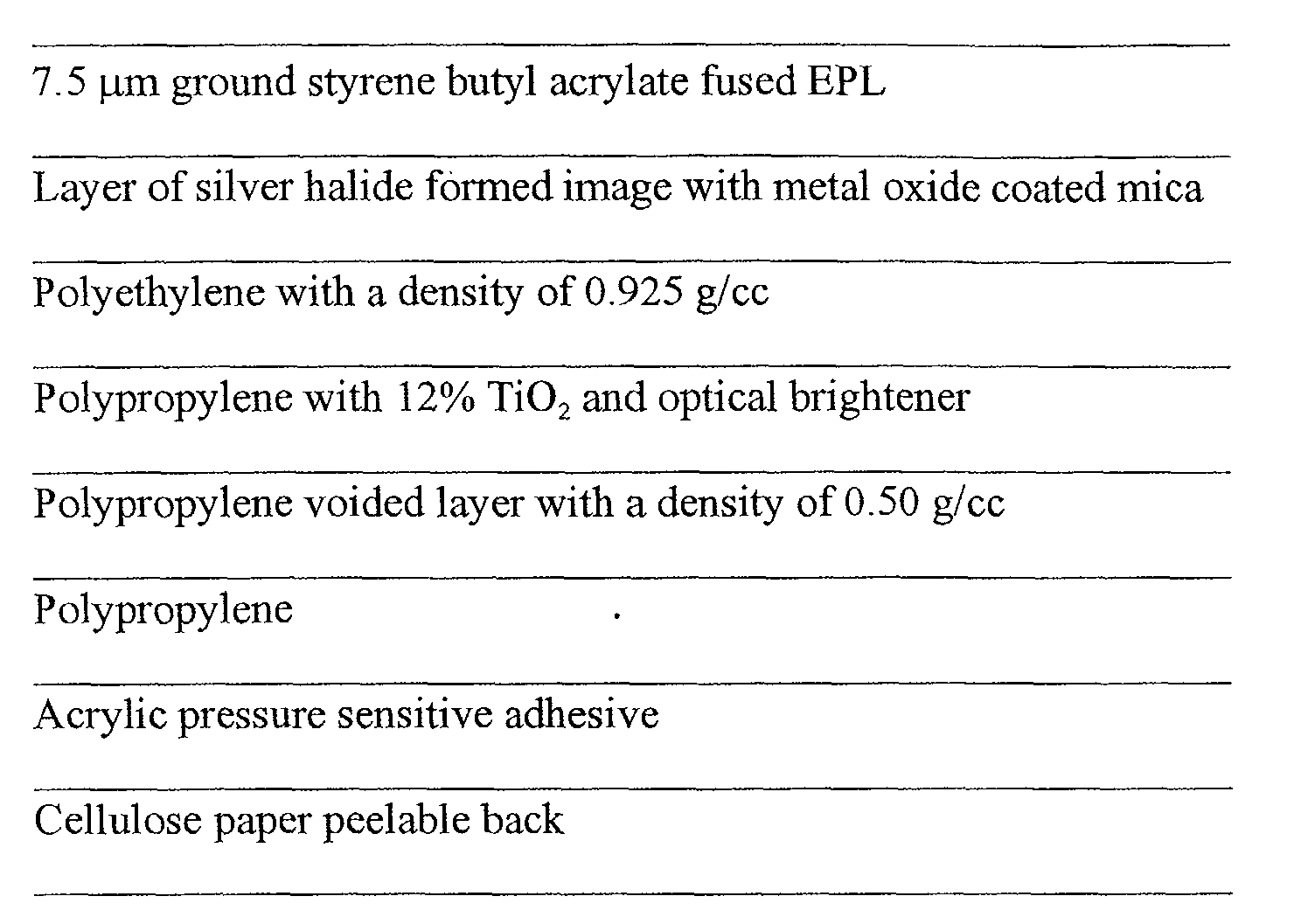
Fig. 1 is an illustration of the structure of an imaged nacreous
silver halide pressure sensitive label on a paper liner.
DETAILED DESCRIPTION OF THE INVENTION
The invention has numerous advantages over prior art printed
pressure sensitive labels. The reflective materials of the invention provide a
photographic label with a nacreous appearance while maintaining efficient
reflection of light, sharpness, and photographic speed. Maintaining image
sharpness and whiteness is important, as consumers expect silver halide images to
be high in quality. Further, maintaining printing speed is critical for efficient
photographic processing, as a significant loss in printer speed could increase the
cost of labels. Because the silver halide formed imaging layers of the invention
are semi transparent, the imaging layers can be used in combination with a
nacreous base or coated compared to pigmented printing inks utilized for printing
of packaging labels, which do not allow the effective use of a nacreous base or
coating.
The nacreous imaging materials of the invention provide an
eye-catching appearance that make them particularly desirable in imaging
applications that require obtaining the attention of the consumer. One example
includes display materials that are intended to communicate an advertising
message to people in a public setting such as a bus stop, train station, or airport.
The nacreous images are differentiated in look from prior art materials and, thus,
provide the pop and sizzle that can catch the consumer's attention. By providing
the nacreous image with a pressure sensitive adhesive, the tough, durable nacreous
image can be applied to various surfaces, which is particularly desirable for the
youth market.
Photographic nacreous labels of the invention utilized in packaging
markets enable a differentiated look and consumer appeal on store shelf. The
utilization of the thin, flexible, and tough silver halide materials results in a
packaging material having many superior properties. The packaging materials of
the invention have a depth of image unsurpassed by existing packaging materials.
The packaging materials of the invention may be utilized with a variety of
packaging materials that are suitable pressure sensitive labeling, such as shampoo
bottles, perfume bottles, and film boxes. The packaging materials of the
invention, while having the advantage of superior image, are available on thin
base materials which are low in cost while providing superior opacity and
strength. The packaging materials of the invention, as they may be imaged by
flash optical exposure or digital printing, have the ability to be formed in short
runs and to be rapidly switched from one image to the next without delay.
The terms as used herein, "top", "upper", "emulsion side", and
"face" mean the side or toward the side of a photographic member bearing the
imaging layers. The terms "bottom", "lower side", and "back" mean the side or
toward the side of the photographic member opposite from the side bearing the
photosensitive imaging layers or developed image. Nacreous appearance is a
pearly, luster, iridescent, metallic sheen. A characteristic property of a nacreous
appearance is an angular dependence of viewing angle.
For the packaging material of the invention, at least one layer
consisting of a nacreous pigment is located between the top of the imaging layers
and the bottom of the pressure sensitive adhesive layer. By locating a nacreous
pigment between the top of the imaging layer and the bottom of the adhesive
layer, the silver halide formed image appears nacreous and thus has great value as
a packaging label. In the invention a photographic element comprises nacreous
pigments. Such a photographic label element has a unique capability to preserve
images with special luster sheen that is not available in traditional printed labels
or commercial displays that utilize pigmented inks. A preferred embodiment of
this invention comprises nacreous material in a photographic layer which is on a
white reflective label base. The white reflective label base provides an excellent
surface and background while viewing labels. In particular, it is desirable to have
a white reflective base that has an L* of greater than 92. L* greater than 92 are
desirable because they provide good contrast to the image and are pleasing to the
consumer. L* or lightness and opacity were measured for using a Spectrogard
spectrophotometer, CIE system, using illuminant D6500.
In a further embodiment of this invention the nacreous pigments
are added to the polymer facestock. Addition to the facetock provides a unique
appearance to the silver halide packaging labels as the nacreous pigments are
aligned during the orientation process utilized in the manufacture of label
facestock materials of this invention. Alignment of the nacreous pigment during
orientation has been shown to provide multiple reflection planes for the formation
of the nacreous image while using approximately 50% less than cast coated
facestock materials. Further, the nacreous pigment addition to the facestock and
the silver halide imaging layers provides a two tiered appearance as nacreous
pigment in the imaging layers tends to be more scattering (as the pigments tend to
have a random orientation) and the nacreous pigments in the facestock tend to be
more specular as they are oriented. The two tiered appearance is the result of the
nacreous of the nacreous pigment in the emulsion and nacreous pigment in the
facestock.
Because the nacreous imaging element is directed at labeling of
packages, the color gamut of the nacreous pigment is expanded beyond the color
gamut of traditional imaging methods that typically utilize pigments that are white
and reflecting and blue tints that off set the native yellowness of the gelatin
binder. The preferred color of the nacreous pigments for the invention includes
colors that are within the following range; a* from -20 to +20 and b* from -20 to
+20 (utilizing CIELAB color space). Nacreous pigments is this range provide
several color positions that have significant commercial value. An example is a
oxide coated mica pigment that has an a* value of +18 and a b* value of -8 and a
hue angle of 320 degrees. This nacreous pigment when applied to a pressure
sensitive label has a nacreous rose/red wine color that accentuates bottled red
wine.
For the purpose of this invention the photographic element
comprises silver halide emulsion. Said silver halide emulsion may comprise more
than one layer. It should also be noted that some layers may comprise light
sensitive silver halide materials, and other layers may not contain light sensitive
materials.
In this invention the photographic label element comprises
nacreous pigments. The element may have nacreous pigment in a layer that
comprises silver halide emulsion; that is, the nacreous pigment is in the same
layer or layers that have the light sensitive silver halide emulsion. After the silver
halide is exposed and processed, the nacreous pigment provides a source of
additional spectral reflection that provides a unique appearance to the image.
Since the silver halide emulsion has more than one layer, and in the case of color
emulsions there may be at least three or more layers each capable of capturing
light of a different wavelength, said nacreous pigment may be in one or more
layers. This will allow only certain colors or all colors to demonstrate the
nacreous appearance.
The term "nacreous" refers to a pearly, luster, and nacreous
appearance. This may include a metallic, lustrous, and somewhat iridescent
effect. The nacreous effect is the result of interference pigments that are platelet-like
in their structure. Typically these are elongated platelet-like structures of
silicate-based materials such as mica, feldspar, and quartz. These pigments tend
to cause specular and diffuse reflection, and they also transmit some light. The
use of nacreous pigments in the paint and printing industry are typically designed
to create a variety of eye-popping colors. These materials are typically coated
over dark black backgrounds to help accentuate the eye-popping optical effects.
Special metal oxide coatings are applied to mica particles in very thin layers.
This allows for some light to be refracted, while other light will transmit through
to the near transparent layers of the mica particle to be refracted at a slightly
different angle. Since these pigments are suspended in a binder polymer of yet
another refractive index, there are multiple light refractions that create a lustrous
appearance. In addition, the chemistry of the coating that is applied to the mica
particles may be varied to create various colors.
Metal oxide coatings that may be used in an embodiment of this
invention include titanium, iron, chromium, barium, aluminum, zinc, zirconium,
bismuth vanadate, nickel titanate, chromium titanate, lead, and others. While
these produce some exciting colors in the field of photography and imaging,
traditional print materials have a white background. Additionally, it should be
noted that the thickness of the metal oxide coating on the mica may also impact
the color. In a preferred embodiment of this invention the metal oxide coating on
the mica particles may comprise titanium, aluminum, and/or barium. These
materials are preferred because it is desirable to have a more traditional white
background that can be achieved with these materials. The most preferred metal
oxide is titanium because of its superior whiteness. Typically it is important to
control the thickness of the metal oxide coating to less than 120 nanometers to
achieve a blue white appearance.
With nacreous pigments used in imaging application, it is desirable
to have non-uniform platelet thickness and small particles to create a white
nacreous appearance. In imaging applications where a different look is desirable,
the use of thicker particles and more uniform spacing of platelets to each other
creates a color interference that is more characteristic of mother-of-pearl. In
general, the lustrous pigments referred to in this invention are pigments that
consist of flat mica platelets coated with titanium dioxide or other metal oxides.
They are irregular in shape and may vary in thickness from 0.1 to 0.5
micrometers, although some individual particles may be thicker. The particles
may have a length of up to 500 micrometers. The coating applied to the mica
particles should be controlled in thickness, but the overall thickness is one
parameter that controls the overall color appearance. Each transparent coating
helps to create the lustrous or pearlescent effect.
The particle of these pigments influences the perceived texture of
the pearl luster effect and adds a new dimension of beauty and quality to the
image. The coating may be colored with other compatible transparent pigments
and dyestuffs. Metallic effects can be simulated by adding small amounts of
carbon black with some silvery white pigments. The color seen is different than
color pigments and dyes in that the color and lustrous iridescence is produced by
light interference and not absorption or reflection of light. This is a suprisingly
unique attribute to the field of silver halide photography and imaging. With the
use of nacreous pigments there are many refractive interface that can produce a
unique appearance to an imaging element. A light ray striking a layer containing
nacreous platelets must pass through a substantially transparent layer of relatively
lower refractive index binder polymer surrounding the platelet, and then the ray is
then partially reflected by the metal oxide coating on the surface. The remaining
part passes into the metal oxide coating layer and is again reflected as it exits the
layer at the interface with the mica particle. Since the coating is very thin and the
mica platelets are substantially transparent, the remaining light has many
opportunities to be reflected at different angles. This helps to provide the luster
nacreous appearance, as well as to add a three-dimensional quality to the image.
The resulting color effect that is produced depends on the light reflection from the
interfaces, as well as the type of coating on the mica particles. The multiple
interfaces cause the reflected light to be slightly out of phase. It should also be
noted that the color varies based on the angle of illumination and that an
iridescence effect can be seen.
Control of this effect is desirable depending on the effect that
needs to be conveyed by the image. As noted above the thickness and type of the
coating on the mica particles are factors that need to be considered. In addition the
particle size can also be used to control the effect. For use in a photographic
element it is desirable to have a smooth surface. To achieve this, a small particle
is best but the layer thickness of the binder polymer in which the pigments are
suspended may also be increased as well as applying clear overcoats. Larger
particles are desirable when a bold effect with visual impact is desired. The
nacreous effect can be changed by adjusting the particle size, metal oxide coating
thickness and type, as well as the concentration of the pigment. In general, low
pigmentation levels are better at producing a three-dimensional effect. This effect
may be enhanced by applying a thick clear layer over the top of the nacreous
pigments. When a more metallic sheen is desired, higher pigmentation levels are
best. It should also be noted that different effects may be achieved by adding
other transparent pigments and dyes in the layers. Since light sensitive
photographic layers produce dye couplers that are semitransparent and typically
do not contain pigment particles; they are uniquely positioned to be able to create
synergistic effects with the nacreous pigments.
The nacreous pigments are relatively stable and generally resistant
to alkali and acids, as well as high temperature. They can be dispersed in most
carrying (binder polymer) media. Since the particles are substantially transparent,
the use of a carrying media that is also transparent provides the maximum effect.
If a more translucent carrying media is used, more nacreous pigment may be
needed to achieve the same level of nacreous appearance.
In some applications it may be desirable to also have a nacreous
pigment that is also conductive. 'This has some unique advantages in the area of
photography that uses light sensitive layers. Static accumulation and discharge
can result in a fogged layer. Being able to provide a conductive path that helps to
prevent the charge from building up is an important element for imaging media.
This not only helps prevent light fogging of light sensitive layer, but also allows
sheets to slide over each other and various equipment parts without static buildup
or cling of one sheet to another. This type of pigment is also a means of adding
conductivity to the emulsion side of a photographic element. Conductive
nacreous pigments consist of an inner core of platelet mica that is coated with
materials such as TiO2, SiO2 and further coated with an outer dense layer of
conductive, inorganic mixed metal oxide. A typical conductive material is
antimony-doped tin dioxide. The elongated particles of mica are useful in
providing a conductive pathway when particles are touching.
The origin of the beauty of a genuine pearl has been well
documented. It is known that its luster and color come from the multiple smooth
concentric layers of nacre, i.e., calcium carbonate layer, organic constituent
(conchiolin) layer. Each of these layers partially reflects and transmits light.
Hence, a sense of depth and luster is observed in the reflection. Pigments that try
to simulate the visual effect of a pearl are called as pearlescent or nacreous
pigments. The first nacreous pigment was the natural pearl. The commercial
grades of nacreous pigments are made of thin transparent platelets of high
refractive index. These pigments are so designed that multiple reflections and
transmissions occur and, as a result, a sense of depth is obtained in the overall
reflected image. The characteristics of the pigment determine whether color is
produced by light interference (specifically called as interference pigments) or no
color is produced (called as white nacreous pigments).
Some of the earliest pearlescent pigments were the plate-like
bismuth oxychloride crystals, and basic lead carbonate. These pigments reflect
light similar to a pearl essence crystal. Due to toxicity of lead, bismuth
oxychloride (BiOCI) crystals have seen an increased use in the marketplace.
BiOCl is generally crystallized from solution into smooth, thin platelets which
have a particle size ranging from 5 µm to 15 µm.
The other commonly used pearlescent pigments are those made
from mica coated with either titanium dioxide (US 4,040,859), iron oxide (US
3,087,829), zirconium dioxide (US 3,087,828), or other high refractive index
materials. Mica is used because it is transparent to light and can be cleaved into
extremely thin flakes. Examples of mica suitable for pearlescent pigments are
muscovite, paragonite, phlogopite, biotite, and lepidolite. The mica platelets are
then coated with a thin single layer or multiple layers of high refractive index
inorganic oxide. The reflection efficiency depends to a large extent on the
refractive index difference between the mica platelet and the inorganic oxide
coating. This layered structure enables it to function like a pearlescent pigment.
The oxide coating provides the optical effects like luster, interference reflection
color (if oxide coating is sufficiently thick) and absorption color (if the oxide
contains color material). The size of the mica particle also plays an important role
in determining the final reflected image. The weight of the mica in the pigment
usually lies between 40% and 90% and most usually in the range of 60% and
80%. If titanium dioxide is used as the coating and its coating thickness is
increased, then an iridescence effect (color) is observed. The dimensions of
pearlescent pigments used in this invention may be between 5 µm and 400 µm
and preferably between 5 µm and 100 µm because particles less than 5 µm are not
very efficient in creating the nacreous appearance, while particles greater than 100
µm progressively get rougher. Excessive roughness on the surface tends to shut
down the nacreous appearance. The thickness of the pigment is preferably
between 0.1 µm and 0.6 µm and more preferably between 0.2 µm and 0.4 µm.
Particles less than 5 µm or less than 0.2 µm typically do not have sufficiently
higher nacreous appearance, while particles greater than 400 µm in length or 0.6
µm in width typically are very large and tend to create roughness which starts to
shut down the nacreous effect.
Other optically variable pigments that are suitably used are silicon
oxide coated with thin layers of aluminum (5 nm and 10 nm) or titanium dioxide,
and magnesium fluoride crystals coated with chromium have also been used.
These pigment structures have been highlighted in US 3,438,796. New optically
variable pigment structures based on coated platelet like metallic substrates have
been disclosed in US 5,364,467 and US 5,662,738. US 5,976,511 discloses
pigments composed of barium sulfate particles and coated with zinc oxide, cerium
oxide, or titanium dioxide which have a pearly luster.
The photographic label elements of this invention may utilize an
integral emulsion bonding layer that allows the emulsion to adhere to the support
materials during manufacturing and wet processing of images without the need for
expensive subbing coatings. The preferred emulsion bonding layer comprises
polyethylene with a density between 0.88 and 0.94 g/cc. Polyethylene in this
density range has been shown to provide excellent adhesion to gelatin when the
polyethylene is corona discharge treated prior to coating with gelatin based
adhesion layers.
In a preferred additional embodiment the nacreous pigment may be
in a layer of the photographic label element that is free of silver halide emulsion.
It is common knowledge that photographic emulsions have multiple layers in
which the light sensitive layers are separated by an interlayer and furthermore
have a size overcoat in the topmost position that are not light sensitive. In this
embodiment the nacreous material is located above or below a layer or layers that
further comprise silver halide. This embodiment is preferred because the
nacreous pigments do not have to be fully compatible with the silver halide
emulsion and are, therefore, less likely to interfere with image development or
keeping. The nacreous appearance is still present after the image is formed and
developed. In an additional embodiment the nacreous pigment is in a layer on the
surface or adjacent to the surface of said photographic label element. In this
embodiment the reflected light of the exposed and developed image creates a
nacreous appearance to the image. In yet another preferred embodiment of said
photographic label element, said nacreous pigment is in a layer below said
bottommost layer comprising silver halide. This embodiment is preferred because
light is allowed to expose the silver halide as it passes through the layers, but the
secondary light that bounces back from the base is impacted by the nacreous
pigments. This provides a very soft nacreous appearance to the image.
In a preferred embodiment of this invention the nacreous pigments
comprises mica. Coated mica is preferred because it has a platelet structure that,
when coated with metal oxides, has a nacreous appearance that provides a very
unique look to an image which is appealing. Furthermore, said mica may be
easily dispersed and coated in a layer or layers that comprise silver halide
emulsion, as well as layers that are free of or at least substantially free of silver
halide emulsion. For the purpose of this invention the term "mica" refers to
nacreous materials and includes mica, feldspar, quartz, silicates, modified mica,
and mica that has been coated with a metal oxide, mica coated with materials that
have a difference in refractive index greater than 0.2. The mica material may be a
translucent organic and/or inorganic materials and may have a nacreous effect
when viewed from different angles.
In other suitable embodiments of this invention, nacreous pigments
may be incorporated in either or both the light sensitive emulsion layers and the
size overcoat used to protect the photographic label from handling damage or
water in the case of a soap label. Nacreous pigments have been shown to be an
effective means to filter UV radiation. This has significant advantage to minimize
photographic dye fade.
In an additional embodiment of this invention, said photographic
label element comprising a nacreous pigment has an electrical resistant of less
than 1013 log ohms per square. Electrical resistance less than 1013 is desirable to
prevent static buildup and discharge that can cause the light sensitive layer to fog.
In yet an additional embodiment of this invention, said
photographic label element comprises nacreous pigment that has a mean particle
size between 0.5 and 50 micrometers. Particles less than 0.5 micrometer in size
tend not to have a sufficient platelet structure to create a strong nacreous
appearance. It should be noted that small particle sizes in the preferred range
have less of a scattering impact on the light sensitive layers and, therefore, have
minimal interference with the exposure of the silver halide and sharpness. The
smaller particle sizes are further desirable with the relatively thin layer of a
photographic emulsion to minimize roughness that can cause excessive light
scattering. Larger particles are desirable to get more efficient nacreous
appearance, but particles greater than 50 micrometers are very rough and difficult
to incorporate in or around light sensitive layers. Typically the large particles
should be coated in layers several times thicker than the particle.
In a preferred embodiment of this invention said photographic
label element has a b* less than 10. A b* less than 10 is desirable for
photographic print material because of the customer traditional expectation of a
white appearing print. Furthermore, b* less than 10 provides excellent contrast to
other colors. There are many color shades of white. Blue whites are desirable to
make the whites look whiter, while less blue or more yellow whites are desirable
for warmer tones images. Other color tints may be used for other shades of white,
while optical brighteners may be used in conjunction with the nacreous pigments
to make the whites more blue appearing. Nacreous pigments with colors other
than white may be used to create special effects or color schemes.
In this invention the nacreous pigments may comprises between
0.5 and 1000 mg/m2 of the photographic label element. Nacreous pigment levels
below 0.5 mg/m2 are difficult to detect and generally do not have a nacreous
impact. Nacreous pigment levels above 1000 mg/m2 do not have a proportional
improved nacreous appearance for the additional expense. Furthermore, if the
level is above 1000 mg/m2, the nacreous pigments tend to stack more vertically
and their impact is decreased. In a preferred embodiment of this invention, said
nacreous pigments are present in the amount between 7 and 250 mg/m2. Below 7
mg/m2 the nacreous appearance is more difficult to see, while levels above 250
mg/m2 do not have a significantly improved nacreous appearance for the
additional expense. When nacreous pigments are incorporated in and/or above
silver halide layers, the amount of the nacreous pigment should be kept low to
minimize interference with the image exposure. Higher level in the preferred
range tend to have a stronger nacreous appearance which is desirable in certain
applications for display or youth markets where a different look is valued. In the
preferred embodiment of this invention, the nacreous pigment should comprise
between 0.1 to 9% by volume of the photographic emulsion. Levels below 0.1 %
have minimal nacreous appearance, while levels above 9% cause excessive
stacking of the platelets which tends to interfere with the nacreous appearance.
Additionally it is desirable to have the nacreous pigments as the only pigment in a
substantial clear polymer. The inclusion of other solid particles tends to cause
more light scattering and, therefore, reduces the nacreous effect.
Nacreous or pearlescence appearing media has shown to be highly
desirous from a commercial standpoint. Incorporation of nacreous pigments in a
substantially transparent substrate or construction of composite materials
containing localized voiding of a specific geometry, orientation, and formulation
can produce both "colored" nacreous and "white" nacreous media. For both
types, this nacrescence results in perceived depth, luster, and a metallic
appearance. Correct measurement of these materials is required for robust design.
For both pigment and voiding methods, "white" nacreous luster is
a function of the orientation, as well as the spacing and composition of the
materials. The luster and depth appearance of the media are mainly due to the
reflected light that reaches the eye. Both pigments and voids that provide a
nacreous appearance function as substantially transparent platelets oriented
parallel to each other. This results in depth as each platelet reflects some of the
incident light while transmitting the rest. Any imperfections due to surface
defects or platelet or void orientation misalignments will cause the light to be
scattered in a non-specular direction, and will degrade the nacreous appearance of
the material.
In addition, the natural tendency for randomness in regards to
platelet or void alignment and spacing will render the media incapable of
producing color by light interference. Any color produced by one alignment and
spacing will have a tendency to be counteracted by other encountered alignments
and spacing. However, gross geometric misalignments of the platelets or voids
will also result in less than desirable functionality, and a method of measuring this
defect is required as well.
FLOP is a test method used to measure the nacreous quality of
materials of interest. 45-degree incident light is collected at 10, 45, and 110
degrees from the specular reflection angle. The spectrophotometric output, e.g.,
CIE L* (L1*, L2*, L3* respectively) is used as follows:
FLOP = 15 (L1*-L3*)1.11/L2*0.86
whereby FLOP values between less than 10 have no nacreous appearance and
FLOP values greater than 10 are indicative of a nacrescent appearance.
Furthermore, quality monitoring of these nacreous materials, when
combined with one or more semitransparent color forming dyes layers, places
limitations on the usefulness of measurements taken with typically found
reflection densitometers having 0/45 geometry. This is due to the angular
dependency of these media. This angular viewing dependency of the media and
the inherent randomness of the structure will result in errors "reading out " the
dye formed due to the variability of the media at any one collection angle. These
highly specular and translucent materials will reflect some light in angular
dependent non-specular directions as well. It has been found that although
incident light and collection at 0/45 will allow for a prediction of density
minimum versus FLOP, these values are no longer predictive, as density increases
from density minimum to density maximum as color dye forming layers are added
to the media.
This can be explained as a function of the dye density. As density
increases, the ability for multiple reflections through the media decreases. As the
reflection passes approach one, the nacreous look will no longer be apparent.
Spectrogoniometric measurements can be employed to measure the
media at various angles, but spectrogoniometric readings are tedious and the
apparatus is expensive. An alternative for quality monitoring purposes to assess
the amount of color forming layers coated and subsequently processed would be
useful. During a color photographic coating operation, the need to reduce
inherent manufacturing variability of color forming coupler levels is required and
this data collection by conventional reflection 0/45 densitometry is impeded by
the natural variability found in the nacreous media. Slight changes in the
reflective properties of the base media will result in more or less light reaching the
densitometer which, in turn, can result in an erroneous readout of the formed dye.
One such method to provide correct assessment during a coating
operation would be to remove the nacreous properties of the media. This can be
accomplished by collecting light from the prepared sample at a grazing angle that
would minimize the nacreous layer contributions. Diffuse 8 degree sphere optical
geometry handheld spectrophotometers have been shown to meet this need.
In a preferred embodiment of this invention, said photographic
label element comprising nacreous pigments wherein said element has a flop
measurement of between 2 and 65. Flop measurements below 2 have little or no
nacreous appearance, while flop measurements above 65 are difficult to achieve
with nacreous pigments.
In a further embodiment of this invention, the photographic label
element further comprises a white reflective base that further comprises a surface
roughness of less than 0.8 micrometer. Reflective bases greater than 0.8
micrometers tend to exhibit a roughness frequency that greatly reduces the
nacreous appearance. Bases with a roughness of less than 0.8 micrometers are
generally glossy in overall appearance which tends to maximize the nacreous
appearance in an imaging print.
In a preferred embodiment of this invention, the photographic label
element comprising a nacreous pigment further comprises at least two exposed
and developed images that are folded with the image sides out, and the non-image
bearing sides are adhesively joined to form an album page. This embodiment is
preferred because it allows the nacreous appearance to be utilized with album
pages. Multiple images may be exposed and developed on one sheet of
photographic label element that contains nacreous pigment and then folded and
joined to form a convenient display. The page can then be punched and used as
part of an album page. In an additional embodiment, the exposed and developed
photographic label element may be folded using an apparatus for making an
album leaf from an image-bearing sheet. The sheet has an image bearing side and
a non-image bearing side, comprising:
The imaging elements of this invention are photographic label
elements, such as photographic display films and photographic paper, in which
the image-forming layer is a radiation-sensitive silver halide emulsion layer.
Such emulsion layers typically comprise a film-forming hydrophilic colloid. The
most commonly used of these is gelatin, and gelatin is a particularly preferred
material for use in this invention. Most of the nacreous pigments useful in this
invention are easily dispersed in gelatin. Additional dispersing aids may be used
with gelatin or other hydrophilic colloids. Most any aqueous dispersing aid
known in the art of pigments and paints may be useful. Useful gelatins include
alkali-treated gelatin (cattle bone or hide gelatin), acid-treated gelatin (pigskin
gelatin), and gelatin derivatives such as acetylated gelatin, phthalated gelatin, and
the like. Other hydrophilic colloids that can be utilized alone or in combination
with gelatin include dextran, gum arabic, zein, casein, pectin, collagen
derivatives, collodion, agar-agar, arrowroot, albumin, and the like. Still other
useful hydrophilic colloids are water-soluble polyvinyl compounds such as
polyvinyl alcohol, polyacrylamide, poly(vinylpyrrolidone), and the like.
The photographic label elements of the present invention can be
simple black-and-white or monochrome elements comprising a support bearing a
layer of light-sensitive silver halide emulsion, or they can be multilayer and/or
multicolor elements.
Color photographic label elements of this invention typically
contain dye image-forming units sensitive to each of the three primary regions of
the spectrum. Each unit can be comprised of a single silver halide emulsion layer
or of multiple emulsion layers sensitive to a given region of the spectrum. The
layers of the element, including the layers of the image-forming units, can be
arranged in various orders as is well known in the art.
In addition to emulsion layers, the photographic layer can contain
auxiliary layers conventional in photographic label elements, such as overcoat
layers, spacer layers, filter layers, interlayers, antihalation layers, pH lowering
layers (sometimes referred to as acid layers and neutralizing layers), timing layers,
opaque reflecting layers, opaque light-absorbing layers, and the like. The support
can be any suitable support as described in this invention. Typical supports
include polymeric films, polymeric film laminated to other polymeric, glass, and
the like. The important thing is to have translucent support that is both reflective
and diffusive. The light-sensitive silver halide emulsions employed in the
photographic label elements of this invention can include coarse, regular, or fine
grain silver halide crystals or mixtures thereof and can be comprised of such silver
halides as silver chloride, silver bromide, silver bromoiodide, silver
chlorobromide, silver chloroiodide, silver chorobromoiodide, and mixtures
thereof. The emulsions can be, for example, tabular grain light-sensitive silver
halide emulsions. The emulsions can be negative-working or direct positive
emulsions. They can form latent images predominantly on the surface of the
silver halide grains or in the interior of the silver halide grains. They can be
chemically and spectrally sensitized in accordance with usual practices. The
emulsions typically will be gelatin emulsions, although other hydrophilic colloids
can be used in accordance with usual practice. Details regarding the silver halide
emulsions are contained in and described in Research Disclosure, September
1994, Item 36544, Section I, published by Kenneth Mason Publications, Ltd.,
Dudley Annex, 12a North Street, Emsworth, Hampshire PO10 7DQ, ENGLAND
as well as Research Disclosure, Item 36544, September 1994, and the references
listed therein, as well as Research Disclosure, September 2000, Item 437013,
published by Kenneth Mason Publications, Ltd., Dudley Annex, 12a North Street,
Emsworth, Hampshire PO10 7DQ, ENGLAND.
The photographic silver halide emulsions utilized in this invention
can contain other addenda conventional in the photographic art. Useful addenda
are described, for example, in Research Disclosure, Item 36544, September 1994,
and Research Disclosure, September 2000, Item 437013, published by Kenneth
Mason Publications, Ltd., Dudley Annex, 12a North Street, Emsworth,
Hampshire PO10 7DQ, ENGLAND. Useful addenda include spectral sensitizing
dyes, desensitizers, antifoggants, masking couplers, DIR couplers, DIR
compounds, antistain agents, image dye stabilizers, absorbing materials such as
filter dyes and UV absorbers, light-scattering materials, coating aids, plasticizers
and lubricants, and the like.
Depending upon the dye-image-providing material employed in the
photographic label element, it can be incorporated in the silver halide emulsion
layer or in a separate layer associated with the emulsion layer. The dye-image-providing
material can be any of a number known in the art, such as dye-forming
couplers, bleachable dyes, dye developers and redox dye-releasers, and the
particular one employed will depend on the nature of the element, and the type of
image desired.
Dye-image-providing materials employed with conventional color
materials designed for processing with separate solutions are preferably dye-forming
couplers; i.e., compounds which couple with oxidized developing agent
to form a dye. Preferred couplers which form cyan dye images are phenols and
naphthols. Preferred couplers which form magenta dye images are pyrazolones
and pyrazolotriazoles. Preferred couplers which form yellow dye images are
benzoylacetanilides and pivalylacetanilides.
In a typical photographic label element which includes a size
overcoat, three light sensitive silver halide emulsion units with a color dye
forming, interlayers to separate the various light sensitive layers, and a pressure
sensitive label base. For the purpose of this invention, the nacreous comprising
materials may be added individually to each light sensitive emulsion and
interlayer or in more than one layer in any combination. Additionally the
nacreous materials may be added to a layer under the emulsion such as in the gel
sub or primer layer or as a separate additional layer.
In order to produce a pressure sensitive photographic nacreous
label, the liner material that carries the pressure sensitive adhesive, face stock and
silver halide imaged layers, the liner material must allow for efficient transport in
manufacturing, image printing, image development, label converting and label
application equipment. A nacreous label comprising a silver halide imaging layer,
a base and a strippable liner adhesively connected by an adhesive to said base,
wherein said base has a stiffness of between 15 and 60 millinewtons and an L* is
greater than 92.0, and wherein said liner has a stiffness of between 40 and 120
millinewtons is preferred. The photographic label of the invention is preferred as
the white, stiff liner allows for efficient transport through photographic printing
and processing equipment and improves printing speed compared to typical liner
materials that are brown or clear and have little contribution to secondary
exposure.
A peelable liner or back is preferred as the pressure sensitive
adhesive required for adhesion of the label to the package, can not be transported
through labeling equipment without the liner. The liner provides strength for
conveyance and protects the pressure sensitive adhesive prior to application to the
package. A preferred liner material is cellulose paper. A cellulose paper liner is
flexible, strong and low in cost compared to polymer substrates. Further, a
cellulose paper substrate allows for a textured label surface that can be desirable
in some packaging applications. The paper may be provided with coatings that
will provide waterproofing to the paper as the photographic element of the
invention must be processed in aqueous chemistry to develop the image. An
examples of a suitable water proof coatings applied to the paper are acrylic
polymer, melt extruded polyethylene and oriented polyolefin sheets laminated to
the paper. Paper is also preferred as paper contains moisture and salt which
provides antistatic properties that prevent static sensitization of the silver halide
image layers and has been shown to improve labeling in high speed labeling
equipment by reducing repellency between the package and the pressure sensitive
label. The preferred range of salt to be added to the cellulose paper is between
0.5% and 2.0% by weight of paper fiber. Below 0.4%, little improvement in
static dissipation has been observed. Above 2.5%, little improvement in static
reduction is observed and therefore is not cost justified.
Further, paper containing sizing agents, known in the photographic
paper art and disclosed in U.S. 6,093,521, provide resistance to edge penetration
of the silver halide image processing chemistry. An edge penetration of less than
8 mm is preferred as processing chemistry penetrated into the paper greater than
12 mm has been shown to swell causing die cutting problems when face stock
matrix is die cut and stripped from the liner. Also, penetration of processing
chemistry greater than 12 mm increases the chemistry usage in processing
resulting in a higher processing costs.
Another preferred liner material or peelable back is an oriented
sheet of polymer. The liner preferably is an oriented polymer because of the
strength and toughness developed in the orientation process. Preferred polymers
for the liner substrate include polyolefins, polyester and nylon. Preferred
polyolefin polymers include polypropylene, polyethylene, polymethylpentene,
polystyrene, polybutylene, and mixtures thereof. Polyolefin copolymers,
including copolymers of propylene and ethylene such as hexene, butene, and
octene are also useful. Polyester is most preferred, as it is has desirable strength
and toughness properties required for efficient transport of silver halide pressure
sensitive label liner in high speed labeling equipment.
In another preferred embodiment, the liner consists of a paper core
to which sheets of oriented polymer are laminated. The laminated paper liner is
preferred because the oriented sheets of polymer provide tensile strength which
allows the thickness of the liner to be reduced compared to coated paper and
oriented polymer sheet provides resistance to curl during manufacturing and
drying in the silver halide process.
The tensile strength of the liner or the tensile stress at which a
substrate breaks apart is an important conveyance and forming parameter. Tensile
strength is measured by ASTM D882 procedure. A tensile strength greater than
120 MPa is preferred as liners less than 110 MPa begin to fracture in automated
packaging equipment during conveyance, forming and application to the package.
The coefficient of friction or COF of the liner containing the silver
halide imaging layer is an important characteristic as the COF is related to
conveyance and forming efficiency in automated labeling equipment. COF is the
ratio of the weight of an item moving on a surface to the force that maintains
contact between the surface and the item. The mathematical expression for COF
is as follows:
COF = µ =(friction force/normal force)
The COF of the liner is measured using ASTM D-1894 utilizing a
stainless steel sled to measure both the static and dynamic COF of the liner. The
preferred static COF for the liner of the invention is between 0.2 and 0.6. As an
example, a 0.2 COF is necessary for coating on a label used in a pick-and-place
application. The operation using a mechanical device to pick a label and move it
to another point requires a low COF so the label will easily slide over the surface
of the label below it. At the other extreme, large sheets such as book covers
require a 0.6 COF to prevent them from slipping and sliding when they are piled
on top of each other in storage. Occasionally, a particular material may require a
high COF on one side and a low COF on the other side. Normally, the base
material itself, such as a plastic film, foil, or paper substrate, would provide the
necessary COF for one side. Application of an appropriate coating would modify
the image side to give the higher or lower value. Conceivably, two different
coatings could be used with one on either side. COF can be static or kinetic. The
coefficient of static friction is the value at the time movement between the two
surfaces is ready to start but no actual movement has occurred. The coefficient of
kinetic friction refers to the case when the two surfaces are actually sliding against
each other at a constant rate of speed. COF is usually measured by using a sled
placed on the surface. The force necessary at the onset of sliding provides a
measurement of static COF. Pulling the sled at a constant speed over a given
length provides a measure of kinetic frictional force.
The preferred thickness of the liner of the invention is between 75
and 225 micrometers. Thickness of the liner is important in that the strength of the
liner, expressed in terms of tensile strength or mechanical modulus, must be
balanced with the thickness of the liner to achieve a cost efficient design. For
example, thick liners that are high in strength are not cost efficient because thick
liners will result in short roll lengths compared to thin liners at a given roll
diameter. A liner thickness less that 60 micrometer has been shown to cause
transport failure in the edge guided silver halide printers. A liner thickness
greater than 250 micrometers yields a design that is not cost effective and is
difficult to transport in existing silver halide printers.
The liner of the invention preferably has an optical transmission of
less than 20%. During the printing of the silver halide labels, exposure light
energy is required to reflect from the face stock / liner combination to yield a
secondary exposure. This secondary exposure is critical to maintaining high level
of printing productivity. It has been shown that liners with an optical
transmission of greater than 25% significantly reduces the printing speed of the
silver halide label. Further, clear face stock material to provide the "no label
look" need an opaque liner to not only maintain printing speed, but to prevent
unwanted reflection from printing platens in current silver halide printers.
Since the light sensitive silver halide layers of the invention can
suffer from unwanted exposure from static discharge during manufacturing,
printing and processing, the line preferably has a resistivity of less than 1011
ohms/square. A wide variety of electrically-conductive materials can be
incorporated into antistatic layers to produce a wide range of conductivities.
These can be divided into two broad groups: (i) ionic conductors and (ii)
electronic conductors. In ionic conductors charge is transferred by the bulk
diffusion of charged species through an electrolyte. Here the resistivity of the
antistatic layer is dependent on temperature and humidity. Antistatic layers
containing simple inorganic salts, alkali metal salts of surfactants, ionic
conductive polymers, polymeric electrolytes containing alkali metal salts, and
colloidal metal oxide sols (stabilized by metal salts), described previously in
patent literature, fall in this category. However, many of the inorganic salts,
polymeric electrolytes, and low molecular weight surfactants used are water-soluble
and are leached out of the antistatic layers during processing, resulting in
a loss of antistatic function. The conductivity of antistatic layers employing an
electronic conductor depends on electronic mobility rather than ionic mobility and
is independent of humidity. Antistatic layers which contain conjugated polymers,
semiconductive metal halide salts, semiconductive metal oxide particles, etc. have
been described previously. However, these antistatic layers typically contain a
high volume percentage of electronically conducting materials which are often
expensive and impart unfavorable physical characteristics, such as color,
increased brittleness, and poor adhesion to the antistatic layer.
In a preferred embodiment of this invention the label has an
antistat material incorporated into the liner or coated on the liner. It is desirable
to have an antistat that has an electrical surface resistivity of at least 1011 log
ohms/square. In the most preferred embodiment, the antistat material comprises
at least one material selected from the group consisting of tin oxide and vanadium
pentoxide.
In another preferred embodiment of the invention antistatic
material are incorporated into the pressure sensitive adhesive layers. The
antistatic material incorporated into the pressure sensitive adhesive layer provides
static protection to the silver halide layers and reduces the static on the label
which has been shown to aid labeling of containers in high speed labeling
equipment. As a stand-alone or supplement to the liner comprising an antistatic
layer, the pressure sensitive adhesive may also further comprise an antistatic agent
selected from the group consisting of conductive metal oxides, carbon particles,
and synthetic smectite clay, or multi-layered with an inherently conductive
polymer. In one of the preferred embodiments, the antistat material is metal
oxides. Metal oxides are preferred because they are readily dispersed in the
thermoplastic adhesive and can be applied to the polymer sheet by any means
known in the art. Conductive metal oxides that may be useful in this invention
are selected from the group consisting of conductive particles including doped-metal
oxides, metal oxides containing oxygen deficiencies, metal antimonates,
conductive nitrides, carbides, or borides, for example, TiO2, SnO2, Al2O3, ZrO3,
In2O3, MgO, ZnSb2O6, InSbO4, TiB2, ZrB2, NbB2, TaB2, CrB2, MoB, WB, LaB6,
ZrN, TiN, TiC, and WC. The most preferred materials are tin oxide and
vanadium pentoxide because they provide excellent conductivity and are
transparent.
The flexible substrate of the invention contains the necessary
tensile strength properties and coefficient of friction properties to allow for
efficient transport and application of the images in high speed labeling equipment.
The substrate of the invention is formed by applying light sensitive silver halide
imaging layers of a flexible label stock that contains a pressure sensitive adhesive.
The imaging layers, face stock and pressure sensitive adhesive are supported and
transported through labeling equipment using a tough liner material. Because the
light sensitive silver halide imaging layers are vulnerable to environmental
solvents such as water, coffee and hand oils, an environmental protection layer is
preferably applied to the light sensitive silver halide imaging layers after image
development.
Illustrated in Fig. 1 is a silver halide pressure sensitive label with a
laminated paper liner. Developed silver halide image layer 10 is adhered to face
stock 12. Pressure sensitive layer 14 is adhered to face stock 12 containing
nacreous mica pigment on the side opposite the developed silver halide image
layers. Between pressure sensitive layer 14 and the laminated paper liner 18, is
silicone layer 16. During die cutting of the label, the silver halide layer 10, face
stock 12 and adhesive layer 14 are cut by a die. During application of the silver
halide label to a package, the silicone layer 16 and the laminated paper liner 18
are removed exposing pressure sensitive layer 14 and the photographic label of
the invention is adhered to a package by placing pressure sensitive adhesive layer
in contact with the package surface.
The environmental protection layer may consist of suitable
material that protects the nacreous image from environmental solvents, resists
scratching and does not interfere with the image quality. The environmental
protection layer is preferably applied to the photographic image after image
development because the liquid processing chemistry required for image
development must be able to efficiently penetrate the surface of the imaging
layers to contact the silver halide and couplers utilizing typical silver halide
imaging processes. The environmental protection layer would be generally
impervious to developer chemistry. An environmental protection layer where
transparent polymer particles are applied to the top most surface of the imaging
layers in the presence of an electric field and fused to the top most layer causing
the transparent polymer particles to form a continuous polymeric layer is
preferred. An electrophotographic toner applied polymer is preferred as it is an
effective way to provide a thin, protective environmental layer to the
photographic label that has been shown to withstand environmental solvents and
damage due to handling.
In another embodiment, the environmental protection layer is
coatable from aqueous solution, which survives exposure and processing, and
forms a continuous, water-impermeable protective layer in a post-process fusing
step. The environmental protection layer is preferably formed by coating polymer
beads or particles of 0.1 to 50 µm in average size together with a polymer latex
binder on the emulsion side of a sensitized photographic product. Optionally, a
small amount of water-soluble coating aids (viscosifiers, surfactants) can be
included in the layer, as long as they leach out of the coating during processing.
After exposure and processing, the product with image is treated in such a way as
to cause fusing and coalescence of the coated polymer beads, by heat and/or
pressure (fusing), solvent treatment, or other means so as to form the desired
continuous, water impermeable protective layer.
Examples of suitable polymers from which the polymer particles
used in environmental protection layer can be selected include poly(vinyl
chloride), poly(vinylidene chloride), poly(vinyl chloride-co-vinylidene chloride),
chlorinated polypropylene, poly(vinyl chloride-co-vinyl acetate), poly(vinyl
chloride-co-vinyl acetate-co-maleic anhydride), ethyl cellulose, nitrocellulose,
poly(acrylic acid) esters, linseed oil-modified alkyd resins, rosin-modified alkyd
resins, phenol-modified alkyd resins, phenolic resins, polyesters, poly(vinyl
butyral), polyisocyanate resins, polyurethanes, poly(vinyl acetate), polyamides,
chroman resins, dammar gum, ketone resins, maleic acid resins, vinyl polymers,
such as polystyrene and polyvinyltoluene or copolymer of vinyl polymers with
methacrylates or acrylates, poly(tetrafluoroethylene-hexafluoropropylene), low-molecular
weight polyethylene, phenol-modified pentaerythritol esters,
poly(styrene-co-indene-co-acrylonitrile), poly(styrene-co-indene), poly(styrene-co-acrylonitrile),
poly(styrene-co-butadiene), poly(stearyl methacrylate) blended
with poly(methyl methacrylate), copolymers with siloxanes and polyalkenes.
These polymers can be used either alone or in combination. In a preferred
embodiment of the invention, the polymer comprises a polyester or poly(styrene-co-butyl
acrylate). Preferred polyesters are based on ethoxylated and/or
propoxylated bisphenol A and one or more of terephthalic acid, dodecenylsuccinic
acid and fumaric acid as they form an acceptable environmental protection layer
that generally survives the rigors of a packaging label.
To increase the abrasion resistance of the environmental protection
layer, polymers which are cross-linked or branched can be used. For example,
poly(styrene-co-indene-co-divinylbenzene), poly(styrene-co-acrylonitrile-co-divinylbenzene),
or poly(styrene-co-butadiene-co-divinylbenzene) can be used.
The polymer particles for the environmental protection layer
should be transparent, and are preferably colorless. But it is specifically
contemplated that the polymer particle can have some color for the purposes of
color correction, or for special effects, so long as the image is viewable through
the overcoat. Thus, there can be incorporated into the polymer particle dye which
will impart color. In addition, additives can be incorporated into the polymer
particle which will give to the overcoat desired properties. For example, a UV
absorber can be incorporated into the polymer particle to make the overcoat UV
absorptive, thus protecting the image from UV induced fading or blue tint can be
incorporated into the polymer particle to offset the native yellowness of the
gelatin used in the silver halide imaging layers.
In addition to the polymer particles which form the environmental
protection layer there can be combined with the polymer composition other
particles which will modify the surface characteristics of the element. Such
particle are solid and nonfusible at the conditions under which the polymer
particles are fused, and include inorganic particles, like silica, and organic
particles, like methylmethacrylate beads, which will not melt during the fusing
step and which will impart surface roughness to the overcoat.
The surface characteristics of the environmental protection layer
are in large part dependent upon the physical characteristics of the polymer which
forms the toner and the presence or absence of solid, nonfusible particles.
However, the surface characteristics of the overcoat also can be modified by the
conditions under which the surface is fused. For example, the surface
characteristics of the fusing member that is used to fuse the toner to form the
continuous overcoat layer can be selected to impart a desired degree of
smoothness, texture or pattern to. the surface of the element. Thus, a highly
smooth fusing member will give a glossy surface to the imaged element, a
textured fusing member will give a matte or otherwise textured surface to the
element, a patterned fusing member will apply a pattern to the surface of the
element.
Suitable examples of the polymer latex binder include a latex
copolymer of butyl acrylate, 2-acrylamido-2-methylpropanesulfonate, and
acetoacetoxyethylmethacrylate. Other latex polymers which are useful include
polymers having a 20 to 10,000 nm diameter and a Tg of less than 60°C
suspended in water as a colloidal suspension.
Examples of suitable coating aids for the environmental protection
layer include any water soluble polymer or other material that imparts appreciable
viscosity to the coating suspension, such as high MW polysaccharide derivatives
(e.g. xanthan gum, guar gum, gum acacia, Keltrol (an anionic polysaccharide
supplied by Merck and Co., Inc.) high MW polyvinyl alcohol,
carboxymethylcellulose, hydroxyethylcellulose, polyacrylic acid and its salts,
polyacrylamide, etc). Surfactants include any surface active material that will
lower the surface tension of the coating preparation sufficiently to prevent edge-withdrawal,
repellencies, and other coating defects. These include alkyloxy- or
alkylphenoxypolyether or polyglycidol derivatives and their sulfates, such as
nonylphenoxypoly(glycidol) available from Olin Matheson Corporation or
sodium octylphenoxypoly(ethyleneoxide) sulfate, organic sulfates or sulfonates,
such as sodium dodecyl sulfate, sodium dodecyl sulfonate, sodium bis(2-ethylhexyl)sulfosuccinate
(Aerosol OT), and alkylcarboxylate salts such as
sodium decanoate.
The application of a ultraviolet polymerizable monomers and
oligomers to the outermost layer of the developed silver halide imaging layers and
subsequent radiation exposure to form a thin cross-linked protective layer is
preferred. UV cure polymers are preferred as they can easily be applied to the
outermost layer of the silver halide imaging layers and have been shown to
provide an acceptable protective layer for the silver halide label material.
Preferred UV cure polymers include aliphatic urethane, allyl methacrylate,
ethylene glycol dimethacrylate, polyisocyanate and hydroxyethyl methacrylate. A
preferred photoinitiator is benzil dimethyl ketal. The preferred intensity of
radiation is between 0.1 and 1.5 milliwatt/cm2. Below 0.05, insufficient cross
linking occurs yielding a protective layer that does not offer sufficient protection
for the labeling of packages.
The application of a pre-formed polymer layer to the outermost
surface of the developed label silver halide image to form an environmental
protection layer is most preferred. Application of a pre-formed sheet is preferred
because pre-formed sheets are tough and durable easily withstanding the
environmental solvents and handling forces applied to the silver halide imaged
label. Application of the pre-formed polymer sheet is preferable carried out
though lamination after image development. An adhesive is applied to either the
photographic label or the pre-formed polymer sheet prior to a pressure nip that
adheres the two surfaces and eliminates any trapped air that would degrade the
quality of the image.
The pre-formed sheet preferably is an oriented polymer because of
the strength and toughness developed in the orientation process. Preferred
polymers for the flexible substrate include polyolefins, polyester and nylon.
Preferred polyolefins include polypropylene, polyethylene, polymethylpentene,
polystyrene, polybutylene, and mixtures thereof. Polyolefin copolymers,
including copolymers of propylene and ethylene such as hexene, butene, and
octene are also useful. Polypropylene is most preferred, as it is low in cost and
has desirable strength and toughness properties required for a pressure sensitive
label.
The application of a synthetic latex to the developed silver halide
label image is another preferred environmental protection layer. A coating of
synthetic latex has been shown to provide an acceptable environmental protection
layer and can be coated in an aqueous solution eliminating exposure to solvents.
The coating of latex has been shown to provide an acceptable environmental
protection layer for the silver halide packaging label. Preferred synthetic latexes
for the environmental protection layer are made by emulsion polymerization
techniques from styrene butadiene copolymer, acrylate resins, and polyvinyl
acetate. The preferred particles size for the synethetic latex ranges from 0.05 to
0.15 µm. The synthetic latex is applied to the outermost layer of the silver halide
imaging layers by known coating methods that include rod coating, roll coating
and hopper coating. The synthetic latexes must be dried after application and
must dry transparent so as not to interfere with the quality of the silver halide
image.
The face stock material, or the flexible substrate utilized in this
invention on to which the light sensitive silver halide imaging layers are applied,
must not interfere with the silver halide imaging layers. Further, the face stock
material of this invention needs to optimize the performance of the silver halide
imaging system. Suitable flexible substrates must also perform efficiently in a
automated packaging equipment for the application of labels to various
containers. A preferred flexible substrate is cellulose paper. A cellulose paper
substrate is flexible, strong and low in cost compared to polymer substrates.
Further, a cellulose paper substrate allows for a textured label surface that can be
desirable in some packaging applications. The paper may be provided with
coatings that will provide waterproofing to the paper as the photographic element
of the invention must be processed in aqueous chemistry to develop the silver
halide image. An example of a suitable coating is acrylic or polyethylene
polymer.
Polymer substrates are another preferred face stock material
because they are tear resistant, have excellent conformability, good chemical
resistance and high in strength. Preferred polymer substrates include polyester,
oriented polyolefin such as polyethylene and polypropylene, cast polyolefins such
as polypropylene and polyethylene, polystyrene, acetate and vinyl. Polymers are
preferred as they are strong and flexible and provide an excellent surface for the
coating of silver halide imaging layers. Nacreous pigments are preferably added
to the oriented polymer layers of the facestock. By adding nacreous pigment to
the facestock, the nacreous pigments of the invention create multiple reflection
planes that provide a nacreous silver halide formed image. Nacreous pigments are
preferably added to the skin layers and/or the core layers to provide the desired
nacreous appearance. Nacreous pigments located adjacent to the imaging layers
are more effective than nacreous pigments added to the core. When nacreous
pigments are added to a oriented polymer skin layer or adjacent polymer layer,
they preferably added in an amount between 1 and 4% by weight. Less than
0.5%, the FLOP value of the image is less than 5, above 5% addition the
concentration of pigments begins to darken the oriented polymer sheet, reducing
the desired whiteness position of the sheet.
Biaxially oriented polyolefin sheets are preferred as they are low
in cost, have excellent optical properties that optimize the silver halide system
and can be applied to packages in high speed labeling equipment. Microvoided
composite biaxially oriented sheets are most preferred because the voided layer
provides opacity and lightness without the need for TiO2. Also, the voided layers
of the microvoided biaxially oriented sheets have been shown to significantly
reduce pressure sensitivity of the silver halide imaging layers. Microvoided
biaxially oriented sheets are conveniently manufactured by coextrusion of the
core and surface layers, followed by biaxial orientation, whereby voids are
formed around void-initiating material contained in the core layer. Such
composite sheets are disclosed in U.S. Patent Nos. 4,377,616; 4,758,462;
4,632,869 and 5,866,282. The biaxially oriented polyolefin sheets also may be
laminated to one or both sides of a paper sheet to form a label with greater
stiffness if that is needed.
The flexible nacreous polymer face stock substrate may contain
more than one layer. The skin layers of the flexible substrate can be made of the
same polymeric materials as listed above for the core matrix. The composite
sheet can be made with skin(s) of the same polymeric material as the core matrix,
or it can be made with skin(s) of different polymeric composition than the core
matrix. For compatibility, an auxiliary layer can be used to promote adhesion of
the skin layer to the core.
Voided biaxially oriented polyolefin nacreous sheets are a
preferred flexible face stock substrate for the coating of light sensitive silver
halide imaging layers. Voided films are preferred as they provide opacity,
whiteness and image sharpness to the image. "Void" is used herein to mean
devoid of added solid and liquid matter, although it is likely the "voids" contain
gas. The void-initiating particles which remain in the finished packaging sheet
core should be from 0.1 to 10 µm in diameter and preferably round in shape to
produce voids of the desired shape and size. The size of the void is also
dependent on the degree of orientation in the machine and transverse directions.
Ideally, the void would assume a shape which is defined by two opposed and edge
contacting concave disks. In other words, the voids tend to have a lens-like or
biconvex shape. The voids are oriented so that the two major dimensions are
aligned with the machine and transverse directions of the sheet. The Z-direction
axis is a minor dimension and is roughly the size of the cross diameter of the
voiding particle. The voids generally tend to be closed cells, and thus there is
virtually no path open from one side of the voided-core to the other side through
which gas or liquid can traverse.
The void-initiating material for the flexible face stock substrate
may be selected from a variety of materials and should be present in an amount of
about 5 to 50% by weight based on the weight of the core matrix polymer.
Preferably, the void-initiating material comprises a polymeric material. When a
polymeric material is used, it may be a polymer that can be melt-mixed with the
polymer from which the core matrix is made and be able to form dispersed
spherical particles as the suspension is cooled down. Examples of this would
include nylon dispersed in polypropylene, polybutylene terephthalate in
polypropylene, or polypropylene dispersed in polyethylene terephthalate. If the
polymer is preshaped and blended into the matrix polymer, the important
characteristic is the size and shape of the particles. Spheres are preferred and they
can be hollow or solid. These spheres may be made from cross-linked polymers
which are members selected from the group consisting of an alkenyl aromatic
compound having the general formula Ar-C(R)=CH2, wherein Ar represents an
aromatic hydrocarbon radical, or an aromatic halohydrocarbon radical of the
benzene series and R is hydrogen or the methyl radical; acrylate-type monomers
include monomers of the formula CH2=C(R')-C(O)(OR) wherein R is selected
from the group consisting of hydrogen and an alkyl radical containing from about
1 to 12 carbon atoms and R' is selected from the group consisting of hydrogen and
methyl; copolymers of vinyl chloride and vinylidene chloride, acrylonitrile and
vinyl chloride, vinyl bromide, vinyl esters having formula CH2=CH(O)COR,
wherein R is an alkyl radical containing from 2 to 18 carbon atoms; acrylic acid,
methacrylic acid, itaconic acid, citraconic acid, maleic acid, fumaric acid, oleic
acid, vinylbenzoic acid; the synthetic polyester resins which are prepared by
reacting terephthalic acid and dialkyl terephthalics or ester-forming derivatives
thereof, with a glycol of the series HO(CH2)nOH wherein n is a whole number
within the range of 2-10 and having reactive olefinic linkages within the polymer
molecule, the above-described polyesters which include copolymerized therein up
to 20 percent by weight of a second acid or ester thereof having reactive olefinic
unsaturation and mixtures thereof, and a cross-linking agent selected from the
group consisting of divinylbenzene, diethylene glycol dimethacrylate, diallyl
fumarate, diallyl phthalate, and mixtures thereof.
Examples of typical monomers for making the cross-linked
polymer void initiating particles include styrene, butyl acrylate, acrylamide,
acrylonitrile, methyl methacrylate, ethylene glycol dimethacrylate, vinyl pyridine,
vinyl acetate, methyl acrylate, vinylbenzyl chloride, vinylidene chloride, acrylic
acid, divinylbenzene, acrylamidomethyl-propane sulfonic acid, vinyl toluene, etc.
Preferably, the cross-linked polymer is polystyrene or poly(methyl methacrylate).
Most preferably, it is polystyrene, and the cross-linking agent is divinylbenzene.
Processes well known in the art yield nonuniformly sized void
initiating particles, characterized by broad particle size distributions. The
resulting beads can be classified by screening the beads spanning the range of the
original distribution of sizes. Other processes such as suspension polymerization,
limited coalescence, directly yield very uniformly sized particles.
The void-initiating materials may be coated with agents to
facilitate voiding. Suitable agents or lubricants include colloidal silica, colloidal
alumina, and metal oxides such as tin oxide and aluminum oxide. The preferred
agents are colloidal silica and alumina, most preferably, silica. The cross-linked
polymer having a coating of an agent may be prepared by procedures well known
in the art. For example, conventional suspension polymerization processes
wherein the agent is added to the suspension is preferred. As the agent, colloidal
silica is preferred.
The void-initiating particles can also be inorganic spheres,
including solid or hollow glass spheres, metal or ceramic beads or inorganic
particles such as clay, talc, barium sulfate, or calcium carbonate. The important
thing is that the material does not chemically react with the core matrix polymer
to cause one or more of the following problems: (a) alteration of the
crystallization kinetics of the matrix polymer, making it difficult to orient, (b)
destruction of the core matrix polymer, (c) destruction of the void-initiating
particles, (d) adhesion of the void-initiating particles to the matrix polymer, or (e)
generation of undesirable reaction products, such as toxic or high color moieties.
The void-initiating material should not be photographically active or degrade the
performance of the photographic element in which the biaxially oriented
polyolefin sheet is utilized.
The total thickness of the topmost skin layer of the polymeric face
stock substrate may be between 0.20 µm and 1.5 µm, preferably between 0.5 and
1.0 µm. Below 0.5 µm any inherent nonplanarity in the coextruded skin layer
may result in unacceptable color variation. At skin thickness greater than 1.0 µm,
there is a reduction in the photographic optical properties such as image
resolution. At thickness greater than 1.0 µm, there is also a greater material
volume to filter for contamination such as clumps or poor color pigment
dispersion.
Addenda may be added to the top most skin layer of the flexible
face stock substrate to change the color of the imaging element. For labeling use,
a white substrate with a slight bluish tinge is preferred. The addition of the slight
bluish tinge may be accomplished by any process which is known in the art
including the machine blending of color concentrate prior to extrusion and the
melt extrusion of blue colorants that have been preblended at the desired blend
ratio. Colored pigments that can resist extrusion temperatures greater than 320°C
are preferred, as temperatures greater than 320°C are necessary for coextrusion of
the skin layer. Blue colorants used in this invention may be any colorant that does
not have an adverse impact on the imaging element. Preferred blue colorants
include Phthalocyanine blue pigments, Cromophtal blue pigments, Irgazin blue
pigments, and Irgalite organic blue pigments. Optical brightener may also be
added to the skin layer to absorb UV energy and emit light largely in the blue
region. TiO2 may also be added to the skin layer. While the addition of TiO2 in
the thin skin layer of this invention does not significantly contribute to the optical
performance of the sheet, it can cause numerous manufacturing problems such as
extrusion die lines and spots. The skin layer substantially free of TiO2 is
preferred. TiO2 added to a layer between 0.20 and 1.5 µm does not substantially
improve the optical properties of the support, will add cost to the design, and will
cause objectionable pigments lines in the extrusion process.
Addenda may be added to the core matrix and/or to one or more
skin layers to improve the optical properties of the flexible substrate. Titanium
dioxide is preferred and is used in this invention to improve image sharpness or
MTF, opacity, and whiteness. The TiO2 used may be either anatase or rutile type.
Further, both anatase and rutile TiO2 may be blended to improve both whiteness
and sharpness. Examples of TiO2 that are acceptable for a photographic system
are DuPont Chemical Co. R101 rutile TiO2 and DuPont Chemical Co. R104 rutile
TiO2. Other pigments known in the art to improve photographic optical responses
may also be used in this invention. Examples of other pigments known in the art
to improve whiteness are talc, kaolin, CaCO3, BaSO4, ZnO, TiO2, ZnS, and
MgCO3. The preferred TiO2 type is anatase, as anatase TiO2 has been found to
optimize image whiteness and sharpness with a voided layer.
Addenda may be added to the flexible face stock substrate of this
invention so that when the biaxially oriented sheet is viewed from a surface, the
imaging element emits light in the visible spectrum when exposed to ultraviolet
radiation. Emission of light in the visible spectrum allows for the support to have
a desired background color in the presence of ultraviolet energy. This is
particularly useful when images are viewed outside as sunlight contains ultraviolet
energy and may be used to optimize image quality for consumer and commercial
applications.
Addenda known in the art to emit visible light in the blue spectrum
are preferred. Consumers generally prefer a slight blue tint to the density
minimum areas of a developed image defined as a negative b* compared to a
neutral density minimum defined as a b* within one b* unit of zero. b* is the
measure of yellow/blue in CIE (Commission Internationale de L'Eclairage) space.
A positive b* indicates yellow, while a negative b* indicates blue. The addition
of addenda that emits in the blue spectrum allows for tinting the support without
the addition of colorants which would decrease the whiteness of the image. The
preferred emission is between 1 and 5 delta b* units. Delta b* is defined as the b*
difference measured when a sample is illuminated with a ultraviolet light source
and a light source without any significant ultraviolet energy. Delta b* is the
preferred measure to determine the net effect of adding an optical brightener to
the top biaxially oriented sheet of this invention. Emissions less than 1 b* unit
cannot be noticed by most customers; therefore, is it not cost effective to add
optical brightener to the biaxially oriented sheet when the b* is changed by less
than 1 b* unit. An emission greater that 5 b* units would interfere with the color
balance of the images making the whites appear too blue for most consumers.
The preferred addenda is an optical brightener. An optical
brightener is a colorless, fluorescent, organic compound that absorbs ultraviolet
light and emits it as visible blue light. Examples include, but are not limited to,
derivatives of 4,4'-diaminostilbene-2,2'-disulfonic acid, coumarin derivatives
such as 4-methyl-7-diethylaminocoumarin, 1-4-Bis (O-Cyanostyryl) Benzol and
2-Amino-4-Methyl Phenol.
The voids provide added opacity to the flexible substrate. This
voided layer can also be used in conjunction with a layer that contains at least one
pigment from the group consisting of TiO2, CaCO3, clay, BaSO4, ZnS, MgCO3,
talc, kaolin, or other materials that provide a highly reflective white layer in said
film of more than one layer. The combination of a pigmented layer with a voided
layer provides advantages in the optical performance of the final image.
Voided layers of the flexible face stock substrate are more
susceptible than solid layers to mechanical failure, such as cracking or
delamination from adjacent layers. Voided structures that contain TiO2, or are in
proximity to layers containing TiO2, are particularly susceptible to loss of
mechanical properties and mechanical failure with long-term exposure to light.
TiO2 particles initiate and accelerate the photooxidative degradation of
polypropylene. The addition of a hindered amine stabilizer to at least one layer of
a multilayer biaxially oriented film and in the preferred embodiment in the layers
containing TiO2 and, furthermore, in the most preferred embodiment the hindered
amine is in the layer with TiO2, as well as in the adjacent layers, that
improvements to both light and dark keeping image stability are achieved.
The optical brightener may be added to any layer in the multilayer
coextruded flexible face stock substrate. The preferred location is adjacent to or
in the exposed surface layer of said sheet. This allows for the efficient
concentration of optical brightener.
When the desired weight percentage loading of the optical
brightener begins to approach a concentration at which the optical brightener
migrates to the surface of the support forming crystals in the imaging layer, the
addition of optical brightener into the layer adjacent to the exposed layer is
preferred. In prior art imaging supports that use optical brightener, expensive
grades of optical brightener are used to prevent migration into the imaging layer.
When optical brightener migration is a concern, as with light sensitive silver
halide imaging systems, the preferred exposed layer comprises polyethylene that
is substantially free of optical brightener. In this case, the migration from the
layer adjacent to the exposed layer is significantly reduced because the exposed
surface layer acts as a barrier for optical brightener migration allowing for much
higher optical brightener levels to be used to optimize image quality. Further,
locating the optical brightener in the layer adjacent to the exposed layer allows for
a less expensive optical brightener to be used as the exposed layer, which is
substantially free of optical brightener, prevents significant migration of the
optical brightener. Another preferred method to reduce unwanted optical
brightener migration in biaxially oriented sheets of this invention is to use
polypropylene for the layer adjacent to the exposed surface.
The coextrusion, quenching, orienting, and heat setting of the
flexible face stock substrate may be effected by any process which is known in the
art for producing oriented sheet, such as by a flat sheet process or a bubble or
tubular process. The flat sheet process involves extruding the blend through a slit
die and rapidly quenching the extruded web upon a chilled casting drum so that
the core matrix polymer component of the sheet and the skin components(s) are
quenched below their glass solidification temperature. The quenched sheet is then
biaxially oriented by stretching in mutually perpendicular directions at a
temperature above the glass transition temperature and below the melting
temperature of the matrix polymers. The sheet may be stretched in one direction
and then in a second direction or may be simultaneously stretched in both
directions. After the sheet has been stretched, it is heat set by heating to a
temperature sufficient to crystallize or anneal the polymers, while restraining to
some degree the sheet against retraction in both directions of stretching.
By having at least one nonvoided skin on the microvoided core, the
tensile strength of the flexible face stock substrate is increased and makes the
sheet more manufacturable. The higher tensile strength also allows the sheets to
be made at wider widths and higher draw ratios than when sheets are made with
all layers voided. Coextruding the layers further simplifies the manufacturing
process.
In another embodiment of the invention, a flexible nacreous label
base that is transparent is preferred. A transparent flexible label base is used to
provide a clear pressure sensitive label particularly useful for labeling applications
that allow the contents of the package to be viewed though the label. Examples
include wine bottle labeling, shampoo bottle labeling and beverage bottles that
utilize clear or colored glass. For this invention, "transparent" material is defined
as a material that has a spectral transmission greater than 90%. For a imaging
element, spectral transmission is the ratio of the transmitted power to the incident
power and is expressed as a percentage as follows; TRGB=10-D *100 where D is the
average of the red, green and blue Status A transmission density response
measured by an X-Rite model 310 (or comparable) photographic transmission
densitometer.
A flexible label base that has an optical transmission less than 20%
is preferred for most applications. Optical transmission less than 20% provide a
superior opaque silver halide pressure sensitive label that is highly reflective.
Opaque, highly reflective labels are useful for pressure sensitive labeling against a
background that is dark and would interfere with the quality of the image. An
example would be the labeling of a black package, a label base with optical
transmission greater than 20% would darken the image, resulting is a loss of low
density detail such as facial detail content.
A pressure sensitive photographic nacreous label adhesive is
utilized in the invention to allow the developed silver halide packaging label to be
adhered to the surface of the package typically utilizing high speed packaging
equipment. "Peelable separation" or "peel strength" or "separation force" is a
measure of the amount of force required to separate the silver halide label from
the package to which the label has been applied. The peel strength is the amount
of force required to separate two surfaces that are held together by internal forces
of the photographic label adhesive which consist of valence forces or interlocking
action, or both. Peel strength is measured using an Instron gauge and peeling the
sample at 180 degrees with a crosshead speed of 1.0 meters/min. The sample
width is 5 cm and the distance peeled is 10 cm in length.
A peelable photographic nacreous label adhesive is utilized to
allow the consumer to separate the label from the package. Separation of the
label from the package would allow for example, rebate coupons to be attached to
the package or used to for consumer promotions. For a peelable photographic
label adhesive, the preferred peel strength between the silver halide pressure
sensitive label and the package is no greater than 80 grams/cm. A peel strength
greater than 100 grams/cm, consumers would begin to have difficulty separating
the image from the package. Further, at peel strengths greater than 110
grams/cm, the force is beginning to approach the internal strength of paper
substrate, causing an unwanted fracture of the paper substrate before the
separation of the image.
Upon separation of the image from the substrate, the peelable
photographic nacreous label adhesive of this invention has a preferred
repositioning peel strength between 20 grams/cm and 100 grams/cm.
Repositioning peel strength is the amount of force required to peel the separated
image containing an photographic label adhesive from a stainless steel block at
23°C and 50% RH. At repositioning peel strengths less than 15 grams/cm, the
photographic label adhesive lacks sufficient peel strength to remain adhered to a
variety of surfaces such as refrigerators or photo albums. At peel strengths
greater than 120 grams/cm, the photographic label adhesive of this invention is
too aggressive, not allowing the consumer to later reposition the image.
The peelable photographic nacreous label adhesive of this
invention may be a single layer or two or more layers. For two or more
photographic label adhesive layers, one of the photographic label adhesive layers
preferentially adheres to the label base. As the image is separated from the
substrate, this allows the photographic label adhesive of this invention be adhered
to the label base for repositioning.
A substrate that comprises a release layer for a photographic label
adhesive that repositions is preferred. The release layer allows for uniform
separation of the photographic label adhesive at the photographic label adhesive
base interface. The release layer may be applied to the liner by any method
known in the art for applying a release layer to substrates. Examples include
silicone coatings, tetrafluoroethylene fluorocarbon coatings, fluorinated ethylenepropylene
coatings, and calcium stearate.
Suitable photographic label adhesives of this invention must not
interact with the light sensitive silver halide imaging system so that image quality
is deteriorated. Further, since photographic elements of this invention must be
photoprocessed, the performance of the photographic label adhesive of this
invention must not be deteriorated by photographic processing chemicals.
Suitable photographic label adhesive may be inorganic or organic, natural or
synthetic, that is capable of bonding the image to the desired surface by surface
attachment. Examples of inorganic photographic label adhesives are soluble
silicates, ceramic and thermosetting powdered glass. Organic photographic label
adhesives may be natural or synthetic. Examples of natural organic photographic
label adhesives include bone glue, soybean starch cellulosics, rubber latex, gums,
terpene, mucilages and hydrocarbon resins. Examples of synthetic organic
photographic label adhesives include elastomer solvents, polysulfide sealants,
theromplastic resins such as isobutylene and polyvinyl acetate, theromsetting
resins such as epoxy, phenoformaldehyde, polyvinyl butyral and cyanoacrylates
and silicone polymers.
For single or multiple layer photographic label adhesive systems,
the preferred photographic label adhesive composition is selected from the group
consisting of natural rubber, syntheic rubber, acrylics, acrylic copolymers, vinyl
polymers, vinyl acetate-, urethane, acrylate- type materials, copolymer mixtures
of vinyl chloride-vinyl acetate, polyvinylidene, vinyl acetate-acrylic acid
copolymers, styrene butadiene, carboxylated stryrene butadiene copolymers,
ethylene copolymers, polyvinyl alcohol, polyesters and copolymers, cellulosic and
modified cellulosic, starch and modified starch compounds, epoxies,
polyisocyanate, polyimides.
For single or multiple layer photographic label adhesive systems,
the preferred permanent photographic nacreous label adhesive composition is
selected from the group consisting of epoxy, phenoformaldehyde, polyvinyl
butyral, cyanoacrylates, rubber based photographic label adhesives,
styrene/butadiene based photographic label adhesives, acrylics and vinyl
derivatives. Peelable photographic label adhesives and permanent photographic
label adhesives may be used in combination in the same layer or in different
locations in the photographic support structure. An example of a combination
photographic label adhesive structure is a peelable photographic label adhesive
between the top biaxially oriented sheet and the base materials and a permanent
photographic label adhesive between the bottom biaxially oriented sheet and the
base material. In the case of a clear facestock, the adhesive preferably contains
nacreous pigments. By providing a clear facestock and nacreous pigments added
to the pressure sensitive adhesive layer, a nacreous photographic label is formed.
The silver halide imaging layers on a pressure sensitive substrate
preferably are applied to a variety of packages in automated labeling equipment.
Preferred package types are bottles, can, stand up pouch, box and a bag. The
packages may contain materials that require a package for sale. Preferred
materials that are packaged include liquids and particulate.
The silver halide packaging label of the invention preferably has a
thickness of less than 600 µm. A silver halide packaging label greater than 650
µm offers no significant improvement in either imaging quality or packaging label
performance. Further, transport through high speed packaging equipment is
difficult at a photographic label thickness greater than 650 µm and stripping the
photographic labels utilizing the Bernoulli method is difficult if the thickness of
the photographic label exceeds 700 µm.
The following is an example of a preferred nacreous opaque,
reflective silver halide pressure sensitive label structure that has an environmental
protection layer (EPL) applied to the outermost silver halide imaging layer. The
polyethylene and polypropylene layers are an integral biaxially oriented sheet, to
which the pressure sensitive adhesive and liner material are laminated prior to the
coating of the light sensitive silver halide imaging layers.
The following is another example of a preferred nacreous clear
silver halide pressure sensitive label structure that has an environmental protection
layer (EPL) applied to the outermost developed silver halide imaging layer. The
polyethylene and polypropylene layers are an integral biaxially oriented sheet, to
which the pressure sensitive adhesive and liner material are laminated prior to the
coating of the light sensitive silver halide imaging layers.
The following examples illustrate the practice of this invention.
They are not intended to be exhaustive of all possible variations of the invention.
Parts and percentages are by weight unless otherwise indicated.
EXAMPLES
In this example, nacreous pigment is added to several addition
points in a typical light sensitive silver halide emulsion. The nacreous pigment
containing imaging layers are applied to a base material suitable for labeling
packages. The addition of the nacreous pigment to the silver halide imaging
layers provides a nacreous appearance to the silver halide images. This example
will show the improvement in the FLOP value for the nacreous images compared
to a silver halide imaging layers that do not contain nacreous pigment.
Examples 1 to 10
Examples 1 to 10 include a three-color emulsion prepared as
described above. The light sensitive emulsion is coated on a photographic label
base material as described below:
Biaxially oriented polyolefin face stock:
A composite sheet polyolefin sheet (70 µm thick) (d = 0.68 g/cc)
consisting of a microvoided and oriented polypropylene core (approximately 60%
of the total sheet thickness), with a homopolymer non-microvoided oriented
polypropylene layer on each side of the voided layer; the void initiating material
used was poly(butylene terephthalate). The polyolefin sheet had a skin layer
consisting of polyethylene and a blue pigment. The polypropylene layer adjacent
the voided layer contained 8% rutile TiO2. The silver halide imaging layers were
applied to the blue tinted polyethylene skin layer.
Pressure sensitive adhesive:
Permanent solvent based acrylic adhesive 12 µm thick
Laminated paper liner:
A laminated liner that consisted of a cellulose paper core (80
micrometers thick) on to which a biaxially oriented sheet of polypropylene was
extrusion laminated to the back side utilizing LDPE resin. The backside oriented
polypropylene contained a roughness layer to allow for efficient transport in
photographic printing equipment. The roughness layer consisted of a mixture of
polyethylene and polypropylene immiscible polymers. The top side of the liner
was extrusion coated with LDPE for a silicone hold out. The cellulose paper
contained 8% moisture and 1% salt for conductivity. The total thickness of the
laminated paper liner was 128 micrometers and the stiffness was 80 millinewtons
in both the machine and cross directions. The paper liner was coated with a
silicone release coat adjacent to the extruded LDPE layer.
Structure of the base for the photographic packaging label material of the example
is as follows:
In the control and sample 7 there are no nacreous pigments in any
layer, while in Examples 1 to 6 and 8 to 10, a nacreous pigment was placed in at
least one layer. Table 4 below indicates the layer or layers that contained the
nacreous pigment. The nacreous pigment used was
Afflair 110, a fine particle
blue white pigment supplied by EM Industries, Inc. The pigment was dispersed
in gelatin using typical mixing. The gel lay down was approximately 39 g/m
2,
and the pigment weight was coated at 19.4 g/m
2 in each layer, and a second series
was coated at 190 g/m
2. The coating layer was dried and then an image was
exposed and developed using RA-4 chemistry.
Example 11 was the same as the other examples except that it
contains one extra layer in the emulsion coating in the bottommost position. This
layer contained approximately 45 g/m
2 of photo grade gelatin and 0.5% by
volume of the same nacreous pigment described above.
| Example | 1 | 2 | 3 | 4 | 5 | 6 | 7 | 8 | 9 | 10 | 11 | Control |
| SOC | Y | N | N | N | N | N | N | Y | Y | N | N | N |
| Red Sensitive Layer | N | Y | N | N | N | N | N | Y | N | Y | N | N |
| Interlayer | N | N | Y | N | N | N | N | Y | Y | N | N | N |
| Green Sensitive layer | N | N | N | Y | N | N | N | Y | N | Y | N | N |
| Interlayer | N | N | N | N | Y | N | N | Y | Y | N | N | N |
| Blue sensitive Layer | N | N | N | N | N | Y | N | Y | N | Y | N | N |
| Sub Coating | N | N | N | N | N | N | N | N | N | N | Y | N |
| Base |
| Y means the presence of a nacreous pigment. |
| N means no nacreous pigment |
After the image was exposed and developed, the samples were
viewed by visual examination under typical room light condition of a cool white
fluorescent light.
The visual examination results are tabulated in Table 5. When
viewing the samples, the print is rotated through an incident angle range from 0 to
70 degrees from the viewer. The viewer is looking for a rich lustrous appearance.
| Example | Nacreous Appearance Observed |
| 1 | Yes |
| 2 | Yes |
| 3 | Yes |
| 4 | Yes |
| 5 | Yes |
| 6 | Yes |
| 7 | No |
| 8 | Yes |
| 9 | Yes |
| 10 | Yes |
| 11 | Yes |
| Control | No |
As the data from Table 5 indicate, whenever the nacreous pigment
is present in a layer of the emulsion and even in the sub layer of the emulsion,
there is an observed nacreous appearance. The observation was a visual
assessment of the sample by reflected light. Because images in examples 1-10 all
had exhibited a nacreous appearance, they combine the high quality of silver
halide images with the eye catching nacreous appearance that has significant
commercial value as a packaging label. Further, because the silver halide imaging
layers containing nacreous pigment were applied to a label material, the nacreous
image can be applied to packages utilizing a variety of labeling techniques
including high speed labeling using the Bernoulli label stripping method. While
examples 1-6, 8 and 10 all exhibited a nacreous appearance, the control sample
(sample 11) did not have a nacreous pigment in the emulsion and thus did not
have a nacreous appearance.
While this example was directed at a silver halide nacreous image
formed by adding nacreous pigment to the silver halide imaging layers, nacreous
appearing label can also be result from addition of the nacreous pigment in the
facestock and/or pressure sensitive adhesive. The nacreous appearing label of the
invention may also be the result of nacreous pigment in the facestock and/or
adhesive in combination with nacreous pigment in the silver halide imaging
layers. In order for the nacreous materials of this example to be useful for
labeling packages, it is understood that the label need protection against
scratching, moisture and fingerprinting Methods known in the art for protecting
printed labels are useful for protecting the nacreous silver halide image layers.
Finally, while this invention is directed toward a nacreous pressure sensitive label
suitable for labeling packages, bottles and bags, the nacreous silver halide label of
the invention is useful for commercial display and sticker prints particularly for
the youth market.