EP1284402A2 - System and method of cooling - Google Patents
System and method of cooling Download PDFInfo
- Publication number
- EP1284402A2 EP1284402A2 EP02255605A EP02255605A EP1284402A2 EP 1284402 A2 EP1284402 A2 EP 1284402A2 EP 02255605 A EP02255605 A EP 02255605A EP 02255605 A EP02255605 A EP 02255605A EP 1284402 A2 EP1284402 A2 EP 1284402A2
- Authority
- EP
- European Patent Office
- Prior art keywords
- water
- cooling
- air
- cooled
- temperature
- Prior art date
- Legal status (The legal status is an assumption and is not a legal conclusion. Google has not performed a legal analysis and makes no representation as to the accuracy of the status listed.)
- Withdrawn
Links
Images


Classifications
-
- F—MECHANICAL ENGINEERING; LIGHTING; HEATING; WEAPONS; BLASTING
- F28—HEAT EXCHANGE IN GENERAL
- F28D—HEAT-EXCHANGE APPARATUS, NOT PROVIDED FOR IN ANOTHER SUBCLASS, IN WHICH THE HEAT-EXCHANGE MEDIA DO NOT COME INTO DIRECT CONTACT
- F28D21/00—Heat-exchange apparatus not covered by any of the groups F28D1/00 - F28D20/00
- F28D21/0001—Recuperative heat exchangers
- F28D21/0003—Recuperative heat exchangers the heat being recuperated from exhaust gases
- F28D21/001—Recuperative heat exchangers the heat being recuperated from exhaust gases for thermal power plants or industrial processes
-
- F—MECHANICAL ENGINEERING; LIGHTING; HEATING; WEAPONS; BLASTING
- F25—REFRIGERATION OR COOLING; COMBINED HEATING AND REFRIGERATION SYSTEMS; HEAT PUMP SYSTEMS; MANUFACTURE OR STORAGE OF ICE; LIQUEFACTION SOLIDIFICATION OF GASES
- F25J—LIQUEFACTION, SOLIDIFICATION OR SEPARATION OF GASES OR GASEOUS OR LIQUEFIED GASEOUS MIXTURES BY PRESSURE AND COLD TREATMENT OR BY BRINGING THEM INTO THE SUPERCRITICAL STATE
- F25J1/00—Processes or apparatus for liquefying or solidifying gases or gaseous mixtures
- F25J1/02—Processes or apparatus for liquefying or solidifying gases or gaseous mixtures requiring the use of refrigeration, e.g. of helium or hydrogen ; Details and kind of the refrigeration system used; Integration with other units or processes; Controlling aspects of the process
- F25J1/0243—Start-up or control of the process; Details of the apparatus used; Details of the refrigerant compression system used
- F25J1/0279—Compression of refrigerant or internal recycle fluid, e.g. kind of compressor, accumulator, suction drum etc.
- F25J1/0296—Removal of the heat of compression, e.g. within an inter- or afterstage-cooler against an ambient heat sink
- F25J1/0297—Removal of the heat of compression, e.g. within an inter- or afterstage-cooler against an ambient heat sink using an externally chilled fluid, e.g. chilled water
-
- F—MECHANICAL ENGINEERING; LIGHTING; HEATING; WEAPONS; BLASTING
- F25—REFRIGERATION OR COOLING; COMBINED HEATING AND REFRIGERATION SYSTEMS; HEAT PUMP SYSTEMS; MANUFACTURE OR STORAGE OF ICE; LIQUEFACTION SOLIDIFICATION OF GASES
- F25J—LIQUEFACTION, SOLIDIFICATION OR SEPARATION OF GASES OR GASEOUS OR LIQUEFIED GASEOUS MIXTURES BY PRESSURE AND COLD TREATMENT OR BY BRINGING THEM INTO THE SUPERCRITICAL STATE
- F25J3/00—Processes or apparatus for separating the constituents of gaseous or liquefied gaseous mixtures involving the use of liquefaction or solidification
- F25J3/02—Processes or apparatus for separating the constituents of gaseous or liquefied gaseous mixtures involving the use of liquefaction or solidification by rectification, i.e. by continuous interchange of heat and material between a vapour stream and a liquid stream
- F25J3/04—Processes or apparatus for separating the constituents of gaseous or liquefied gaseous mixtures involving the use of liquefaction or solidification by rectification, i.e. by continuous interchange of heat and material between a vapour stream and a liquid stream for air
- F25J3/04006—Providing pressurised feed air or process streams within or from the air fractionation unit
- F25J3/04012—Providing pressurised feed air or process streams within or from the air fractionation unit by compression of warm gaseous streams; details of intake or interstage cooling
- F25J3/04018—Providing pressurised feed air or process streams within or from the air fractionation unit by compression of warm gaseous streams; details of intake or interstage cooling of main feed air
-
- F—MECHANICAL ENGINEERING; LIGHTING; HEATING; WEAPONS; BLASTING
- F25—REFRIGERATION OR COOLING; COMBINED HEATING AND REFRIGERATION SYSTEMS; HEAT PUMP SYSTEMS; MANUFACTURE OR STORAGE OF ICE; LIQUEFACTION SOLIDIFICATION OF GASES
- F25J—LIQUEFACTION, SOLIDIFICATION OR SEPARATION OF GASES OR GASEOUS OR LIQUEFIED GASEOUS MIXTURES BY PRESSURE AND COLD TREATMENT OR BY BRINGING THEM INTO THE SUPERCRITICAL STATE
- F25J3/00—Processes or apparatus for separating the constituents of gaseous or liquefied gaseous mixtures involving the use of liquefaction or solidification
- F25J3/02—Processes or apparatus for separating the constituents of gaseous or liquefied gaseous mixtures involving the use of liquefaction or solidification by rectification, i.e. by continuous interchange of heat and material between a vapour stream and a liquid stream
- F25J3/04—Processes or apparatus for separating the constituents of gaseous or liquefied gaseous mixtures involving the use of liquefaction or solidification by rectification, i.e. by continuous interchange of heat and material between a vapour stream and a liquid stream for air
- F25J3/04151—Purification and (pre-)cooling of the feed air; recuperative heat-exchange with product streams
- F25J3/04157—Afterstage cooling and so-called "pre-cooling" of the feed air upstream the air purification unit and main heat exchange line
-
- F—MECHANICAL ENGINEERING; LIGHTING; HEATING; WEAPONS; BLASTING
- F25—REFRIGERATION OR COOLING; COMBINED HEATING AND REFRIGERATION SYSTEMS; HEAT PUMP SYSTEMS; MANUFACTURE OR STORAGE OF ICE; LIQUEFACTION SOLIDIFICATION OF GASES
- F25J—LIQUEFACTION, SOLIDIFICATION OR SEPARATION OF GASES OR GASEOUS OR LIQUEFIED GASEOUS MIXTURES BY PRESSURE AND COLD TREATMENT OR BY BRINGING THEM INTO THE SUPERCRITICAL STATE
- F25J3/00—Processes or apparatus for separating the constituents of gaseous or liquefied gaseous mixtures involving the use of liquefaction or solidification
- F25J3/02—Processes or apparatus for separating the constituents of gaseous or liquefied gaseous mixtures involving the use of liquefaction or solidification by rectification, i.e. by continuous interchange of heat and material between a vapour stream and a liquid stream
- F25J3/04—Processes or apparatus for separating the constituents of gaseous or liquefied gaseous mixtures involving the use of liquefaction or solidification by rectification, i.e. by continuous interchange of heat and material between a vapour stream and a liquid stream for air
- F25J3/04763—Start-up or control of the process; Details of the apparatus used
- F25J3/04769—Operation, control and regulation of the process; Instrumentation within the process
- F25J3/04775—Air purification and pre-cooling
-
- F—MECHANICAL ENGINEERING; LIGHTING; HEATING; WEAPONS; BLASTING
- F25—REFRIGERATION OR COOLING; COMBINED HEATING AND REFRIGERATION SYSTEMS; HEAT PUMP SYSTEMS; MANUFACTURE OR STORAGE OF ICE; LIQUEFACTION SOLIDIFICATION OF GASES
- F25J—LIQUEFACTION, SOLIDIFICATION OR SEPARATION OF GASES OR GASEOUS OR LIQUEFIED GASEOUS MIXTURES BY PRESSURE AND COLD TREATMENT OR BY BRINGING THEM INTO THE SUPERCRITICAL STATE
- F25J3/00—Processes or apparatus for separating the constituents of gaseous or liquefied gaseous mixtures involving the use of liquefaction or solidification
- F25J3/02—Processes or apparatus for separating the constituents of gaseous or liquefied gaseous mixtures involving the use of liquefaction or solidification by rectification, i.e. by continuous interchange of heat and material between a vapour stream and a liquid stream
- F25J3/04—Processes or apparatus for separating the constituents of gaseous or liquefied gaseous mixtures involving the use of liquefaction or solidification by rectification, i.e. by continuous interchange of heat and material between a vapour stream and a liquid stream for air
- F25J3/04763—Start-up or control of the process; Details of the apparatus used
- F25J3/04866—Construction and layout of air fractionation equipments, e.g. valves, machines
- F25J3/04951—Arrangements of multiple air fractionation units or multiple equipments fulfilling the same process step, e.g. multiple trains in a network
- F25J3/04957—Arrangements of multiple air fractionation units or multiple equipments fulfilling the same process step, e.g. multiple trains in a network and inter-connecting equipments upstream of the fractionation unit (s), i.e. at the "front-end"
-
- F—MECHANICAL ENGINEERING; LIGHTING; HEATING; WEAPONS; BLASTING
- F28—HEAT EXCHANGE IN GENERAL
- F28D—HEAT-EXCHANGE APPARATUS, NOT PROVIDED FOR IN ANOTHER SUBCLASS, IN WHICH THE HEAT-EXCHANGE MEDIA DO NOT COME INTO DIRECT CONTACT
- F28D21/00—Heat-exchange apparatus not covered by any of the groups F28D1/00 - F28D20/00
- F28D21/0001—Recuperative heat exchangers
- F28D21/0014—Recuperative heat exchangers the heat being recuperated from waste air or from vapors
-
- F—MECHANICAL ENGINEERING; LIGHTING; HEATING; WEAPONS; BLASTING
- F28—HEAT EXCHANGE IN GENERAL
- F28D—HEAT-EXCHANGE APPARATUS, NOT PROVIDED FOR IN ANOTHER SUBCLASS, IN WHICH THE HEAT-EXCHANGE MEDIA DO NOT COME INTO DIRECT CONTACT
- F28D5/00—Heat-exchange apparatus having stationary conduit assemblies for one heat-exchange medium only, the media being in contact with different sides of the conduit wall, using the cooling effect of natural or forced evaporation
-
- F—MECHANICAL ENGINEERING; LIGHTING; HEATING; WEAPONS; BLASTING
- F25—REFRIGERATION OR COOLING; COMBINED HEATING AND REFRIGERATION SYSTEMS; HEAT PUMP SYSTEMS; MANUFACTURE OR STORAGE OF ICE; LIQUEFACTION SOLIDIFICATION OF GASES
- F25J—LIQUEFACTION, SOLIDIFICATION OR SEPARATION OF GASES OR GASEOUS OR LIQUEFIED GASEOUS MIXTURES BY PRESSURE AND COLD TREATMENT OR BY BRINGING THEM INTO THE SUPERCRITICAL STATE
- F25J2205/00—Processes or apparatus using other separation and/or other processing means
- F25J2205/30—Processes or apparatus using other separation and/or other processing means using a washing, e.g. "scrubbing" or bubble column for purification purposes
- F25J2205/34—Processes or apparatus using other separation and/or other processing means using a washing, e.g. "scrubbing" or bubble column for purification purposes as evaporative cooling tower to produce chilled water, e.g. evaporative water chiller [EWC]
-
- F—MECHANICAL ENGINEERING; LIGHTING; HEATING; WEAPONS; BLASTING
- F25—REFRIGERATION OR COOLING; COMBINED HEATING AND REFRIGERATION SYSTEMS; HEAT PUMP SYSTEMS; MANUFACTURE OR STORAGE OF ICE; LIQUEFACTION SOLIDIFICATION OF GASES
- F25J—LIQUEFACTION, SOLIDIFICATION OR SEPARATION OF GASES OR GASEOUS OR LIQUEFIED GASEOUS MIXTURES BY PRESSURE AND COLD TREATMENT OR BY BRINGING THEM INTO THE SUPERCRITICAL STATE
- F25J2230/00—Processes or apparatus involving steps for increasing the pressure of gaseous process streams
- F25J2230/04—Compressor cooling arrangement, e.g. inter- or after-stage cooling or condensate removal
-
- F—MECHANICAL ENGINEERING; LIGHTING; HEATING; WEAPONS; BLASTING
- F25—REFRIGERATION OR COOLING; COMBINED HEATING AND REFRIGERATION SYSTEMS; HEAT PUMP SYSTEMS; MANUFACTURE OR STORAGE OF ICE; LIQUEFACTION SOLIDIFICATION OF GASES
- F25J—LIQUEFACTION, SOLIDIFICATION OR SEPARATION OF GASES OR GASEOUS OR LIQUEFIED GASEOUS MIXTURES BY PRESSURE AND COLD TREATMENT OR BY BRINGING THEM INTO THE SUPERCRITICAL STATE
- F25J2270/00—Refrigeration techniques used
- F25J2270/90—External refrigeration, e.g. conventional closed-loop mechanical refrigeration unit using Freon or NH3, unspecified external refrigeration
-
- F—MECHANICAL ENGINEERING; LIGHTING; HEATING; WEAPONS; BLASTING
- F25—REFRIGERATION OR COOLING; COMBINED HEATING AND REFRIGERATION SYSTEMS; HEAT PUMP SYSTEMS; MANUFACTURE OR STORAGE OF ICE; LIQUEFACTION SOLIDIFICATION OF GASES
- F25J—LIQUEFACTION, SOLIDIFICATION OR SEPARATION OF GASES OR GASEOUS OR LIQUEFIED GASEOUS MIXTURES BY PRESSURE AND COLD TREATMENT OR BY BRINGING THEM INTO THE SUPERCRITICAL STATE
- F25J2280/00—Control of the process or apparatus
- F25J2280/02—Control in general, load changes, different modes ("runs"), measurements
-
- F—MECHANICAL ENGINEERING; LIGHTING; HEATING; WEAPONS; BLASTING
- F28—HEAT EXCHANGE IN GENERAL
- F28C—HEAT-EXCHANGE APPARATUS, NOT PROVIDED FOR IN ANOTHER SUBCLASS, IN WHICH THE HEAT-EXCHANGE MEDIA COME INTO DIRECT CONTACT WITHOUT CHEMICAL INTERACTION
- F28C1/00—Direct-contact trickle coolers, e.g. cooling towers
- F28C2001/006—Systems comprising cooling towers, e.g. for recooling a cooling medium
-
- F—MECHANICAL ENGINEERING; LIGHTING; HEATING; WEAPONS; BLASTING
- F28—HEAT EXCHANGE IN GENERAL
- F28D—HEAT-EXCHANGE APPARATUS, NOT PROVIDED FOR IN ANOTHER SUBCLASS, IN WHICH THE HEAT-EXCHANGE MEDIA DO NOT COME INTO DIRECT CONTACT
- F28D21/00—Heat-exchange apparatus not covered by any of the groups F28D1/00 - F28D20/00
- F28D2021/0019—Other heat exchangers for particular applications; Heat exchange systems not otherwise provided for
-
- F—MECHANICAL ENGINEERING; LIGHTING; HEATING; WEAPONS; BLASTING
- F28—HEAT EXCHANGE IN GENERAL
- F28D—HEAT-EXCHANGE APPARATUS, NOT PROVIDED FOR IN ANOTHER SUBCLASS, IN WHICH THE HEAT-EXCHANGE MEDIA DO NOT COME INTO DIRECT CONTACT
- F28D21/00—Heat-exchange apparatus not covered by any of the groups F28D1/00 - F28D20/00
- F28D2021/0019—Other heat exchangers for particular applications; Heat exchange systems not otherwise provided for
- F28D2021/0033—Other heat exchangers for particular applications; Heat exchange systems not otherwise provided for for cryogenic applications
-
- Y—GENERAL TAGGING OF NEW TECHNOLOGICAL DEVELOPMENTS; GENERAL TAGGING OF CROSS-SECTIONAL TECHNOLOGIES SPANNING OVER SEVERAL SECTIONS OF THE IPC; TECHNICAL SUBJECTS COVERED BY FORMER USPC CROSS-REFERENCE ART COLLECTIONS [XRACs] AND DIGESTS
- Y02—TECHNOLOGIES OR APPLICATIONS FOR MITIGATION OR ADAPTATION AGAINST CLIMATE CHANGE
- Y02P—CLIMATE CHANGE MITIGATION TECHNOLOGIES IN THE PRODUCTION OR PROCESSING OF GOODS
- Y02P80/00—Climate change mitigation technologies for sector-wide applications
- Y02P80/10—Efficient use of energy, e.g. using compressed air or pressurized fluid as energy carrier
Definitions
- This invention relates to a system and method of cooling.
- a hot fluid may be air-cooled by passing the fluid through an equipment or device, e.g., a heat exchanger, that exchanges heat directly with the surrounding atmosphere.
- An alternative air cooling configuration may entail passing the hot fluid through an equipment or device that exchanges heat with a colder fluid or a liquid heat exchange medium, e.g., a water/glycol mixture, which in turn passes through another device that exchanges heat with the surrounding atmosphere.
- the colder fluid is provided as a circulating stream in a closed loop circuit with minimal evaporative loss of the fluid.
- air-cooled systems are often more expensive than water-cooled systems, particularly if they are used for applications that require lower temperature fluids for more efficient operations. Examples of these applications include, but are not limited to, gas compression, processes that utilize refrigerated or cryogenic equipment, and certain absorption and adsorption processes.
- gas compression processes that utilize refrigerated or cryogenic equipment
- absorption and adsorption processes there may be circumstances that require the use of air-cooled systems for these applications, e.g., in situations where the cost of water is high, or where water use is restricted due to limited availability, environmental concerns or other reasons.
- a cooling system for use in an air separation plant, comprising an air-cooled stage downstream of equipment in said air separation plant, the air-cooled stage for cooling a hot fluid stream associated with said equipment to a first temperature; and a water-cooled stage for cooling said hot fluid stream further to a second temperature downstream of said air-cooled stage.
- the invention also provides a method of cooling for use in an air separation plant, comprising:
- the method according to the invention is particularly suitable for use in cooling a feed air stream to the air separation plant downstream of a first compression stage but typically upstream of a second compression stage.
- the compression stages may form part of the same compressor or part of a compression-expansion system. Indeed, we believe that the method according to the invention is suitable for use in cooling a hot gas stream produced in a compression stage irrespective of the nature of the industrial plant of which the compression stage forms a part.
- an "air cooler” or “air-cooled device” refers generally to any heat exchanger whose primary mode of heat rejection to the atmosphere or surroundings is achieved by non-evaporative heat transfer to the atmosphere. It is preferable that there is no evaporative heat transfer in the first cooling stage, i.e., air-cooled stage, although a limited amount of evaporation can be tolerated.
- Such an air cooler may encompass many different designs, including, for example, some designs in which a limited amount of water may be used to enhance the performance of the air cooler.
- a cooling stage incorporating an air cooler that rejects heat to the surrounding atmosphere primarily through a non-evaporative heat transfer process will be referred to as an air-cooled stage.
- an air-cooled stage may encompass a configuration that includes a closed loop liquid coolant system for transferring heat from the hot process fluid to the air cooler, which then rejects heat to the surrounding atmosphere.
- Heat exchangers that are part of a system that rejects heat (entirely or primarily) by use of a water resource, either by evaporative cooling, or to a body of water such as a river, lake or sea, will be referred to as “water coolers" or “water-cooled”.
- the hybrid cooling system and method of the present invention are particularly well-suited for applications or locations where water supply is expensive, where water use is restricted by virtue of limited resource or availability, or where water discharge from cooling towers, or heat release into a body of water, may present environmental issues.
- the temperature of the hot fluid is relatively high, and the air-cooled stage can be operated at a correspondingly higher approach temperature (i.e., temperature difference between the outgoing cooled fluid and the incoming ambient air coolant).
- approach temperature i.e., temperature difference between the outgoing cooled fluid and the incoming ambient air coolant.
- the hot fluid stream may be a process fluid originating directly from a heat source such as certain services or equipment in an industrial plant, particularly a compressed air stream from a compressor of an air separation plant, it may alternatively be a process fluid originating indirectly from such a source, i.e. the hot fluid stream may be a suitable heat transfer medium used for heat exchange with the process fluid (with no direct contact between the two fluids), or for cooling the equipment in the industrial plant.
- the two cooling stages in the present invention are accomplished in separate cooling systems or devices, as opposed to being integrated within a single cooling system such as a hybrid cooling tower disclosed in US-A-6,233,941, or a combined wet-dry heat transfer system disclosed in US-A-4,003,970.
- the two serially connected cooling stages are used in the present invention for cooling a hot fluid stream via heat transfer with air (directly or indirectly) and then with water in order to achieve a lower final temperature.
- FIG 1 is a schematic illustration of a cooling system 100 according to one embodiment of the present invention typically forming part of an air separation plant.
- the cooling system 100 comprises an air-cooled stage or device 110 in series with a water-cooled stage or device 120.
- a hot fluid stream 104 from a heat source 102 is first subjected to cooling in the air-cooled device 110 to an approach temperature given by the difference between T i (temperature of the hot fluid stream leaving the air cooler) and Ta in (incoming air temperature).
- T i temperature of the hot fluid stream leaving the air cooler
- Ta in incoming air temperature
- a circulation pump 124 provides water circulation between the water-cooled device 120 and an evaporative tower circuit 122.
- the pump 124, water-cooled device 120 and the tower circuit 122 may be considered as forming a water cooling circuit or system 160.
- the evaporative tower circuit 122 is a conventional circuit that comprises generally various components (not shown) that may include an evaporative tower, a fan to facilitate evaporative cooling, as well as associated components, such as pump, filter and water treatment equipment, intake and discharge structures, among others.
- An optional chiller 126 may be used to further cool the water being circulated to the water-cooled device 120.
- one or more heat sources 102 are provided with their own air-cooled devices 110 to satisfy the respective cooling needs, while individual components within the water cooling system 160 such as pump 124 or chiller 126 may be shared with one or more services or equipment requiring cooling. Thus, portions of the cooling water stream may be distributed to equipment 140, 142 requiring cooling, and hot water from such equipment or services will subsequently enter the evaporative tower circuit 122. In general, water supplied to these other services or equipment 140 and 142 may be further cooled by one or more chiller systems, as needed, and may also be cooled in one or more air coolers (not shown) prior to being returned to the water cooling circuit 160.
- the heat source 102 may be one stage of a compressor in an air separation plant.
- a hot gas stream 104 after compression by the compressor stage, may have an initial temperature (T h ) of about 80°C.
- the ambient air temperature (Ta in ) might be about 30°C.
- the air-cooled device 110 may be a fin fan cooler, which is used to cool the hot gas to an intermediate temperature (T i ) of, for example, about 50°C.
- T i intermediate temperature
- the hot gas is subsequently cooled by the water-cooled device 120 to a temperature (T f ) of about 35°C, before passing to another compressor stage or to other equipment in the air separation plant.
- the water streams entering and exiting the tower circuit 122 typically has temperatures of about 40°C and about 30°C, respectively.
- the operating temperatures cited in this example are illustrative, and other compressor applications may involve different operating temperature ranges.
- the hybrid cooling system is applicable to many other processes or wide ranging operating temperature conditions.
- LMTD logarithmic mean temperature difference
- the hybrid cooling system allows the air-cooled device to be operated at a higher LMTD than a cooling system using air cooling alone, thus allowing the use of a smaller air cooler than otherwise possible.
- the hybrid cooling approach offers a further advantage, especially in areas with a hot and dry climate. Due to the relatively large evaporative cooling potential (resulting from a large difference between the wet bulb and dry bulb temperatures), the combined air cooling and water cooling approach allows the hot fluid to be cooled to a lower final temperature than is possible if air cooling is used alone.
- FIG. 2 is a schematic illustration of an alternative cooling system 200 according to another embodiment of the present invention typically forming part of an air separation plant.
- a hot fluid stream 204 generated from a heat source 202 is first subjected to cooling in a first heat exchange section 215. Cooling in this first stage is achieved by a closed loop cooling circuit 210 that incorporates an air cooler 212 for heat rejection.
- a coolant stream 250 containing a suitable heat transfer fluid is circulated by a circulating pump 214.
- different heat transfer fluids may be used, e.g., water, or optionally, a water and glycol mixture, among others.
- the hot fluid stream 204 is cooled from a temperature T h to T i by heat exchange with the coolant stream 250 in the heat exchange section 215.
- the warm coolant stream 250 is then cooled by the air cooler 212, which may be a fin fan cooler or other suitable designs.
- the cooled coolant stream 250 exiting the air cooler 212 is circulated back to the heat exchange section 215.
- the use of the closed loop cooling circuit 210 in this embodiment is meant to be illustrative.
- the first cooling stage in this embodiment may be accomplished by other configurations in which a coolant stream is provided to transfer heat from the hot fluid stream 204 to the air cooler 212, which then rejects heat to the surrounding atmosphere.
- a second heat exchange section 225 which is a water-cooled device.
- the water-cooled device 225 is coupled to a cooling tower circuit 222 similar to that shown in Figure. 1.
- a circulation pump 224 circulates water between the tower circuit 222 and the water-cooled device 225, thus forming a water cooling circuit or system 260.
- An optional chiller 226 may also be provided for further cooling of the water in the water cooling system 260.
- air coolers used for removing heat from different heat sources may be centralized at one or more locations (as opposed to being individually located proximate to each heat source).
- the closed loop circulating circuit 210 with the air cooler 212 may provide cooling to one or more heat sources such as 230.
- a coolant stream 232 associated with heat source 230 may be cooled by the air cooler 212, and part of the coolant stream downstream of the pump 214 may be circulated back to this service or equipment 230.
- components in the water cooling circuit 260 may be shared with other services or equipment 240 and 242 requiring cooling.
- part of the cooled water stream exiting the tower circuit 222 may be circulated to equipment 240 and 242, and hot water streams 244 and 246 from equipment 240 and 242 may return to the tower circuit 222 for cooling.
- the heat source 202 may be a compressor producing a hot compressed gas stream 204 having a temperature T h of about 80°C
- the first and second heat exchange sections 215 and 225 may correspond to two different sections within a shell and tube heat exchanger for cooling the compressed air stream.
- the first and second heat exchange sections 215 and 225 may also be separate heat exchangers.
- the ambient air temperature, e.g., around the air cooler 212, may be about 30°C.
- the coolant stream in the closed loop cooling circuit 210 may be supplied to the heat exchange section 215 at a temperature of about 45°C, and has a temperature between about 55-60°C after heat exchange with the compressed gas stream 204, which may be cooled to a temperature T i of about 50°C.
- temperature of the cooling water entering the water-cooled device 225 is typically about 30°C and may increase to about 40°C after heat exchange with the compressed gas stream 204, which is cooled to a final temperature T f of about 35°C.
- the compressed gas stream 204 is directed to other service or equipment of the air separation plant.
- FIG. 3 is a schematic illustration of another alternative hybrid cooling system 300 according to the present invention typically forming part of an air separation plant.
- a hot fluid stream 304 from a heat source 302 is cooled from an initial temperature T h to a temperature T f by heat exchange with a cooling water stream 350 in a heat exchange section 325.
- the hybrid cooling system 300 comprises an air-cooled device 310 and a water-cooled device 320 connected in series, along with a circulating pump 324 to circulate water between the two cooling devices.
- the water-cooled device 320 is an evaporative water tower.
- the air-cooled device 310 and the water tower 320 used in the present invention are distinct cooling devices, as opposed to being incorporated within a single structure. Thus, these devices may be located in disparate locations of a facility which has advantages in overall plant layout.
- a single circulating water system is used.
- the water stream 350 containing the amount of heat absorbed from the hot fluid stream 304 is first cooled by the air-cooled device 310 from a temperature T h ' to a temperature T i '.
- the air-cooled device 310 may, for example, be a fan-assisted fin cooler, or cooler of other suitable designs.
- the water stream is then subjected to a second cooling stage provided by the evaporative cooling tower 320.
- the cooled water stream having a temperature of T f ' is circulated back to the heat exchange section 325 by the pump 324.
- An optional chiller 326 may also be used for further cooling of the circulating water.
- the hot fluid stream 304 having an initial temperature T h of about 80°C can readily be cooled to a temperature T f of about 35°C.
- the air-cooled device 310 provides the first stage of cooling for the cooling water stream 350, resulting in a reduction of temperature from about 60°C to about 45°C for the cooling water stream 350.
- the cooling tower 320 removes additional heat from the water stream 350, resulting in a coolant stream temperature T f ' of about 30°C.
- This embodiment accommodates a much higher water temperature rise more economically than an individual air-cooled or water-cooled system because the hybrid equipment size requires less surface for a given approach to ambient temperature, thus resulting in lower capital.
- This embodiment also accommodates a much higher water temperature rise more economically than an individual water-cooled system because the hybrid system requires less makeup water and blowdown which would lead to savings in operating cost.
- this hybrid cooling system 300 may also be coupled to other services or equipment 336, 338 and 340 requiring cooling.
- cooled water streams may be distributed to equipment 336 or 338 as appropriate.
- a circulating pump 328 may be used, as required, to provide a cooling water stream to another service or equipment 340 that may be able to utilize a warmer coolant stream at temperature T i '.
- Hot water streams from equipment 336, 338 or 340 may be returned to the cooling system 300 at different connection points upstream or downstream the air cooler 310, e.g., at connection points 330 or 334. Some of these optional return paths are shown as dotted lines in Figure 3.
- these other services or equipment may utilize cooling provided by one or more of the following: individual air coolers, coolant from the evaporative tower circuit with or without supplemental chilling, or any combinations thereof.
- individual air coolers coolant from the evaporative tower circuit with or without supplemental chilling, or any combinations thereof.
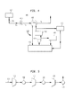
- FIG 4 illustrates another embodiment of a cooling system 400 comprising an air-cooled system 410 and a water-cooled system 460.
- the air-cooled system 410 may correspond to an air-cooled device similar to that described in Figure 1 and typically forms part of an air separation plant.
- the air-cooled system 410 may be similar to the closed loop cooling circuit 210 illustrated in Figure 2, where cooling of a hot fluid stream 404 from a heat source 402 is achieved by heat exchange with a circulating liquid coolant, which in turn is cooled by an air-cooled device.
- the hot fluid stream 404 After being cooled from an initial temperature T h to a temperature T i , the hot fluid stream 404 is further cooled to a final temperature T f by the water-cooled system 460.
- the water-cooled system 460 comprises a water-cooled device 420 coupled to a water source 422, which is a body of water such as a river, lake or sea. Water from this water source 422 is provided to the water-cooled device 420 by a water pump 424. After heat exchange with the hot fluid 404 in the water-cooled device 420, the cooling water is discharged into the water source 422.
- a chiller 426 may be used to provide additional chilling of the cooling water prior to entering the water-cooled device 420.
- cooling water from the water source 422 may be used to provide cooling to other services or equipment 440, 442, as desired.
- this once-through water cooling system may be used as part of the hybrid cooling systems previously illustrated in Figures 1-3. That is, the evaporative tower circuits previously shown in Figures 1-3 may well be replaced by or incorporate a water source that is open to the atmosphere, such as a river, lake, sea and so on.
- the water-cooled stage comprises an evaporative water tower or an open body of water for heat rejection.
- a closed-loop coolant circuit may also be provided in the water-cooled stage.
- the hot fluid stream may undergo heat exchange with a coolant in the closed-loop circuit, which then exchanges heat with an evaporative water tower or an open body of water for final heat rejection.
- Embodiments of the present invention are generally applicable to provide cooling for major equipment or machinery in an industrial plant.
- a hybrid cooling system can be used, for example, as a compressor intercooler between different compressor stages in an industrial plant, or for cooling compressor/expander systems. Under certain circumstances, the hybrid cooling system can also be applied to refrigeration unit condensers.
- Figure 5 illustrates schematically several compressor stages 510, 512 and 514 arranged in series to provide sequential compression of a gas stream 520 to increasingly higher pressures. The compression stages may form part of an air separation plant. Cooling of the compressed gas streams exiting compressor stages 510 and 512 are achieved by respective intercoolers 530 and 532 having the hybrid cooling designs of the present invention. By cooling the compressed gas streams after each stage of compression, efficient gas compression can be achieved at reduced cost. If desired, the hybrid cooling system may also be used as an aftercooler. Although there will not be a power saving for the compressor itself, capital costs of downstream equipment, e.g., sieve costs for pre-purification units, can be reduced.
- the air stream 520 may enter compressor stage 510 at a first pressure P 1 of about 1 atma and a temperature T 1 of about 21°C.
- the gas stream may have a pressure P 2 of about 2 atma and a temperature T 2 of about 100°C.
- the intercooler 530 having one of the hybrid cooling designs of the present invention is used to cool the compressed gas stream to a lower temperature, e.g., about 26°C.
- the cooled gas stream is then subjected to further compression in compressor stage 512 to about 4 atma and a temperature of about 105°C.
- This further compressed air stream can be cooled back to about 26°C by another intercooler 532 prior to entering the next compressor stage 514, after which, an aftercooler 534 may be used to cool the compressed gas stream to a desired temperature.
- the pressure and temperature conditions cited in the above examples are meant for illustrative purpose only. Depending on the compressor designs or specific applications, other pressure and temperature ranges may be obtained for the various gas streams. Furthermore, the hybrid cooling system is generally applicable to a wide range of operating pressure or temperature conditions, and are well-suited for cooling needs associated with machinery or equipment in industrial plants or for cooling process fluids from an air separation plant.
- the hybrid cooling systems provide several advantages over conventional cooling systems. For example, by operating an air-cooled device at a large approach temperature in the first cooling stage, the surface area and the fan power requirements for the air-cooled device may be reduced. This results in a lower cost per unit heat rejection compared to an air-cooled system that is designed for operation at lower approach temperatures. With the water-cooled part of the hybrid system, operation at tight approaches is achievable, which in turn, allows compressor operation to be performed at higher efficiency. Furthermore, lower final temperatures can be achieved (compared to air cooling alone) as a result of evaporative cooling effect associated with the water cooling stage. Systems with air coolers alone normally run with higher approaches, resulting in higher compression costs.
- hybrid cooling For cooling systems having evaporative cooling towers, the use of hybrid cooling as described herein allows a considerable reduction in the water make up and blowdown requirements compared to conventional systems using evaporative cooling alone, since a portion of the heat is removed by air cooling.
- the hybrid cooling approach allows a reduction in the amount of heat disposed to the body of water. The overall effect is that the hybrid cooling system will have a lower capital and operating cost than air-cooled systems designed in accordance with normal guidelines, but would achieve performance levels close to conventional evaporative systems at reduced makeup requirements and/or environmental impact on the water resource.
Landscapes
- Engineering & Computer Science (AREA)
- Physics & Mathematics (AREA)
- Mechanical Engineering (AREA)
- Thermal Sciences (AREA)
- General Engineering & Computer Science (AREA)
- Other Air-Conditioning Systems (AREA)
- Separation By Low-Temperature Treatments (AREA)
- Cultivation Of Plants (AREA)
- Greenhouses (AREA)
Abstract
Description
Claims (13)
- A cooling system for use in an air separation plant, comprising:an air-cooled stage downstream of equipment in said air separation plant, the air-cooled stage for cooling a hot fluid stream associated with said equipment to a first temperature; anda water-cooled stage for cooling said hot fluid stream further to a second temperature downstream of said air-cooled stage.
- A cooling system according to claim 1, wherein said water-cooled stage comprises a water-cooled device, a water source, and a pump for delivering a water coolant stream from said water source to said water-cooled device.
- A cooling system according to claim 1 or claim 2, wherein said air-cooled stage comprises a heat exchange section, an air cooler, and a pump for circulating a coolant stream between said heat exchange section and said air cooler; said heat exchange section being configured for heat exchange between said hot fluid stream and said coolant stream.
- A cooling system according to claim 1 or claim 2, wherein said air-cooled stage and said water-cooled stage are coupled in series to a heat exchange section and a circulating pump, said air-cooled stage being downstream from said heat exchange section to provide air cooling of said hot fluid stream to said first temperature.
- A cooling system according to claim 4, wherein said air-cooled stage is a non-evaporative air cooler and said water-cooled stage is an evaporative water tower
- A cooling system according to any one of the preceding claims, wherein said equipment is a compression stage or a series of compression stages.
- A method of cooling for use in an air separation plant, comprising:a) cooling a hot fluid stream associated with equipment in said air separation plant to a first temperature using an air-cooled stage; andb) cooling said hot fluid stream further to a second temperature in a water-cooled stage downstream from said air-cooled stage.
- A method according to claim 7, wherein said water-cooled stage comprises a water-cooled device, a water source, and a pump for delivering a water coolant stream from said water source to said water-cooled device for cooling said hot fluid stream to said second temperature.
- A method according to claim 7, wherein said air-cooled stage is selected from the group consisting of a fin fan air cooler and a liquid circulating circuit; said liquid circulating circuit comprising a heat exchange section, an air-cooled device and a pump for circulating a liquid coolant between said heat exchange section and said air-cooled device.
- A method according to any one of claims 7 to 9, wherein said hot fluid stream is a process stream exiting from said equipment or a coolant stream heated by heat exchange with said process stream.
- A method of cooling according to any one of claims 7 to 10, wherein the equipment is a compression stage or a plurality of compression stages.
- A method of cooling for use in an industrial plant comprising:a) cooling to a first temperature using an air cooled stage a hot fluid stream originating from equipment in said industrial plant, the equipment being a compressor or a compressor-expander system;b) cooling the hot fluid stream from the first temperature to a second temperature using a water cooled stage.
- A method according to claim 12, wherein said hot fluid stream is a compressed air stream from a first compressor, and said method further comprises introducing said compressed air stream at said second temperature into a second compressor.
Applications Claiming Priority (2)
| Application Number | Priority Date | Filing Date | Title |
|---|---|---|---|
| US31244101P | 2001-08-15 | 2001-08-15 | |
| US312441P | 2001-08-15 |
Publications (2)
| Publication Number | Publication Date |
|---|---|
| EP1284402A2 true EP1284402A2 (en) | 2003-02-19 |
| EP1284402A3 EP1284402A3 (en) | 2004-07-28 |
Family
ID=23211447
Family Applications (1)
| Application Number | Title | Priority Date | Filing Date |
|---|---|---|---|
| EP02255605A Withdrawn EP1284402A3 (en) | 2001-08-15 | 2002-08-09 | System and method of cooling |
Country Status (4)
| Country | Link |
|---|---|
| US (1) | US20030033831A1 (en) |
| EP (1) | EP1284402A3 (en) |
| CN (1) | CN1405523A (en) |
| MX (1) | MXPA02007811A (en) |
Cited By (6)
| Publication number | Priority date | Publication date | Assignee | Title |
|---|---|---|---|---|
| EP1705443A1 (en) * | 2005-02-11 | 2006-09-27 | Linde Aktiengesellschaft | Process and apparatus for cooling a gas by direct heat exchange with a liquid refrigerant |
| FR2918741A1 (en) * | 2007-07-12 | 2009-01-16 | Air Liquide | INTEGRATION OF SEVERAL UNITS OF SEPARATION. |
| US7536873B2 (en) | 2005-02-11 | 2009-05-26 | Linde Aktiengesellschaft | Process and device for cooling a gas by direct heat exchange with a cooling liquid |
| EP3904815A1 (en) * | 2020-04-30 | 2021-11-03 | Air Products And Chemicals, Inc. | Process for enhanced closed-circuit cooling system |
| EP3885684A3 (en) * | 2020-03-05 | 2022-03-23 | L'air Liquide, Societe Anonyme Pour L'etude Et L'exploitation Des Procedes Georges Claude | Air separation system |
| EP4567359A3 (en) * | 2023-12-06 | 2025-08-06 | L'air Liquide, Societe Anonyme Pour L'etude Et L'exploitation Des Procedes Georges Claude | Compressed gas cooling apparatus and air separation device provided with a compressed gas cooling apparatus |
Families Citing this family (6)
| Publication number | Priority date | Publication date | Assignee | Title |
|---|---|---|---|---|
| WO2011149487A2 (en) * | 2010-05-27 | 2011-12-01 | Johnson Controls Technology Company | Thermosyphon coolers for cooling systems with cooling towers |
| CN105444316B (en) * | 2016-01-18 | 2022-05-10 | 深圳市海吉源科技有限公司 | Ultra-large temperature difference single tube long-distance water cold accumulation and supply system |
| EP3309488A1 (en) * | 2016-10-13 | 2018-04-18 | Shell International Research Maatschappij B.V. | System for treating and cooling a hydrocarbon stream |
| WO2020126121A1 (en) | 2018-12-21 | 2020-06-25 | Technip France | Method for constructing and exploiting a hydrocarbons production facility, notably on an expanse of water, and associated exploitation facility |
| PL4098964T3 (en) * | 2021-05-31 | 2023-07-24 | Ovh | Cooling arrangement comprising a closed loop, a semi-open loop and at least one fan |
| CN113587287B (en) * | 2021-08-06 | 2025-09-12 | 宝加国际有限公司 | Ultra-efficient phase-change energy storage and variable-load central air-conditioning system |
Family Cites Families (3)
| Publication number | Priority date | Publication date | Assignee | Title |
|---|---|---|---|---|
| NL113348C (en) * | 1959-10-23 | 1966-11-15 | ||
| FR2710370B1 (en) * | 1993-09-21 | 1995-12-08 | Air Liquide | Method and assembly for compressing a gas. |
| FR2828273A1 (en) * | 2001-07-31 | 2003-02-07 | Air Liquide | Air distillation method uses two adsorbers to purify air in operating cycle with adsorption and regeneration phases |
-
2002
- 2002-07-29 US US10/207,500 patent/US20030033831A1/en not_active Abandoned
- 2002-08-09 EP EP02255605A patent/EP1284402A3/en not_active Withdrawn
- 2002-08-13 MX MXPA02007811A patent/MXPA02007811A/en unknown
- 2002-08-15 CN CN02130221A patent/CN1405523A/en active Pending
Cited By (7)
| Publication number | Priority date | Publication date | Assignee | Title |
|---|---|---|---|---|
| EP1705443A1 (en) * | 2005-02-11 | 2006-09-27 | Linde Aktiengesellschaft | Process and apparatus for cooling a gas by direct heat exchange with a liquid refrigerant |
| US7536873B2 (en) | 2005-02-11 | 2009-05-26 | Linde Aktiengesellschaft | Process and device for cooling a gas by direct heat exchange with a cooling liquid |
| FR2918741A1 (en) * | 2007-07-12 | 2009-01-16 | Air Liquide | INTEGRATION OF SEVERAL UNITS OF SEPARATION. |
| EP3885684A3 (en) * | 2020-03-05 | 2022-03-23 | L'air Liquide, Societe Anonyme Pour L'etude Et L'exploitation Des Procedes Georges Claude | Air separation system |
| US11959702B2 (en) | 2020-03-05 | 2024-04-16 | L'air Liquide, Societe Anonyme Pour L'etude Et L'exploitation Des Procedes Georges Claude | Air separation device |
| EP3904815A1 (en) * | 2020-04-30 | 2021-11-03 | Air Products And Chemicals, Inc. | Process for enhanced closed-circuit cooling system |
| EP4567359A3 (en) * | 2023-12-06 | 2025-08-06 | L'air Liquide, Societe Anonyme Pour L'etude Et L'exploitation Des Procedes Georges Claude | Compressed gas cooling apparatus and air separation device provided with a compressed gas cooling apparatus |
Also Published As
| Publication number | Publication date |
|---|---|
| EP1284402A3 (en) | 2004-07-28 |
| US20030033831A1 (en) | 2003-02-20 |
| CN1405523A (en) | 2003-03-26 |
| MXPA02007811A (en) | 2004-09-27 |
Similar Documents
| Publication | Publication Date | Title |
|---|---|---|
| US6895773B2 (en) | Heat pump apparatus for regulating motor vehicle temperature | |
| JP5107464B2 (en) | Equipment for supercharged combustion engines | |
| US9156333B2 (en) | System for the heating, ventilation, and/or air conditioning of a vehicle, comprising at least one heat exchanger through which a heat-transfer fluid flows | |
| CN1333214C (en) | Method and device for cooling circulating air | |
| US4457358A (en) | Heating and cooling system | |
| CN101734142B (en) | Method and system for additional cooling of coolant in a vehicle cooling system | |
| US20080302113A1 (en) | Refrigeration system having heat pump and multiple modes of operation | |
| US20090078220A1 (en) | Cooling System with Isolated Cooling Circuits | |
| CN110595013A (en) | Air conditioner refrigeration method and system for data center and data center | |
| US20030033831A1 (en) | System and method of cooling | |
| US20140338391A1 (en) | Multi-stage evaporative heat rejection process cycle that facilitates process cooling efficiency, water production, and/or water reclamation for fluid coolers and cooling towers | |
| RU2766509C2 (en) | Modular water economizer for air-cooled coolers | |
| US11800692B2 (en) | System and method for data center cooling with carbon dioxide | |
| US6330809B1 (en) | Application of a chiller in an apparatus for cooling a generator/motor | |
| CN102818326A (en) | Large temperature difference air conditioning system for heat extraction of data center and using method thereof | |
| TWI811668B (en) | A method, apparatus and system for cooling a gas stream | |
| CN100414222C (en) | Modularized refrigerating unit with flooding type vaporization system | |
| CN212644808U (en) | Air-conditioning refrigeration system for data center | |
| JP2007139262A (en) | Water-cooled heat pump air conditioner | |
| JPH06272993A (en) | Engine-driven cooler/heater | |
| CN213687342U (en) | A low-temperature screw chiller used in ice rinks | |
| CN121510516A (en) | Air conditioning systems and combined air-liquid refrigeration data centers | |
| CN121908530A (en) | Heat removal management system with cascaded heat exchange for heat generating electronic equipment | |
| CN119880476A (en) | Test device and test system | |
| CN117812870A (en) | cooling system |
Legal Events
| Date | Code | Title | Description |
|---|---|---|---|
| PUAI | Public reference made under article 153(3) epc to a published international application that has entered the european phase |
Free format text: ORIGINAL CODE: 0009012 |
|
| AK | Designated contracting states |
Designated state(s): AT BE BG CH CY CZ DE DK EE ES FI FR GB GR IE IT LI LU MC NL PT SE SK TR |
|
| AX | Request for extension of the european patent |
Extension state: AL LT LV MK RO SI |
|
| PUAL | Search report despatched |
Free format text: ORIGINAL CODE: 0009013 |
|
| AK | Designated contracting states |
Kind code of ref document: A3 Designated state(s): AT BE BG CH CY CZ DE DK EE ES FI FR GB GR IE IT LI LU MC NL PT SE SK TR |
|
| AX | Request for extension of the european patent |
Extension state: AL LT LV MK RO SI |
|
| AKX | Designation fees paid | ||
| REG | Reference to a national code |
Ref country code: DE Ref legal event code: 8566 |
|
| STAA | Information on the status of an ep patent application or granted ep patent |
Free format text: STATUS: THE APPLICATION IS DEEMED TO BE WITHDRAWN |
|
| 18D | Application deemed to be withdrawn |
Effective date: 20050129 |