EP1283498A2 - White line detection apparatus and white line detection method - Google Patents
White line detection apparatus and white line detection method Download PDFInfo
- Publication number
- EP1283498A2 EP1283498A2 EP02255334A EP02255334A EP1283498A2 EP 1283498 A2 EP1283498 A2 EP 1283498A2 EP 02255334 A EP02255334 A EP 02255334A EP 02255334 A EP02255334 A EP 02255334A EP 1283498 A2 EP1283498 A2 EP 1283498A2
- Authority
- EP
- European Patent Office
- Prior art keywords
- image
- white line
- pixel values
- maximum value
- area
- Prior art date
- Legal status (The legal status is an assumption and is not a legal conclusion. Google has not performed a legal analysis and makes no representation as to the accuracy of the status listed.)
- Granted
Links
Images


Classifications
-
- G—PHYSICS
- G06—COMPUTING OR CALCULATING; COUNTING
- G06T—IMAGE DATA PROCESSING OR GENERATION, IN GENERAL
- G06T5/00—Image enhancement or restoration
- G06T5/90—Dynamic range modification of images or parts thereof
- G06T5/94—Dynamic range modification of images or parts thereof based on local image properties, e.g. for local contrast enhancement
-
- G—PHYSICS
- G06—COMPUTING OR CALCULATING; COUNTING
- G06T—IMAGE DATA PROCESSING OR GENERATION, IN GENERAL
- G06T5/00—Image enhancement or restoration
- G06T5/40—Image enhancement or restoration using histogram techniques
-
- G—PHYSICS
- G06—COMPUTING OR CALCULATING; COUNTING
- G06T—IMAGE DATA PROCESSING OR GENERATION, IN GENERAL
- G06T7/00—Image analysis
- G06T7/10—Segmentation; Edge detection
- G06T7/11—Region-based segmentation
-
- G—PHYSICS
- G06—COMPUTING OR CALCULATING; COUNTING
- G06T—IMAGE DATA PROCESSING OR GENERATION, IN GENERAL
- G06T7/00—Image analysis
- G06T7/70—Determining position or orientation of objects or cameras
-
- G—PHYSICS
- G06—COMPUTING OR CALCULATING; COUNTING
- G06V—IMAGE OR VIDEO RECOGNITION OR UNDERSTANDING
- G06V20/00—Scenes; Scene-specific elements
- G06V20/50—Context or environment of the image
- G06V20/56—Context or environment of the image exterior to a vehicle by using sensors mounted on the vehicle
- G06V20/588—Recognition of the road, e.g. of lane markings; Recognition of the vehicle driving pattern in relation to the road
-
- G—PHYSICS
- G06—COMPUTING OR CALCULATING; COUNTING
- G06T—IMAGE DATA PROCESSING OR GENERATION, IN GENERAL
- G06T2207/00—Indexing scheme for image analysis or image enhancement
- G06T2207/10—Image acquisition modality
- G06T2207/10016—Video; Image sequence
-
- G—PHYSICS
- G06—COMPUTING OR CALCULATING; COUNTING
- G06T—IMAGE DATA PROCESSING OR GENERATION, IN GENERAL
- G06T2207/00—Indexing scheme for image analysis or image enhancement
- G06T2207/20—Special algorithmic details
- G06T2207/20004—Adaptive image processing
- G06T2207/20012—Locally adaptive
-
- G—PHYSICS
- G06—COMPUTING OR CALCULATING; COUNTING
- G06T—IMAGE DATA PROCESSING OR GENERATION, IN GENERAL
- G06T2207/00—Indexing scheme for image analysis or image enhancement
- G06T2207/30—Subject of image; Context of image processing
- G06T2207/30248—Vehicle exterior or interior
- G06T2207/30252—Vehicle exterior; Vicinity of vehicle
- G06T2207/30256—Lane; Road marking
Definitions
- the present invention relates to an apparatus and a method adopted to identify the contour of a road by detecting a white line present on the road.
- Japanese Laid-Open Patent Publication No. 2000-335340 discloses a method for raising the contrast of an image captured by an on-vehicle camera.
- a density variation histogram is prepared from the captured image and density conversion is implemented so as to modify the densities within the range between the highest and the lowest density levels obtained in a uniform manner by excluding certain density levels at the two extreme ends in the histogram at a predetermined density level.
- the publication also proposes a method of image density conversion which is achieved by emphasizing a dark area or a light area based upon the relationship between the density level at the barycenter of the histogram and the central value of the density levels. The accuracy of object detection is improved by achieving better contrast in the captured image through either of these methods.
- the uniform density conversion also results in the contrast of road surface areas other than the white line becoming emphasized.
- the S/N ratio of the white line is not improved and the white line cannot be detected with a high degree of reliability.
- the image density conversion whereby a light area of the image is emphasized in the related art emphasizes any area that is lighter than the white line on the road surface, and an erroneous detection of a white line may occur as a result.
- an erroneous detection of a nonexistent white line can readily occur.
- a white line detection apparatus comprises an extraction means for extracting an image of a white line detection processing area set within a road image captured by an image-capturing means, a maximum value estimating means for estimating a maximum value among pixel values constituting the image of the road surface over the area other than a white line based upon the pixel values representing the image extracted by the extraction means, a reduction means for reducing the contrast of an image corresponding to pixel values equal to or lower than the maximum value among the pixel values constituting the image of the road surface over the area other than the white line which has been estimated by the maximum value estimation means and a detection means for detecting the white line based upon the image whose contrast has been lowered by the reducing means.
- a white line detection method an image of a white line detection processing area set within a road image captured by an image-capturing means is extracted, a maximum value among pixel values constituting an image of road surface areas other than a white line is estimated based upon pixel values corresponding to the extracted image, the contrast of an image represented by pixel values equal to or lower than the maximum value among the pixel values constituting the image of the road surface over the area other than the white line which has been estimated is reduced and the white line is detected based upon the image whose contrast has been reduced.
- FIG. 1 shows the structure adopted in an embodiment of the white line detection apparatus according to the present invention.
- the white line detection apparatus in the embodiment comprises a camera 1, an image processing device 2, a memory 3, a sensor 4, and a display 5.
- the camera 1 which is mounted at the center along the vehicle width at the top of the front window in the cabin as shown in FIG. 2, captures an image of the road extending ahead of the vehicle.
- the camera 1 is installed by ensuring that the yaw angle formed by the optical axis of the lens of the camera 1 and the vehicle center line is set to 0 and that the pitch angle is set to a predetermined angle.
- the captured image is cyclically provided to the image processing device 2.
- the image processing device 2 detects a white line on the road by processing the image captured by the camera 1.
- the sensor 4 detects the vehicle behavior including the vehicle speed, the pitch angle, the yaw angle, and the like.
- the display 5 is a display device on which the road state such as the presence of the white line having been detected and the like is displayed.
- the image processing device 2 estimates the position of the white line in the image transmitted from the camera 1 based upon the geometrical conditions of the white line and updates a road model to be detailed later by ascertaining the degree of displacement of the current white line position relative to the white line position in the road model. As a result, it becomes possible to estimate the white line position in a stable manner on a continuous basis.
- FIG. 3 shows an image of a road captured by the camera 1. White lines are drawn at the two sides of the 2-lane road, with a broken line drawn down the center. The rectangular enclosed area is the white line detection area, which is set based upon the results of the previous white line detection. The image processing device 2 detects the white line by implementing the processing which is to be detailed later on the image of the white line detection area.
- FIG. 4 presents a flowchart of the procedure for white line detection processing executed by the image processing device in the white line detection apparatus according to the present invention.
- the processing in step S1 and subsequent steps is started up as an image captured by the camera 1 is transmitted to the image processing device 2.
- step S1 the area over which the white line detection is to be performed is set as mentioned earlier and the operation proceeds to step S2.
- the processing in step S2 and subsequent steps is implemented over the white line detection area set in step S1.
- the density gradient of low spatial frequencies which are present over, for instance, the entire processing area in the original image is corrected and flattened.
- the term "spatial frequency" is used to refer to a frequency that reflects a spatial (locale-related) distribution of the image brightness or the color difference.
- step S2 the image is smoothed in order to calculate a density gradient correction coefficient ⁇ which is to be detailed later. Any of various methods may be adopted to smooth the image.
- the image is smoothed through the moving average method achieved by ascertaining the moving average of pixel values over an area of a predetermined size.
- the moving average method the average of the values indicated by the pixels surrounding a target pixel and the value of the target pixel is used to replace the value at the target pixel. It is necessary to set the pixel area ranging over the predetermined size to a width corresponding to the width of a pixel area ranging over the white line, e.g., approximately 5 times the width of the pixel area matching the white line width.
- the size of the pixel area ranging over the white line width is determined through approximation in correspondence to the position of the white line detection area on the image based upon the manner with which the camera is mounted on the vehicle and the image-capturing direction, it should be ascertained and stored in the memory 3 in advance in correspondence to each image processing area.
- the image must be smoothed over an area that is larger than the pixel area required for the actual white line detection, since a smoothing operation requires a pixel area surrounding the actual white line area. Accordingly, the processing area size over which the original image is processed by the image processing device 2 should be set to a size which is larger by the size of the pixel area surrounding the white line area.
- step S3 the density gradient correction coefficient ⁇ to be used to flatten the density in correspondence to a density value (pixel value) at each pixel constituting the original image is calculated through the formula in expression (1).
- ⁇ (x, y) Is_avg/Is(x, y) with ⁇ (x, y): coefficient for flattening the density at coordinates (x, y);
- step S4 the density gradient of the image is flattened.
- step S5 a density histogram of the image with the flattened density gradient is prepared.
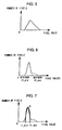
- FIG. 5 shows the density histogram prepared by using the original image before undergoing the image processing.
- the horizontal axis represents the pixel value, whereas the vertical axis represents the number of pixels (frequency).
- FIG. 6 shows the density histogram obtained after flattening the density gradient of the original image.
- the maximum pixel value is indicated as If_max and the minimum pixel value is indicated as If_min.
- the pixel value corresponding to the largest number of pixels in the density histogram in FIG. 6 can be regarded as the median of the density in the image of road surface areas other than the white line.
- step S6 the maximum value Ir_max and the minimum value Ir_min among the pixel values in the road surface area other than the white line are calculated.
- Ir_max and Ir_min are calculated by using an approximated curve (density histogram) representing the density distribution at a road surface with uniform density which is obtained in advance.
- the approximated curve is determined as shown in Fig. 7 with the index point A indicating the pixel value and number of pixels corresponding to the highest frequency in the density histogram.
- the approximated curve used in this process may be, for instance, a quadratic curve.
- the apex of the quadratic curve is matched with the index point A as shown in FIG. 7.
- the relationship between the pixel value I and the number of pixels N in the quadratic curve is as expressed below in expression (3).
- N - ⁇ (I - Ip) 2 + Np
- the maximum value Ir_max and the minimum value Ir_min among the pixel values over the areas of the road surface other than the white line can be ascertained as intersecting points of the quadratic curve mentioned above and the horizontal axis representing the pixel value.
- the maximum value Ir_max is calculated through the formula in expression (4) and the minimum value Ir_min is calculated through the formula in expression (5) below.
- Ir_max Ip + ⁇ (NP/ ⁇ )
- Ir_min Ip - ⁇ (NP/ ⁇ )
- step S7 it is judged as to whether or not a white line is present inside the white line detection area set in step S1. It is judged that no white line is present if the number of pixels present inside the approximated curve representing the density distribution of the road surface with a uniform density achieves a rate higher than a predetermined rate relative to the entire number of pixels in the histogram shown in FIG. 6. If, on the other hand, the number of pixels present inside the approximated curve represents a rate equal to or lower than the predetermined rate relative to the entire number of pixels in the histogram in FIG. 6, it is decided that a white line is present in the white line detection area. The number of pixels present on the inside of the approximated curve depends upon the value of the coefficient ⁇ in expression (3).
- ⁇ is set to 2.5 and the predetermined rate is set to 0.85 in the embodiment by assuming that the white line detection area is approximately 3 times as large as the area of the white line.
- step S7 If it is judged that a white line is present in step S7, the operation proceeds to step S8.
- step S8 a density conversion formula to be used to emphasize the white line area is calculated. If, on the other hand, it is judged in step S7 that no white line is present, the operation proceeds to step S9.
- step S9 a density conversion formula which allows the flattened image to be directly output is calculated. The following is an explanation of the method for calculating the density conversion formula adopted when it is judged that a white line is present in the white line detection area.
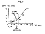
- V1 and V2 respectively represent the output values (converted density values) obtained by inputting the maximum pixel value If_max and the minimum pixel value If_min in the image whose density gradient has been flattened in step S4.
- FIG. 8 shows the relationship between an input pixel value and the corresponding output pixel value.
- V1 represents the pixel value with the largest output whereas V2 represents the pixel value with the smallest output.
- the values V1 and V2 are determined in conformance to the requirements imposed in the white line detection processing.
- the maximum output value V1 and the minimum output value V2 are respectively 2 n -1 and 0 with n (bits) representing the value of a given pixel.
- a point P1 indicates the output pixel value V1 obtained by inputting the maximum pixel value If_max and a point P2 indicates the output pixel value V2 obtained by inputting the minimum value Ir_min among the pixel values over the areas of the road surface other than the white line.
- the output pixel value obtained by inputting Ir_min is equal to the output pixel value obtained by inputting the minimum pixel value If_min.
- an arbitrary point P3 representing the output value obtained by inputting the maximum value Ir_max among the pixel values over the areas of the road surface other than the white line, having been calculated in step S5, is set.
- V3 indicates the output pixel value corresponding to the point P3.
- the extent of the inclination of the straight line 1 ⁇ is larger than the extent of the inclination of the straight line connecting the point P1 and the point P2.
- the output value is calculated by using the straight line 2 ⁇ or the curve 2 ⁇ ' connecting the point P2 and the point P3.
- the inclination of the straight line 2 ⁇ or the curve 2 ⁇ ' connecting the point P2 and the point P3 should be set equal to or smaller than the extent of the inclination of the straight line 1 ⁇ connecting the point P1 and the point P3.
- the output value V3 at the point P3 can be set to any value as long as it is smaller than V4 in FIG. 8.
- the density values over the areas of the road surface other than the white line are merely estimated values, there is the possibility that some pixel values representing the white line are present among the pixel values equal to or smaller than the maximum pixel value Ir_max over the areas of the road surface other than the white line. Since it becomes more difficult to detect the white line if the inclination of the straight line 2 ⁇ is reduced to an excessive degree in such a case, the value of V3 must be set by ensuring that the inclination of the straight line 2 ⁇ is not reduced too much.
- the value of V3 may be, for instance, (V4)/2.
- the inclination of the curve 2 ⁇ ' should be set closer to the inclination of the straight line 1 ⁇ in the vicinity of the point P3 with the inclination reduced closer to the point P2, since the likelihood of the curve containing pixel values constituting the white line becomes higher in the vicinity of the point P3 and becomes lower as the curve 2 ⁇ ' nears the point P2.
- the curve 2 ⁇ ' which assumes a shape with the apex oriented downward, is expressed as the following expression (8).
- V3 ⁇ V1 ⁇ (Ir_max - Ir_min) + 2 ⁇ (If_max - Ir_max) ⁇ V2 ⁇ / ⁇ 2 ⁇ (If_max - Ir_max) + (Ir_max - Ir_min) ⁇
- the density conversion formulae used when it is judged that a white line is present are summarized below. If the input pixel value is between Ir_max and If_max, the density conversion is implemented by using expression (6) (straight line 1 ⁇ ). If the input pixel value is between Ir_min and Ir_max, the density conversion is executed by using either expression (7) (straight line 2 ⁇ ) or expression (8) (curve 2 ⁇ '). If the input pixel value is between If_min and Ir_min, the output pixel value is equal to the minimum pixel value V2 (straight line 3 ⁇ ). As FIG.
- the white line in the image having undergone the density conversion can be emphasized by reducing the output values corresponding to the input pixel values over the areas of the road surface other than the white line that are equal to or smaller than Ir_max and thus heightening the contrast of the white line over which the input pixel values are large.
- step S10 density conversion processing is performed on the image over the white line detection area by using the density conversion formula calculated in step S8 or S9.
- step S11 the white line is detected based upon the image having undergone the density conversion processing before the control ends. Since the present invention is characterized by the processing implemented to emphasize the contrast of the white line in the image captured by the camera 1, a detailed explanation of the white line detection processing executed in step S11 is omitted.
- the white line detection apparatus In the processing executed by the white line detection apparatus according to the present invention, after the white line detection area is set in the image captured by the camera 1 and the image is smoothed (steps S1 and S2), the density gradient of the image is flattened (steps S3 and S4). Then, the density histogram is prepared by using the image with the flattened density gradient (step S5) and the maximum value Ir_max and the minimum value Ir_min among the pixel values over the areas of the road surface other than the white line are calculated (step S6) so as to enable estimation of the road surface density over areas other than the white line.
- step S7 it is judged as to whether or not a white line is present (step S7), and if it is judged that no white line is present, a conversion formula which will provide an output value equal to the input value is calculated (step S9). If, on the other hand, it is judged that a white line is present, a density conversion formula for emphasizing the white line in the image of the road surface is calculated and the density conversion is executed by using the formula before detecting the white line (steps S8, S10 and S11).
- the white line detection apparatus which executes the density conversion after flattening the density gradient of the image, the reliability with which the areas of the road surface other than the white line are identified is improved and thus the white line can be detected with a high degree of reliability even when there is inconsistency in the road surface density. Since the output values over the identified road surface areas other than the white line are reduced and the output values over the areas where the white line is likely to be present are increased through the density conversion, the S/N ratio in the white line area is improved so as to enable reliable detection even when the white line has become faded.
- the white line can be reliably detected.
- the robustness of the white line detection processing can be increased since the detection processing is not readily affected by the density over the areas of the road surface other than the white line.
- the density correction coefficient is calculated based upon the individual pixel values and the average of all the pixel values of the image obtained by smoothing the image undergoing the white line detection processing and the density gradient is corrected by using the density correction coefficient thus calculated, the density gradient is corrected over a large range within the image processing area to improve the accuracy with which the road surface areas other than the white line are identified. Thus, the accuracy with which the white line is detected, too, is improved. Furthermore, since the density conversion processing is executed only when it is judged that a white line is present, erroneous detection of a nonexistent white line does not occur, which is attributable to an emphasized contrast of the road surface which may result from the density conversion executed when there is no white line.
- the above described embodiment is an example, and various modifications can be made without departing from the spirit and scope of the invention.
- the present invention is characterized in that the maximum value among the pixel values constituting the image of the road surface area other than the white line is estimated based upon the pixel values constituting the image of the white line detection processing area set within a captured road image and in that a white line is detected based upon the image having undergone the image processing through which the contrast of the image constituted of pixels with values equal to or smaller than the maximum value is lowered. Accordingly, the present invention is not restricted by the particulars of the method explained in reference to the embodiment and may be adopted in any image processing method through which the processing characterizing the present invention as described above is implemented.
Landscapes
- Engineering & Computer Science (AREA)
- Physics & Mathematics (AREA)
- General Physics & Mathematics (AREA)
- Theoretical Computer Science (AREA)
- Computer Vision & Pattern Recognition (AREA)
- Multimedia (AREA)
- Image Analysis (AREA)
- Image Processing (AREA)
- Traffic Control Systems (AREA)
Abstract
Description
I (x, y) : the pixel value at coordinates (x, y) in the original image.
Claims (7)
- A white line detection apparatus comprising:extraction means (2) for extracting an image of a white line detection processing area set within a road image captured by image-capturing means (1);maximum value estimation means (2) for estimating a maximum value among pixel values constituting an image of a road surface over the area other than a white line based upon the pixel values corresponding to the image extracted by the extraction means (2);contrast reduction means (2) for reducing the contrast of an image corresponding to pixel values equal to or smaller than the maximum value among pixel values constituting the image of the road surface over the area other than the white line which has been estimated by the maximum value estimation means (2); anddetection means (2) for detecting the white line based upon the image whose contrast has been lowered by the contrast reduction means (2).
- A white line detection apparatus according to claim 1, further comprising:wherein:density gradient correction means (2) for correcting a density gradient of the image over the white line detection processing area extracted by the extraction means (2),the maximum value estimation means (2) estimates the maximum value among the pixel values constituting the image of the road surface over the area other than the white line based upon pixel values of an image with the density gradient thereof having been corrected by the density gradient correction means (2).
- A white line detection apparatus according to claim 1, further comprising:wherein:white line estimation means (2) for estimating whether or not a white line is present in the white line detection processing area extracted by the extraction means (2),the contrast reduction means (2) for reducing the contrast of an image area having pixel values equal to or smaller than the maximum value among the pixel values constituting the image of the road surface over the area other than the white line if the white line estimation means (2) estimates that a white line is present in the white line detection processing area.
- A white line detection apparatus according to claim 2, further comprising:image smooth means (2) for smoothing the image of the white line detection processing area, wherein:the density gradient correction means (2) corrects the density gradient by calculating a density correction coefficient based upon individual pixel values and the average of all the pixel values constituting the image having been smoothed by the image smooth means (2) and by using the density correction coefficient thus calculated.
- A white line detection apparatus according to claim 2, wherein:the maximum value estimation means (2) estimates the maximum value among the pixel values constituting the image of the road surface over the area other than the white line based upon a density histogram obtained by using the image with the density gradient thereof having been corrected by the density gradient correction means (2) and a density histogram of an image of a road surface with a uniform density.
- A white line detection apparatus according to claim 2, wherein:the maximum value estimation means (2) also estimates a minimum value among the pixel values constituting the image of the road surface over the area other than the white line; andwith P1 indicating a point at which a maximum output pixel value is obtained in correspondence to a maximum value among the pixel values constituting the image with the density gradient thereof having been corrected input as an input pixel value, P2 representing a point at which a minimum output pixel value is obtained in correspondence to the minimum value among the pixel values constituting the image of the road surface over the area other than the white line estimated by the maximum value estimation means (2) input as the input pixel value, and P3 representing a point at which an output pixel value is obtained in correspondence to the maximum value among the pixel values constituting the image of the road surface over the area other than the white line input as the input pixel value in a density conversion graph with a horizontal axis and a vertical axis thereof respectively representing the input pixel value and the output pixel value, the contrast reduction means (2) executes density conversion for pixel values between the maximum value among the pixel values constituting the image of the road surface over the area other than the white line and the maximum value among the pixel values constituting the image with the density gradient thereof having been corrected by using a conversion formula representing a straight line connecting the point P1 and the point P3 and having a larger degree of inclination than a straight line connecting the point P1 and the point P2 and executes density conversion for pixel values between the maximum value and the minimum value among the pixel values constituting the image of the road surface over the area other than the white line by using a conversion formula representing a straight line connecting the point P2 and the point P3 or a conversion formula representing a quadratic curve connecting the point P2 and the point P3 with a downward apex.
- A white line detection method comprising:extracting an image of a white line detection processing area set within a road image captured by an image-capturing means;estimating a maximum value among pixel values constituting an image of a road surface over the area other than a white line based upon pixel values corresponding to the extracted image;reducing the contrast of an image corresponding to pixel values equal to or lower than the maximum value among pixel values constituting the image of the road surface over the area other than the white line which has been estimated; anddetecting the white line based upon the image whose contrast has been reduced.
Applications Claiming Priority (2)
| Application Number | Priority Date | Filing Date | Title |
|---|---|---|---|
| JP2001237667 | 2001-08-06 | ||
| JP2001237667A JP2003051017A (en) | 2001-08-06 | 2001-08-06 | White line detector |
Publications (3)
| Publication Number | Publication Date |
|---|---|
| EP1283498A2 true EP1283498A2 (en) | 2003-02-12 |
| EP1283498A3 EP1283498A3 (en) | 2003-07-09 |
| EP1283498B1 EP1283498B1 (en) | 2007-01-17 |
Family
ID=19068707
Family Applications (1)
| Application Number | Title | Priority Date | Filing Date |
|---|---|---|---|
| EP02255334A Expired - Lifetime EP1283498B1 (en) | 2001-08-06 | 2002-07-30 | White line detection apparatus and white line detection method |
Country Status (4)
| Country | Link |
|---|---|
| US (1) | US6925206B2 (en) |
| EP (1) | EP1283498B1 (en) |
| JP (1) | JP2003051017A (en) |
| DE (1) | DE60217589T2 (en) |
Cited By (1)
| Publication number | Priority date | Publication date | Assignee | Title |
|---|---|---|---|---|
| CN102541063A (en) * | 2012-03-26 | 2012-07-04 | 重庆邮电大学 | Line tracking control method and line tracking control device for micro intelligent automobiles |
Families Citing this family (23)
| Publication number | Priority date | Publication date | Assignee | Title |
|---|---|---|---|---|
| JP3625460B2 (en) | 2002-09-27 | 2005-03-02 | 三菱電機株式会社 | On-vehicle travel lane recognition device |
| US7920725B2 (en) * | 2003-09-09 | 2011-04-05 | Fujifilm Corporation | Apparatus, method, and program for discriminating subjects |
| JP4259357B2 (en) * | 2004-03-12 | 2009-04-30 | 三菱ふそうトラック・バス株式会社 | Vehicle running state determination device |
| JP4296973B2 (en) * | 2004-03-19 | 2009-07-15 | 三菱ふそうトラック・バス株式会社 | Vehicle running state determination device |
| JP4258413B2 (en) * | 2004-03-26 | 2009-04-30 | 三菱ふそうトラック・バス株式会社 | Vehicle running state determination device |
| JP4225229B2 (en) * | 2004-03-30 | 2009-02-18 | 三菱ふそうトラック・バス株式会社 | Arousal level judgment device |
| JP4637618B2 (en) * | 2005-03-18 | 2011-02-23 | 株式会社ホンダエレシス | Lane recognition device |
| DE102005044979A1 (en) * | 2005-09-20 | 2007-03-22 | Adc Automotive Distance Control Systems Gmbh | Method for detecting lane markings |
| DE102005046672A1 (en) * | 2005-09-29 | 2007-04-05 | Robert Bosch Gmbh | Night vision device for motor vehicle, has navigating device, steering angle sensor, rotating rate sensor and radar sensor that are utilized such that roadway on which vehicle is to be driven is determined and is shown in display unit |
| JP4575275B2 (en) * | 2005-11-02 | 2010-11-04 | 三菱ふそうトラック・バス株式会社 | Vehicle display device |
| US8275170B2 (en) * | 2006-12-08 | 2012-09-25 | Electronics And Telecommunications Research Institute | Apparatus and method for detecting horizon in sea image |
| KR100886611B1 (en) * | 2007-08-14 | 2009-03-05 | 한국전자통신연구원 | Method and apparatus for extracting line segment by progressive pixel expansion in image |
| JP5034087B2 (en) * | 2008-03-31 | 2012-09-26 | 本田技研工業株式会社 | Vehicle travel support device, vehicle, vehicle travel support program |
| CN102109753A (en) * | 2009-12-25 | 2011-06-29 | 鸿富锦精密工业(深圳)有限公司 | Automatic lens detecting method |
| JP5220787B2 (en) | 2010-03-08 | 2013-06-26 | 株式会社日本自動車部品総合研究所 | In-vehicle white line recognition device |
| CN101916373B (en) * | 2010-08-11 | 2012-07-04 | 西安电子科技大学 | Road semiautomatic extraction method based on wavelet detection and ridge line tracking |
| JP5878090B2 (en) * | 2012-07-12 | 2016-03-08 | 本田技研工業株式会社 | Traveling line detector |
| JP6328369B2 (en) * | 2012-11-27 | 2018-05-23 | クラリオン株式会社 | In-vehicle control device |
| DE102014210411A1 (en) * | 2013-09-06 | 2015-03-12 | Robert Bosch Gmbh | Method and control and detection device for plausibility of a wrong-way drive of a motor vehicle |
| CN104898657A (en) * | 2014-03-06 | 2015-09-09 | 西北农林科技大学 | Robot visual sense path identification method based on DSP |
| CN103996031A (en) * | 2014-05-23 | 2014-08-20 | 奇瑞汽车股份有限公司 | Self adaptive threshold segmentation lane line detection system and method |
| CN110135302B (en) * | 2019-04-30 | 2021-08-31 | 百度在线网络技术(北京)有限公司 | Method, device, device and storage medium for training lane line recognition model |
| US12526517B2 (en) * | 2022-07-28 | 2026-01-13 | Ricoh Company, Ltd. | Method for capturing image, method for processing image, image capturing system, and information processing system |
Family Cites Families (6)
| Publication number | Priority date | Publication date | Assignee | Title |
|---|---|---|---|---|
| JPS61168078A (en) * | 1985-01-15 | 1986-07-29 | インタ−ナショナル ビジネス マシ−ンズ コ−ポレ−ション | Image processing |
| US5339368A (en) * | 1991-11-21 | 1994-08-16 | Unisys Corporation | Document image compression system and method |
| JP3083918B2 (en) * | 1992-06-26 | 2000-09-04 | 本田技研工業株式会社 | Image processing device |
| EP0827127B1 (en) * | 1996-08-28 | 2006-10-04 | Matsushita Electric Industrial Co., Ltd. | Local positioning apparatus, and method therefor |
| JP3608033B2 (en) | 1999-05-24 | 2005-01-05 | 株式会社豊田自動織機 | Vehicle reverse support device |
| JP2001101415A (en) * | 1999-09-29 | 2001-04-13 | Fujitsu Ten Ltd | Image recognizing device and image processor |
-
2001
- 2001-08-06 JP JP2001237667A patent/JP2003051017A/en active Pending
-
2002
- 2002-07-30 DE DE60217589T patent/DE60217589T2/en not_active Expired - Fee Related
- 2002-07-30 EP EP02255334A patent/EP1283498B1/en not_active Expired - Lifetime
- 2002-08-01 US US10/208,836 patent/US6925206B2/en not_active Expired - Fee Related
Cited By (2)
| Publication number | Priority date | Publication date | Assignee | Title |
|---|---|---|---|---|
| CN102541063A (en) * | 2012-03-26 | 2012-07-04 | 重庆邮电大学 | Line tracking control method and line tracking control device for micro intelligent automobiles |
| CN102541063B (en) * | 2012-03-26 | 2014-04-09 | 重庆邮电大学 | Line tracking control method and line tracking control device for micro intelligent automobiles |
Also Published As
| Publication number | Publication date |
|---|---|
| JP2003051017A (en) | 2003-02-21 |
| US20030026456A1 (en) | 2003-02-06 |
| DE60217589T2 (en) | 2007-10-25 |
| US6925206B2 (en) | 2005-08-02 |
| DE60217589D1 (en) | 2007-03-08 |
| EP1283498B1 (en) | 2007-01-17 |
| EP1283498A3 (en) | 2003-07-09 |
Similar Documents
| Publication | Publication Date | Title |
|---|---|---|
| US6925206B2 (en) | White line detection apparatus and white line detection method | |
| JP3587506B2 (en) | Stereo camera adjustment device | |
| JP3780922B2 (en) | Road white line recognition device | |
| JP5016073B2 (en) | White line recognition device | |
| US6658150B2 (en) | Image recognition system | |
| CN107370958B (en) | Image blurring processing method and device and shooting terminal | |
| US7209832B2 (en) | Lane recognition image processing apparatus | |
| US9818301B2 (en) | Lane correction system, lane correction apparatus and method of correcting lane | |
| JP4004634B2 (en) | Face image eye position detection apparatus and method | |
| US20040190787A1 (en) | Image noise reduction | |
| US8154591B2 (en) | Eyelid opening level determination device and computer readable medium storing computer program thereof | |
| JP2001160137A (en) | Monitoring system distance correction device, and monitoring system vanishing point correction device | |
| CN108280450A (en) | A kind of express highway pavement detection method based on lane line | |
| US10609303B2 (en) | Method and apparatus for rapid improvement of smog/low-light-level image using mapping table | |
| CN114757833B (en) | Vehicle side image splicing method and system | |
| CN106991407A (en) | The method and device of a kind of lane detection | |
| CN116524877A (en) | Vehicle-mounted screen brightness adjustment method and device, electronic equipment and storage medium | |
| EP2256691B1 (en) | Image processing device for vehicle and image processing program | |
| CN101029823B (en) | Method for tracking vehicle based on state and classification | |
| CN116503481B (en) | Automatic parking position and orientation detecting system based on image visual guidance | |
| US12208738B2 (en) | Method for displaying a virtual view of the area surrounding a vehicle, computer program, control unit, and vehicle | |
| JP5035139B2 (en) | Eye image processing device | |
| US11568547B2 (en) | Deposit detection device and deposit detection method | |
| CN115631119A (en) | An Image Fusion Method for Improving Target Saliency | |
| JP3977505B2 (en) | Road shape recognition device |
Legal Events
| Date | Code | Title | Description |
|---|---|---|---|
| PUAI | Public reference made under article 153(3) epc to a published international application that has entered the european phase |
Free format text: ORIGINAL CODE: 0009012 |
|
| 17P | Request for examination filed |
Effective date: 20020807 |
|
| AK | Designated contracting states |
Designated state(s): AT BE BG CH CY CZ DE DK EE ES FI FR GB GR IE IT LI LU MC NL PT SE SK TR |
|
| AX | Request for extension of the european patent |
Extension state: AL LT LV MK RO SI |
|
| PUAL | Search report despatched |
Free format text: ORIGINAL CODE: 0009013 |
|
| AK | Designated contracting states |
Designated state(s): AT BE BG CH CY CZ DE DK EE ES FI FR GB GR IE IT LI LU MC NL PT SE SK TR |
|
| AX | Request for extension of the european patent |
Extension state: AL LT LV MK RO SI |
|
| RIC1 | Information provided on ipc code assigned before grant |
Ipc: 7G 05D 1/03 B Ipc: 7G 06T 5/40 A |
|
| AKX | Designation fees paid |
Designated state(s): DE FR GB |
|
| 17Q | First examination report despatched |
Effective date: 20040309 |
|
| GRAP | Despatch of communication of intention to grant a patent |
Free format text: ORIGINAL CODE: EPIDOSNIGR1 |
|
| GRAS | Grant fee paid |
Free format text: ORIGINAL CODE: EPIDOSNIGR3 |
|
| GRAA | (expected) grant |
Free format text: ORIGINAL CODE: 0009210 |
|
| AK | Designated contracting states |
Kind code of ref document: B1 Designated state(s): DE FR GB |
|
| REG | Reference to a national code |
Ref country code: GB Ref legal event code: FG4D |
|
| REF | Corresponds to: |
Ref document number: 60217589 Country of ref document: DE Date of ref document: 20070308 Kind code of ref document: P |
|
| PGFP | Annual fee paid to national office [announced via postgrant information from national office to epo] |
Ref country code: DE Payment date: 20070726 Year of fee payment: 6 |
|
| ET | Fr: translation filed | ||
| PLBE | No opposition filed within time limit |
Free format text: ORIGINAL CODE: 0009261 |
|
| STAA | Information on the status of an ep patent application or granted ep patent |
Free format text: STATUS: NO OPPOSITION FILED WITHIN TIME LIMIT |
|
| 26N | No opposition filed |
Effective date: 20071018 |
|
| PGFP | Annual fee paid to national office [announced via postgrant information from national office to epo] |
Ref country code: GB Payment date: 20070725 Year of fee payment: 6 |
|
| PGFP | Annual fee paid to national office [announced via postgrant information from national office to epo] |
Ref country code: FR Payment date: 20070710 Year of fee payment: 6 |
|
| GBPC | Gb: european patent ceased through non-payment of renewal fee |
Effective date: 20080730 |
|
| PG25 | Lapsed in a contracting state [announced via postgrant information from national office to epo] |
Ref country code: DE Free format text: LAPSE BECAUSE OF NON-PAYMENT OF DUE FEES Effective date: 20090203 |
|
| REG | Reference to a national code |
Ref country code: FR Ref legal event code: ST Effective date: 20090331 |
|
| PG25 | Lapsed in a contracting state [announced via postgrant information from national office to epo] |
Ref country code: GB Free format text: LAPSE BECAUSE OF NON-PAYMENT OF DUE FEES Effective date: 20080730 |
|
| PG25 | Lapsed in a contracting state [announced via postgrant information from national office to epo] |
Ref country code: FR Free format text: LAPSE BECAUSE OF NON-PAYMENT OF DUE FEES Effective date: 20080731 |