EP1283421A2 - Vehicle-use bearing device having rotation detecting device - Google Patents
Vehicle-use bearing device having rotation detecting device Download PDFInfo
- Publication number
- EP1283421A2 EP1283421A2 EP02017530A EP02017530A EP1283421A2 EP 1283421 A2 EP1283421 A2 EP 1283421A2 EP 02017530 A EP02017530 A EP 02017530A EP 02017530 A EP02017530 A EP 02017530A EP 1283421 A2 EP1283421 A2 EP 1283421A2
- Authority
- EP
- European Patent Office
- Prior art keywords
- ring member
- cylindrical portion
- vehicle
- inner ring
- magnetic sensor
- Prior art date
- Legal status (The legal status is an assumption and is not a legal conclusion. Google has not performed a legal analysis and makes no representation as to the accuracy of the status listed.)
- Ceased
Links
- 230000002093 peripheral effect Effects 0.000 claims description 28
- 238000005096 rolling process Methods 0.000 claims description 20
- 238000001514 detection method Methods 0.000 claims description 6
- 239000011347 resin Substances 0.000 claims description 6
- 229920005989 resin Polymers 0.000 claims description 6
- 239000002184 metal Substances 0.000 description 3
- 230000005389 magnetism Effects 0.000 description 2
- 230000004048 modification Effects 0.000 description 2
- 238000012986 modification Methods 0.000 description 2
- 230000003139 buffering effect Effects 0.000 description 1
Images



Classifications
-
- F—MECHANICAL ENGINEERING; LIGHTING; HEATING; WEAPONS; BLASTING
- F16—ENGINEERING ELEMENTS AND UNITS; GENERAL MEASURES FOR PRODUCING AND MAINTAINING EFFECTIVE FUNCTIONING OF MACHINES OR INSTALLATIONS; THERMAL INSULATION IN GENERAL
- F16C—SHAFTS; FLEXIBLE SHAFTS; ELEMENTS OR CRANKSHAFT MECHANISMS; ROTARY BODIES OTHER THAN GEARING ELEMENTS; BEARINGS
- F16C41/00—Other accessories, e.g. devices integrated in the bearing not relating to the bearing function as such
- F16C41/007—Encoders, e.g. parts with a plurality of alternating magnetic poles
-
- G—PHYSICS
- G01—MEASURING; TESTING
- G01P—MEASURING LINEAR OR ANGULAR SPEED, ACCELERATION, DECELERATION, OR SHOCK; INDICATING PRESENCE, ABSENCE, OR DIRECTION, OF MOVEMENT
- G01P3/00—Measuring linear or angular speed; Measuring differences of linear or angular speeds
- G01P3/42—Devices characterised by the use of electric or magnetic means
- G01P3/44—Devices characterised by the use of electric or magnetic means for measuring angular speed
- G01P3/443—Devices characterised by the use of electric or magnetic means for measuring angular speed mounted in bearings
-
- G—PHYSICS
- G01—MEASURING; TESTING
- G01P—MEASURING LINEAR OR ANGULAR SPEED, ACCELERATION, DECELERATION, OR SHOCK; INDICATING PRESENCE, ABSENCE, OR DIRECTION, OF MOVEMENT
- G01P3/00—Measuring linear or angular speed; Measuring differences of linear or angular speeds
- G01P3/42—Devices characterised by the use of electric or magnetic means
- G01P3/44—Devices characterised by the use of electric or magnetic means for measuring angular speed
- G01P3/48—Devices characterised by the use of electric or magnetic means for measuring angular speed by measuring frequency of generated current or voltage
- G01P3/481—Devices characterised by the use of electric or magnetic means for measuring angular speed by measuring frequency of generated current or voltage of pulse signals
- G01P3/487—Devices characterised by the use of electric or magnetic means for measuring angular speed by measuring frequency of generated current or voltage of pulse signals delivered by rotating magnets
-
- F—MECHANICAL ENGINEERING; LIGHTING; HEATING; WEAPONS; BLASTING
- F16—ENGINEERING ELEMENTS AND UNITS; GENERAL MEASURES FOR PRODUCING AND MAINTAINING EFFECTIVE FUNCTIONING OF MACHINES OR INSTALLATIONS; THERMAL INSULATION IN GENERAL
- F16C—SHAFTS; FLEXIBLE SHAFTS; ELEMENTS OR CRANKSHAFT MECHANISMS; ROTARY BODIES OTHER THAN GEARING ELEMENTS; BEARINGS
- F16C19/00—Bearings with rolling contact, for exclusively rotary movement
- F16C19/02—Bearings with rolling contact, for exclusively rotary movement with bearing balls essentially of the same size in one or more circular rows
- F16C19/14—Bearings with rolling contact, for exclusively rotary movement with bearing balls essentially of the same size in one or more circular rows for both radial and axial load
- F16C19/18—Bearings with rolling contact, for exclusively rotary movement with bearing balls essentially of the same size in one or more circular rows for both radial and axial load with two or more rows of balls
- F16C19/181—Bearings with rolling contact, for exclusively rotary movement with bearing balls essentially of the same size in one or more circular rows for both radial and axial load with two or more rows of balls with angular contact
- F16C19/183—Bearings with rolling contact, for exclusively rotary movement with bearing balls essentially of the same size in one or more circular rows for both radial and axial load with two or more rows of balls with angular contact with two rows at opposite angles
- F16C19/184—Bearings with rolling contact, for exclusively rotary movement with bearing balls essentially of the same size in one or more circular rows for both radial and axial load with two or more rows of balls with angular contact with two rows at opposite angles in O-arrangement
- F16C19/186—Bearings with rolling contact, for exclusively rotary movement with bearing balls essentially of the same size in one or more circular rows for both radial and axial load with two or more rows of balls with angular contact with two rows at opposite angles in O-arrangement with three raceways provided integrally on parts other than race rings, e.g. third generation hubs
-
- F—MECHANICAL ENGINEERING; LIGHTING; HEATING; WEAPONS; BLASTING
- F16—ENGINEERING ELEMENTS AND UNITS; GENERAL MEASURES FOR PRODUCING AND MAINTAINING EFFECTIVE FUNCTIONING OF MACHINES OR INSTALLATIONS; THERMAL INSULATION IN GENERAL
- F16C—SHAFTS; FLEXIBLE SHAFTS; ELEMENTS OR CRANKSHAFT MECHANISMS; ROTARY BODIES OTHER THAN GEARING ELEMENTS; BEARINGS
- F16C2326/00—Articles relating to transporting
- F16C2326/01—Parts of vehicles in general
- F16C2326/02—Wheel hubs or castors
-
- F—MECHANICAL ENGINEERING; LIGHTING; HEATING; WEAPONS; BLASTING
- F16—ENGINEERING ELEMENTS AND UNITS; GENERAL MEASURES FOR PRODUCING AND MAINTAINING EFFECTIVE FUNCTIONING OF MACHINES OR INSTALLATIONS; THERMAL INSULATION IN GENERAL
- F16C—SHAFTS; FLEXIBLE SHAFTS; ELEMENTS OR CRANKSHAFT MECHANISMS; ROTARY BODIES OTHER THAN GEARING ELEMENTS; BEARINGS
- F16C33/00—Parts of bearings; Special methods for making bearings or parts thereof
- F16C33/72—Sealings
- F16C33/76—Sealings of ball or roller bearings
- F16C33/78—Sealings of ball or roller bearings with a diaphragm, disc, or ring, with or without resilient members
- F16C33/7886—Sealings of ball or roller bearings with a diaphragm, disc, or ring, with or without resilient members mounted outside the gap between the inner and outer races, e.g. sealing rings mounted to an end face or outer surface of a race
Definitions
- the present invention relates to a bearing device suitable for use in supporting a wheel on the vehicle body.
- Such a bearing device has a rolling bearing with a double raceway and a hub wheel.
- a drive shaft as a rotation shaft for a driving wheel includes a small diameter shaft portion and a large diameter shaft portion.
- the small diameter shaft portion of the drive shaft is fitted into a central hole of the hub wheel for rotation as a unit therewith while the large diameter shaft portion protrudes from the central hole of the hub wheel to a vehicle inner side.
- the rolling bearing has an inner ring which is fitted on an outer peripheral surface of the vehicle inner side of the hub wheel.
- the large diameter shaft portion and the inner ring are adjacent to each other in an axial direction, and their heights in a radial direction are approximately the same.
- Such a bearing device is provided with, as a rotation detection device, a pulser ring which rotates with the inner ring as a unit to generate rotation magnetic information and a magnetic sensor having a detection element for detecting the magnetic information from the pulser ring.
- the pulser ring is arranged on the outer peripheral surface of the vehicle inner side in a narrow annular space between the inner ring and the outer ring of the rolling bearing, which results in a low radial arrangement height from the outer diameter surface of the inner ring.
- the magnetic sensor when the magnetic sensor is positioned on an outer diameter surface of the large diameter shaft portion of the drive shaft to face the pulser ring in the axial direction, the radial arrangement height thereof becomes low corresponding to the low radial arrangement height of the pulser ring.
- a main object of the present invention is to provide a bearing device wherein a magnetic sensor having a structure of a detecting element being covered with a molded resin can be arranged with a pulser ring in an axial direction with no interference with a rotation shaft.
- the present invention may be summarized as follows.
- a bearing device comprises an outer ring member, an inner ring member concentric with the outer ring member and a pulser ring generating an electrical signal in response to a rotation of the inner ring member.
- the inner ring member has a first cylindrical portion having an outer peripheral surface on which the pulser ring is fixed and a second cylindrical portion located in a vehicle inner side of the first cylindrical portion and having a smaller outer diameter than that of the first cylindrical portion so as to form a circumferential groove together with the first cylindrical portion for accommodating a radial inner end portion of a magnetic sensor.
- the detecting element of the magnetic sensor can face the pulser ring in the axial direction.
- the structure of the present invention is different from a conventional one in which a magnetic sensor is arranged on a shoulder part of a stepped portion of a rotation shaft. Therefore a large diameter portion of the rotation shaft does not interfere with the magnetic sensor.
- the radial inner end side of the magnetic sensor can be accommodated in the circumferential groove, the radial dimension of the bearing device can be reduced to contribute to a downsizing.
- the magnetic sensor includes a detecting element and a covering member which covers the periphery of the detecting element.
- a radial inner end side of the covering member is accommodated in the circumferential groove constituted by both the first cylindrical portion and the second cylindrical portion so that the detecting element faces the pulser ring in an axial direction.
- the covering member is a molded resin.
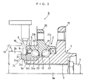
- a vehicle-use bearing device A comprises a hub wheel 1 having an axial hollow hole T and a rolling bearing with a double raceway 2 mounted on an outer peripheral surface of the hub wheel 1.
- the hub wheel 1 has a radially-outward flange 11 facing an outer peripheral surface of a vehicle outer side thereof.
- a spline is formed in a required region on an inner peripheral surface of the hollow hole T.
- a raceway groove 12 for vehicle outer side balls (rolling elements) 22 of the rolling bearing 2 is formed on an outer peripheral surface of the hub wheel 1 in a vehicle inner side with respect the flange 11.
- the rolling bearing 2 is an angular type rolling ball bearing with a double raceway and is provided with a single outer ring 21 on the inner peripheral surface as an outer ring member having raceway grooves 21a, 21b of double rows in the axial direction, a plurality of balls 22 arranged on the vehicle outer side and the vehicle inner side in double rows in the axial direction, two crown-shaped retainers 23 in the axial direction.
- the rolling bearing 2 is also composed of an inner ring 24 having a raceway groove 24a on which the vehicle inner side balls 22 roll.
- the inner ring 24 constitutes one inner ring member while the hub wheel 1 constitutes the other inner ring member.
- a drive shaft 3 as a rotation shaft is spline-fitted into the hollow hole T of the hub wheel 1.
- the vehicle outer side end portion of the drive shaft 3 is fastened by a nut 4 so that the drive shaft 3 is fixed on the hub wheel 1.
- the inner ring 24 has a first cylindrical portion 24b which faces the vehicle inner side end portion of the outer ring 21 in the radial direction in the vehicle inner side with respect to the raceway groove 24a.
- the inner ring 24 also has, in the vehicle inner side of the first cylindrical portion 24b, a second cylindrical portion 24c which projects toward the vehicle inner side direction with respect to the vehicle inner side end portion of the outer ring 21 and which has a smaller outer diameter than that of the first cylindrical portion 24b.
- the first cylindrical portion 24b has a facing surface 24d forming an annular space S together with the inner peripheral surface of the outer ring 21.
- the second cylindrical portion 24c has a small diameter surface 24e whose outer diameter is smaller than that of the facing surface 24c.
- the facing surface 24d and the small diameter surface 24e are formed sequentially in the axial direction in the first cylindrical portion 24a and the second cylindrical portion 24c of the inner ring 24, respectively.
- a circumferential groove 24g is formed by a stepped wall surface 24f between the facing surface 24d and the small diameter surface 24e.
- the drive shaft 3 is provided sequentially in the axial direction with a small diameter portion 3a which is spline-fitted into the hollow hole T and a large diameter portion 3b whose outer diameter is larger than that of the small diameter portion 3a, and the portion existing in the boundary between the large diameter portion 3b and the small diameter portion 3a has a structure having a stepped wall surface 3c along the radial direction.
- the stepped wall surface 3c abuts the vehicle inner side end portion of the second cylindrical portion 24c of the inner ring 24 in a state where the bearing device is attached to the drive shaft 3.
- the circumferential groove 24g is surrounded by the stepped wall surface 24f of the vehicle outer side, the stepped wall surface 3c of the vehicle inner side, and the small diameter surface 24e between those stepped wall surfaces 24f and 3c.
- the annular space S is partitioned into inside and outside in the axial direction by a metal ring 7 an upper half of which has a cross-sectional shape in the form of an L-shape.
- the metal ring 7 is fixedly fitted on the facing surface 24d of the first cylindrical portion 24b of the inner ring 24.
- the metal ring 7 is provided with a cylindrical portion 7a extending along the axial direction and an annular portion 7b extending outward along the radial direction from one axial direction end of the cylindrical portion 7a.
- An annular plate-like pulser ring 8 in which a direction of a magnetic pole is alternately changed for each predetermined phase is fixed on the annular portion 7b as a unit.
- the pulser ring 8 is adapted to generate magnetism as an electrical signal in response to a rotation of the inner ring 24.
- a magnetic sensor 9 arranged to face the pulser ring 8 in the axial direction is attached to a cover 10 provided on the outer ring 21 so as to cover the annular space S.
- the cover 10 is fixedly fitted on the outer peripheral portion of the outer ring 21.
- the cover 10 is composed of a cylindrical portion 10a and an annular portion 10b extending inward in the radial direction from the vehicle inner side end portion of the cylindrical portion 10a to a position near the outer peripheral surface 24e of the second cylindrical portion 24c.
- the inner peripheral side of the annular portion 10b of the cover 10 is located inside the circumferential groove 24g.
- Such magnetic sensor 9 is comprised of a detecting element 9a detecting magnetism generated from the pulser ring 8 and a covering or sheathing member 9b molded of resin or the like so as to cover the detecting element 9a.
- the detecting element 9a is arranged on the inner peripheral side end portion of the covering member 9b.
- the portion of the magnetic sensor 9 extending toward the center side in the radial direction is in a state of being more involved inside of the circumferential groove 24g radially inward than the outer periphery of the stepped wall surface 3c of the drive shaft 3 and the fixed portion of the pulser ring 8 in the radial direction.
- the width of the magnetic sensor 9 in the axial direction is smaller than the width of the second cylindrical portion 24c in the axial direction so that the sensor 9 is located within the width of the portion 24c.
- the outer diameter of the group of balls 22 in each row in the axial direction is set to a value relatively larger than that in a general case, considering that the interval between the centers of the group of balls 22 in each row is relatively small. That is, setting the diameter of each ball 22 to a large value, is made in order to keep the durability of the balls unchanged while the interval between the centers of the group of balls 22 in each row is set to a narrow one in order that the width of the rolling bearing with a double raceway 2 in the axial direction does not become large by providing the second cylindrical portion 24c.
- the contact angle in the angular ball bearing is set to 35 through 40 degrees, and with this also a pressure cone apex interval between balls is set to as a larger value as possible so as to improve the durability.
- a disk rotor and a wheel of a disk brake device which is not shown are provided for the flange 11 of the hub wheel 1 and are attached by a plurality of bolts.
- a flange 25 protruded outwardly in the radial direction on the outer ring 21 of the rolling bearing with a double raceway 2 is fixed by bolts on a knuckle or the like in the vehicle body side not shown.
- the flange 25 is provided in a state where the flange is located approximately at the center of the group of double raceway balls 22 in the axial direction.
- a distance between centers of both rows 22 is set to a small value so that a width of the bearing device of the present invention is set at approximately the same as that of a conventional device in the axial direction, since the durability is improved by enlarging the diameter of each ball 22 and the contact angle and the like, the bearing device of the present invention can be provided without becoming large in size as in a conventional device.
- the magnetic sensor 9 is provided via the cover 10
- a member exclusively used for providing the magnetic sensor 9 on the outer ring 21 may be used.
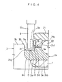
- a bearing device B is explained referring to FIGS. 3 and 4.
- a knuckle 13 that is a member in the vehicle body side is coupled with the flange 25 of the outer ring 21 by bolts.
- the magnetic sensor 9 is fixed on the knuckle 13 in the vehicle inner side of the rolling bearing with a double raceway 2.
- the outer end side of the magnetic sensor 9 in the radial direction thereof is embedded in the knuckle 13, and the inner peripheral side end surface 9a thereof is protruded toward the bearing device B through a through hole 15 formed in the knuckle 13.
- the inner peripheral side end surface 9a of the magnetic sensor 9 is inclined rather toward the inner peripheral side than a position where the pulser ring 8 is disposed so that the magnetic sensor 9 is located in the circumferential groove 24g.
- the whole magnetic sensor 9 Since the whole magnetic sensor 9 is located rather in the vehicle outer side in the axial direction than an abutting portion where the drive shaft 3 abuts the second cylindrical portion 24c of the inner ring 24 so that the magnetic sensor 9 faces the pulser ring 8, the magnetic sensor 9 does not interfere with the drive shaft 3.
- a bearing device C according to still another preferred embodiment of the present invention is explained referring to FIG. 5.
- the inner ring 24 is caulked through plastic deformation where the diameter of the vehicle inner side end portion of the hub wheel 1 is enlarged in advance so that a caulking portion 1a is formed.
- the stepped wall surface 3c of the drive shaft 3 abuts the caulking portion 1a.
- the caulking portion 1a regulates the positions of the bearing device C and the drive shaft 3 in the axial direction.
- the second cylindrical portion 24c of the inner ring 24 also functions as a buffering portion absorbing a stress of the caulking.
- a position of the vehicle inner side end portion of the inner ring 24 and a position of the vehicle inner side end portion of the outer ring 21 are set approximately in the same manner in the axial direction, the magnetic sensor 9 is inserted into the annular space S through a through hole 16 formed in the outer ring 21, and the inner end side of the magnetic sensor 9 in the radial direction is extended up to a position close to the second cylindrical portion 24c of the inner ring 24.
- the vehicle inner side end portion of the inner ring 24 is not projected to the vehicle inner side beyond the vehicle inner side end portion of the outer ring 21.
- the drive shaft 3 may not be directly fitted into the hub wheel 1 and may be once connected with a constant velocity joint which is not shown so that the constant velocity joint is fitted into and coupled with the hub wheel 1.
- the shaft body of the constant velocity joint in this case corresponds to the rotation shaft.
- the bearing device may be provided with two inner rings in the axial direction having raceway grooves for balls 22, 22 in both rows.
- the vehicle inner side end surface of the outer ring 21 and the vehicle inner side end surface of the inner ring 24 may be constructed so that they are located at substantially the same positions in the axial direction.
- various structures such as one in which, for example, the pulser ring 8 is constructed in such a way that recesses and protrusions are alternately formed in the circumferential direction and the condition of the recesses and protrusions is detected by a proximity sensor can be adopted.
Landscapes
- Engineering & Computer Science (AREA)
- General Engineering & Computer Science (AREA)
- Physics & Mathematics (AREA)
- General Physics & Mathematics (AREA)
- Mechanical Engineering (AREA)
- Rolling Contact Bearings (AREA)
Abstract
Description
Claims (8)
- A bearing device comprising:an outer ring member;an inner ring member concentric with said outer ring member; anda pulser ring generating an electrical signal in response to a rotation of said inner ring member,
whereinsaid inner ring member has a first cylindrical portion having an outer peripheral surface on which said pulser ring is fixed and a second cylindrical portion located in a vehicle inner side with respect to said first cylindrical portion and having a smaller outer diameter than that of said first cylindrical portion so as to form a circumferential groove together with said first cylindrical portion for accommodating a radial inner end portion of a magnetic sensor. - A bearing device according to claim 1, wherein said magnetic sensor comprises a detecting element for detecting said electrical signal and a covering member which covers said detecting element, and wherein said covering member has a radial inner end portion to be accommodated in said circumferential groove so that said detecting element faces said pulser ring in an axial direction.
- A bearing device according to claim 2, wherein said covering member is a molded resin.
- A bearing device comprising:a rolling bearing; anda rotation detection device including a pulser ring and a magnetic sensor, said rotation detection device being disposed in a vehicle inner side with respect to said rolling bearing; whereinsaid rolling bearing has an inner ring member having a central hole into which a rotation shaft is fitted in an axial direction and having an inner ring raceway groove on an outer peripheral surface of a vehicle outer side thereof; an outer ring member concentric with said inner ring member, said outer ring member being adapted to be mounted on a vehicle body side and having an outer ring raceway groove facing said inner ring raceway groove in a radial direction on an inner peripheral surface of a vehicle outer side thereof; and a plurality of rolling elements interposed between said inner raceway groove and said outer raceway groove,
whereinsaid inner ring member has a first cylindrical portion facing a vehicle inner side end portion of said outer ring member in a radial direction in a vehicle inner side with respect to said inner ring raceway groove; and a second cylindrical portion projecting toward a vehicle inner side direction with respect to said vehicle inner side end portion of said outer ring member and having a smaller outer diameter than that of said first cylindrical portion,
whereinsaid pulser ring is fixed on an outer peripheral surface of said first cylindrical portion of said inner ring member, and whereinsaid magnetic sensor incorporates a detecting element outputting an electrical signal in response to changes in a relative position between said detecting element and said pulser ring according to a rotation of said pulser ring, and said magnetic sensor has a radial inner end portion, which is arranged in a circumferential groove formed by a difference in level between said first cylindrical portion and said second cylindrical portion of said inner ring member so that said detecting element faces said pulser ring in an axial direction. - A bearing device according to claim 4, further comprising a cover attached to said outer ring member so as to cover an annular space between said outer ring member and said inner ring member from a vehicle inner side, wherein said magnetic sensor is attached to said cover.
- A bearing device according to claim 4, wherein said magnetic sensor is fixed on a knuckle near said outer ring member with said radial outer end side of said magnetic sensor being incorporated in said knuckle.
- A bearing device according to claim 4, wherein said inner ring member comprises a hub wheel having a radially outwardly extending flange in which a wheel is attached on an outer peripheral surface of a vehicle outer side thereof and an inner ring disposed on an outer peripheral surface of a vehicle inner side end portion of said hub wheel, said inner ring having said first and second cylindrical portions.
- A bearing device comprising:a rolling bearing; anda rotation detection device including a pulser ring and a magnetic sensor, said rotation detection device being disposed in a vehicle inner side of said rolling bearing;
whereinsaid rolling bearing has an inner ring member having a central hole into which a rotation shaft is fitted in an axial direction and having an inner ring raceway groove on an outer peripheral surface of a vehicle outer side thereof; an outer ring member concentric with said inner ring member, said outer ring member being adapted to be mounted on a vehicle body side and having an outer ring raceway groove facing said inner ring raceway groove in a radial direction on an inner peripheral surface of a vehicle outer side thereof; and a plurality of rolling elements interposed between the inner raceway groove and the outer raceway groove,
whereinsaid inner ring member has a first cylindrical portion located in a vehicle inner side with respect to said inner ring raceway groove and a second cylindrical portion having a smaller outer diameter than that of said first cylindrical portion in a vehicle inner side of said first cylindrical portion, and whereinsaid outer ring member has a through hole radially extending at a position where said through hole faces said second cylindrical portion of said inner ring member in a radial direction,
whereinsaid pulser ring is fixed on an outer peripheral surface of said first cylindrical portion of said inner ring member, and whereinsaid magnetic sensor incorporates a detecting element outputting an electrical signal in response to changes in a relative position between said detecting element and said pulser ring according to a rotation of said pulser ring, and said magnetic sensor has a radial inner end portion, which is inserted into said through hole of said outer ring member and is accommodated in a circumferential groove formed by a difference in level between said first cylindrical portion and said second cylindrical portion of said inner ring member so that said detecting element faces said pulser ring in an axial direction.
Applications Claiming Priority (2)
| Application Number | Priority Date | Filing Date | Title |
|---|---|---|---|
| JP2001240860 | 2001-08-08 | ||
| JP2001240860A JP2003056583A (en) | 2001-08-08 | 2001-08-08 | Bearing device for axle |
Publications (2)
| Publication Number | Publication Date |
|---|---|
| EP1283421A2 true EP1283421A2 (en) | 2003-02-12 |
| EP1283421A3 EP1283421A3 (en) | 2004-03-10 |
Family
ID=19071408
Family Applications (1)
| Application Number | Title | Priority Date | Filing Date |
|---|---|---|---|
| EP02017530A Ceased EP1283421A3 (en) | 2001-08-08 | 2002-08-06 | Vehicle-use bearing device having rotation detecting device |
Country Status (3)
| Country | Link |
|---|---|
| US (1) | US7033079B2 (en) |
| EP (1) | EP1283421A3 (en) |
| JP (1) | JP2003056583A (en) |
Families Citing this family (2)
| Publication number | Priority date | Publication date | Assignee | Title |
|---|---|---|---|---|
| US6892587B2 (en) * | 2002-03-08 | 2005-05-17 | Ntn Corporation | Rotation detecting device and wheel support bearing assembly utilizing the same |
| JP3858998B2 (en) * | 2003-04-25 | 2006-12-20 | ブラザー工業株式会社 | Image forming apparatus |
Family Cites Families (16)
| Publication number | Priority date | Publication date | Assignee | Title |
|---|---|---|---|---|
| JP3871455B2 (en) * | 1998-12-22 | 2007-01-24 | Ntn株式会社 | Constant velocity joint |
| US4960333A (en) * | 1989-10-16 | 1990-10-02 | The Torrington Company | Antifriction bearing assembly speed sensor |
| US5261752A (en) * | 1991-09-12 | 1993-11-16 | Nsk Ltd. | Bearing having passive pulser ring |
| JP2551705Y2 (en) * | 1991-12-26 | 1997-10-27 | エヌティエヌ株式会社 | Rotational speed detector for wheel bearings |
| DE4243624A1 (en) * | 1991-12-27 | 1993-07-01 | Ntn Toyo Bearing Co Ltd | Revolution rate detector, esp. for vehicle bearings, - contains pulse transducer ring with sensor contg. coil, high frequency voltage source and detector |
| JP3331728B2 (en) * | 1994-03-23 | 2002-10-07 | 日本精工株式会社 | Tapered roller bearing with rotation speed detector |
| JP3231185B2 (en) * | 1994-07-15 | 2001-11-19 | 日本精工株式会社 | Rolling bearing unit with rotation speed detector |
| DE19537039A1 (en) * | 1995-10-05 | 1997-04-10 | Teves Gmbh Alfred | Wheel bearing sensor for vehicle esp. for measuring wheel speed |
| JP3497351B2 (en) * | 1997-03-31 | 2004-02-16 | 日本精工株式会社 | Rolling bearing unit with encoder |
| JPH10324106A (en) * | 1997-05-27 | 1998-12-08 | Ntn Corp | Bearing for axle and mounting structure therefor |
| JP3887887B2 (en) | 1997-06-20 | 2007-02-28 | 日本精工株式会社 | Rolling bearing unit with rotational speed detector |
| JPH1138027A (en) * | 1997-07-18 | 1999-02-12 | Nippon Seiko Kk | Rolling bearing unit with rotation speed detector |
| JP3834977B2 (en) | 1997-12-18 | 2006-10-18 | 日本精工株式会社 | Rolling bearing unit with rotational speed detector |
| US6174088B1 (en) * | 1997-12-15 | 2001-01-16 | Nsk Ltd. | Rolling bearing unit with rotation speed sensor |
| JP2000192949A (en) * | 1998-10-21 | 2000-07-11 | Nsk Ltd | Rotation support device with rotation speed detector |
| FR2823273B1 (en) * | 2001-04-06 | 2003-07-18 | Roulements Soc Nouvelle | BEARING PROVIDED WITH A SENSOR ASSEMBLY SHEATH |
-
2001
- 2001-08-08 JP JP2001240860A patent/JP2003056583A/en active Pending
-
2002
- 2002-08-06 EP EP02017530A patent/EP1283421A3/en not_active Ceased
- 2002-08-06 US US10/213,491 patent/US7033079B2/en not_active Expired - Lifetime
Non-Patent Citations (1)
| Title |
|---|
| None |
Also Published As
| Publication number | Publication date |
|---|---|
| JP2003056583A (en) | 2003-02-26 |
| EP1283421A3 (en) | 2004-03-10 |
| US7033079B2 (en) | 2006-04-25 |
| US20030031392A1 (en) | 2003-02-13 |
Similar Documents
| Publication | Publication Date | Title |
|---|---|---|
| US5975767A (en) | Tone wheel built-in constant velocity joint | |
| JP2005140320A (en) | Drive wheel hub unit | |
| JP2009502657A (en) | Wheel bearing device with end toothed part | |
| JP2006046493A (en) | Rolling bearings for wheels | |
| JP5251922B2 (en) | Drive wheel hub unit | |
| US7033079B2 (en) | Vehicle-use bearing device having rotation detecting device | |
| US5132616A (en) | Polarized magnetic ring for speed sensing bearing assembly | |
| US20050117825A1 (en) | Wheel support bearing assembly with built-in sensor | |
| JP2005140188A (en) | Seal device with sensor and rolling bearing device using the same | |
| JP4547567B2 (en) | SEALING DEVICE AND ROLLING BEARING DEVICE USING THE SAME DEVICE | |
| JP2005076696A (en) | Rolling bearing device | |
| JP2007303522A (en) | Hub unit | |
| JP2006275200A (en) | Cover for rolling bearing device and rolling bearing device using the same | |
| JP2003097580A (en) | Rolling bearing and method for manufacturing the same | |
| JP4693388B2 (en) | Cover with sensor for wheel bearing device | |
| JP4840368B2 (en) | Rotor for rotary encoder and rolling bearing device for wheel having the same | |
| JP4178312B2 (en) | Rolling bearing device | |
| JP2001080307A (en) | Wheel bearing device | |
| JP2007198885A (en) | Rolling bearing device with encoder and sensor | |
| JP2001349334A (en) | Bearing unit for wheel drive | |
| KR102636950B1 (en) | Encoder ring and wheel bearing provided therewith | |
| JP2008144861A (en) | Bearing unit | |
| JP2005140146A (en) | Drive wheel hub unit | |
| JP2010031962A (en) | Rolling bearing device with sensor | |
| JP2005180688A (en) | Arrangement of bearing for wheels |
Legal Events
| Date | Code | Title | Description |
|---|---|---|---|
| PUAI | Public reference made under article 153(3) epc to a published international application that has entered the european phase |
Free format text: ORIGINAL CODE: 0009012 |
|
| AK | Designated contracting states |
Designated state(s): AT BE BG CH CY CZ DE DK EE ES FI FR GB GR IE IT LI LU MC NL PT SE SK TR |
|
| AX | Request for extension of the european patent |
Extension state: AL LT LV MK RO SI |
|
| PUAL | Search report despatched |
Free format text: ORIGINAL CODE: 0009013 |
|
| 17P | Request for examination filed |
Effective date: 20031223 |
|
| AK | Designated contracting states |
Kind code of ref document: A3 Designated state(s): AT BE BG CH CY CZ DE DK EE ES FI FR GB GR IE IT LI LU MC NL PT SE SK TR |
|
| AX | Request for extension of the european patent |
Extension state: AL LT LV MK RO SI |
|
| AKX | Designation fees paid |
Designated state(s): DE FR GB |
|
| RAP1 | Party data changed (applicant data changed or rights of an application transferred) |
Owner name: JTEKT CORPORATION |
|
| 17Q | First examination report despatched |
Effective date: 20070927 |
|
| STAA | Information on the status of an ep patent application or granted ep patent |
Free format text: STATUS: THE APPLICATION HAS BEEN REFUSED |
|
| 18R | Application refused |
Effective date: 20121029 |