EP1283410A2 - Compensation method for an absolute angular position sensor - Google Patents
Compensation method for an absolute angular position sensor Download PDFInfo
- Publication number
- EP1283410A2 EP1283410A2 EP02077893A EP02077893A EP1283410A2 EP 1283410 A2 EP1283410 A2 EP 1283410A2 EP 02077893 A EP02077893 A EP 02077893A EP 02077893 A EP02077893 A EP 02077893A EP 1283410 A2 EP1283410 A2 EP 1283410A2
- Authority
- EP
- European Patent Office
- Prior art keywords
- angular position
- compensation value
- revolution
- determining
- input gear
- Prior art date
- Legal status (The legal status is an assumption and is not a legal conclusion. Google has not performed a legal analysis and makes no representation as to the accuracy of the status listed.)
- Withdrawn
Links
- 238000000034 method Methods 0.000 title claims abstract description 24
- 229910003460 diamond Inorganic materials 0.000 description 4
- 239000010432 diamond Substances 0.000 description 4
- 230000002411 adverse Effects 0.000 description 2
- 238000010586 diagram Methods 0.000 description 2
- 230000007812 deficiency Effects 0.000 description 1
- 239000000463 material Substances 0.000 description 1
- 238000005259 measurement Methods 0.000 description 1
Images
Classifications
-
- G—PHYSICS
- G01—MEASURING; TESTING
- G01D—MEASURING NOT SPECIALLY ADAPTED FOR A SPECIFIC VARIABLE; ARRANGEMENTS FOR MEASURING TWO OR MORE VARIABLES NOT COVERED IN A SINGLE OTHER SUBCLASS; TARIFF METERING APPARATUS; MEASURING OR TESTING NOT OTHERWISE PROVIDED FOR
- G01D5/00—Mechanical means for transferring the output of a sensing member; Means for converting the output of a sensing member to another variable where the form or nature of the sensing member does not constrain the means for converting; Transducers not specially adapted for a specific variable
- G01D5/12—Mechanical means for transferring the output of a sensing member; Means for converting the output of a sensing member to another variable where the form or nature of the sensing member does not constrain the means for converting; Transducers not specially adapted for a specific variable using electric or magnetic means
- G01D5/244—Mechanical means for transferring the output of a sensing member; Means for converting the output of a sensing member to another variable where the form or nature of the sensing member does not constrain the means for converting; Transducers not specially adapted for a specific variable using electric or magnetic means influencing characteristics of pulses or pulse trains; generating pulses or pulse trains
- G01D5/24471—Error correction
- G01D5/24476—Signal processing
-
- G—PHYSICS
- G01—MEASURING; TESTING
- G01D—MEASURING NOT SPECIALLY ADAPTED FOR A SPECIFIC VARIABLE; ARRANGEMENTS FOR MEASURING TWO OR MORE VARIABLES NOT COVERED IN A SINGLE OTHER SUBCLASS; TARIFF METERING APPARATUS; MEASURING OR TESTING NOT OTHERWISE PROVIDED FOR
- G01D5/00—Mechanical means for transferring the output of a sensing member; Means for converting the output of a sensing member to another variable where the form or nature of the sensing member does not constrain the means for converting; Transducers not specially adapted for a specific variable
- G01D5/12—Mechanical means for transferring the output of a sensing member; Means for converting the output of a sensing member to another variable where the form or nature of the sensing member does not constrain the means for converting; Transducers not specially adapted for a specific variable using electric or magnetic means
- G01D5/244—Mechanical means for transferring the output of a sensing member; Means for converting the output of a sensing member to another variable where the form or nature of the sensing member does not constrain the means for converting; Transducers not specially adapted for a specific variable using electric or magnetic means influencing characteristics of pulses or pulse trains; generating pulses or pulse trains
- G01D5/245—Mechanical means for transferring the output of a sensing member; Means for converting the output of a sensing member to another variable where the form or nature of the sensing member does not constrain the means for converting; Transducers not specially adapted for a specific variable using electric or magnetic means influencing characteristics of pulses or pulse trains; generating pulses or pulse trains using a variable number of pulses in a train
- G01D5/2451—Incremental encoders
- G01D5/2452—Incremental encoders incorporating two or more tracks having an (n, n+1, ...) relationship
-
- G—PHYSICS
- G01—MEASURING; TESTING
- G01D—MEASURING NOT SPECIALLY ADAPTED FOR A SPECIFIC VARIABLE; ARRANGEMENTS FOR MEASURING TWO OR MORE VARIABLES NOT COVERED IN A SINGLE OTHER SUBCLASS; TARIFF METERING APPARATUS; MEASURING OR TESTING NOT OTHERWISE PROVIDED FOR
- G01D2205/00—Indexing scheme relating to details of means for transferring or converting the output of a sensing member
- G01D2205/20—Detecting rotary movement
- G01D2205/26—Details of encoders or position sensors specially adapted to detect rotation beyond a full turn of 360°, e.g. multi-rotation
-
- G—PHYSICS
- G01—MEASURING; TESTING
- G01D—MEASURING NOT SPECIALLY ADAPTED FOR A SPECIFIC VARIABLE; ARRANGEMENTS FOR MEASURING TWO OR MORE VARIABLES NOT COVERED IN A SINGLE OTHER SUBCLASS; TARIFF METERING APPARATUS; MEASURING OR TESTING NOT OTHERWISE PROVIDED FOR
- G01D2205/00—Indexing scheme relating to details of means for transferring or converting the output of a sensing member
- G01D2205/20—Detecting rotary movement
- G01D2205/28—The target being driven in rotation by additional gears
Definitions
- the present invention relates to steering wheel absolute angular position sensors.
- One such device includes a relatively large input gear installed on the steering shaft.
- the input gear is meshed with a relatively small output gear.
- a first magnetic field sensor and a second magnetic field sensor are placed near the input gear and the output gear, respectively.
- the gears are constructed so that as they rotate the angular position of the gears is sensed by the sensors.
- the ratio of the input gear to the output gear is chosen so that the gears are out of phase as they rotate through multiple revolutions.
- the signals from the sensors are used to determine the absolute position of the steering shaft.
- the second sensor provides a relatively accurate, high resolution signal representing the angular position of the output gear. This signal, used in conjunction with the out-of-phase angular position signal from the first sensor is used to determine which revolution the steering shaft is in when the signal is received from the second sensor.
- the absolute position of the steering shaft is known.
- the angular position of the output gear is equal to the angular position of the input gear multiplied by the gear ratio.
- the signal from the first sensor can be adversely effected by mechanical noise caused by slight lateral motion of the steering shaft, i.e., wobble.
- the signal from the first sensor can be adversely effected by temperature changes, material magnetic hysteresis, and electrical noise.
- a microprocessor connected to the sensors will incorrectly determine which revolution the input gear is in when the signal is received.
- the microprocessor will incorrectly determine the absolute angular position of the steering shaft.
- the present invention has recognized these prior art drawbacks, and has provided the below-disclosed solutions to one or more of the prior art deficiencies.
- a method for determining an absolute position of a rotating shaft includes determining an angular position compensation value. Then, the absolute angular position of the rotating shaft is determined based on the angular position compensation value. Preferably, an adjusted angular position of an input gear that is connected to the rotating shaft is determined based on the angular position compensation value. The absolute angular position of the rotating shaft is then determined based on the adjusted angular position of the input gear.
- the angular position compensation value is determined for a revolution N + 1 by determining an angular position of the rotating shaft for a revolution N. Also, an angular position of the input gear for the revolution N is determined.
- the method includes determining if the angular position compensation value is greater than a predetermined maximum threshold. If so, the angular position compensation value is established so that is equal to the predetermined maximum threshold. Moreover, it is determined if the angular position compensation value is less than a predetermined minimum threshold. If so, the angular position compensation value is established so that is equal to the predetermined minimum threshold.
- a vehicle control system in another aspect of the present invention, includes an absolute angular position sensor assembly and a microprocessor connected to the sensor assembly.
- the microprocessor includes a program for adjusting a signal representative of an absolute position of a rotating shaft.
- a method for determining an absolute position of a rotating shaft includes providing an input gear and providing an output gear. An angular position compensation value is determined. Moreover, an adjusted angular position of the input gear is determined based on the angular position compensation value. Then, the absolute position of the rotating shaft is determined based on the adjusted angular position of the input gear.
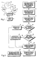
- an absolute angular position sensor assembly is shown and generally designated 10.
- Figure 1 shows that the absolute angular position sensor assembly 10 includes a relatively large input gear 12 meshed with a preferably smaller output gear 14.
- the input gear 12 is installed on or otherwise coupled to a rotating shaft 16, e.g., a steering wheel shaft or other rotating shaft, such that the input gear 12 and the shaft 16 rotate together at the same angular velocity in a direction as indicated by arc 18.
- the output gear 14 rotates about its axis in a direction indicated by arc 20.
- Figure 1 also shows an input gear sensor 22 placed in proximity to the input gear 12 and an output gear sensor 24 placed in proximity to the output gear 14.
- the sensors 22, 24 sense the angular positions of the gears 12, 14.
- the sensors 22, 24 are Hall sensors, MR sensors, or any other sensors well known in the art with similar capabilities, with the input gear 12 and the output gear 14 being constructed so as to be sensed by the sensors 22, 24.
- the first sensor 22 is connected to a microprocessor 26 by electrical line 28.
- the second sensor 24 is also connected to the microprocessor 26 by electrical line 30.
- Figure 1 shows a control system 32, e.g., a steer-by-wire control system connected to the microprocessor 26 by electrical line 34.
- the microprocessor 26 receives signals from the sensors 22, 24 representing the angular positions of the gears 12, 14. Using these signals, the microprocessor 26 determines the absolute position of the rotating shaft 16, as described below.
- the gear ratio of the input gear 12 to the output gear 14 is chosen such that the output gear 14 rotates with a higher angular velocity than the input gear 12. More specifically, the gear ratio between the input gear 12 and the output gear 14 is chosen so that the gear ratio is not a whole number, e.g., the gear ratio is five and two-tenths to one (5.2:1) for measuring five turns of a steering wheel. Since the gear ratio is not a whole number, the gears 12, 14 are out of phase with each other as they rotate.
- the output gear 14 rotates one thousand, eight hundred and seventy-two degrees (1872 ).
- the output gear 14 is out of phase with the input gear 12 by seventy-two degrees (72 ) and with each additional revolution of the input gear 12, the output gear 14 will be out of phase with the input gear 12 by an additional seventy two degrees (72 ).
- the shaft 16 completes five revolutions, the input gear 12 and the output gear 14 are again in phase.
- the present invention has determined that for a gear ratio of 5.2:1, the error tolerance of the signal representing the angular position of the input gear 12 output by the input gear sensor 22 is plus or minus six and nine-tenths degrees (+/- 6.9). As such, if the difference between the angular position of the input gear 12 and the angular position of the output gear 14 divided by the gear ratio is greater than 6.9, the microprocessor 26 will compute the wrong phase and, in turn, compute an incorrect value for the absolute angular position of the rotating shaft 16. In order to prevent the microprocessor 26 from determining an incorrect value for the absolute angular position of the rotating shaft 16, it is necessary to compensate, or adjust, the value of the angular position of the input gear 12 represented by the signal from the input gear sensor 12.
- FIG. 2 a block diagram representing a method for compensating signals from the absolute angular position sensor assembly is shown.
- a signal is received from the output gear sensor 24 that represents the high resolution angular position of the rotating shaft for revolution N.
- a signal is received from the input gear sensor 22 that represents the angular position of the input gear 12.
- an angular position compensation value is determined for revolution N + 1, i.e., the next revolution of the input gear 12.
- the absolute angular position of the rotating shaft 16 is determined for revolution N + 1 at block 52. Then, at block 54, a signal representing the absolute angular position of the rotating shaft 16 is sent from the microprocessor 26 to the control system 32.
- the logic moves to decision diamond 56 where it is determined if the angular position compensation value is less than the negative of the predetermined threshold value. If so, the logic continues to block 56 where the angular position compensation value is set equal to the negative of the predetermined threshold value. Thereafter, the logic moves to block 50 and continues as described above. If, at decision diamond 56, the compensation angle is greater than the negative of the predetermined threshold value, then the logic continues to block 50 and then, proceeds as described above.
- the method for compensating signals from an absolute angular position sensor assembly provides a means for accounting for errors in signals from input gear sensor 22.
- the accuracy of the value determined for the absolute position of the rotating shaft is increased.
Landscapes
- Physics & Mathematics (AREA)
- General Physics & Mathematics (AREA)
- Engineering & Computer Science (AREA)
- Signal Processing (AREA)
- Measurement Of Length, Angles, Or The Like Using Electric Or Magnetic Means (AREA)
- Transmission And Conversion Of Sensor Element Output (AREA)
- Length Measuring Devices With Unspecified Measuring Means (AREA)
Abstract
Description
= Compensation factor ( > 1); and
Claims (18)
- A method for determining an absolute position of a rotating shaft (16), comprising the acts of:determining an angular position compensation value; anddetermining the absolute angular position of the rotating shaft (16) at least partially based on the angular position compensation value.
- The method of Claim 1, further comprising the act of:determining an adjusted angular position of an input gear (12) connected to the rotating shaft (16) at least partially based on the angular position compensation value; anddetermining the absolute angular position of the rotating shaft (16) at least partially based on the adjusted angular position of the input gear (12).
- The method of Claim 1, wherein the angular position compensation value is at least partially determined for a revolution N + 1 by:determining an angular position of the rotating shaft (16) for a revolution N;determining an angular position of the input gear (12) for the revolution N; anddetermining an angular position compensation value for the revolution N.
- The method of Claim 3, wherein the angular position compensation value for the revolution N + 1 is determined as APCVN+1 = (APRSN - AAPIGN) / + APCVN, wherein APCVN+1 is the angular position compensation value for the revolution N + 1, APRSN is the angular position of the rotating shaft (16) for the revolution N, AAPIGN is the adjusted angular position of the input gear (12) for the revolution N, is a compensation factor that is greater than one, and APCVN is angular position compensation value for the revolution N.
- The method of Claim 1, further comprising the act of:determining if the angular position compensation value is greater than a predetermined maximum threshold; andif so, setting the angular position compensation value equal to the predetermined maximum threshold.
- The method of Claim 5, further comprising the act of:determining if the angular position compensation value is less than a predetermined minimum threshold; andif so, setting the angular position compensation value equal to the predetermined minimum threshold.
- A vehicle control system comprising:an absolute angular position sensor assembly (10); anda microprocessor (26) connected to the sensor assembly (10), the microprocessor (26) including a program for adjusting a signal representative of an absolute position of a rotating shaft (16).
- The system of Claim 7, wherein the program comprises:logic means for determining an angular position compensation value; andlogic means determining the absolute angular position of the rotating shaft (16) at least partially based on the angular position compensation value.
- The system of Claim 7, wherein the program comprises:logic means for determining an adjusted angular position of an input gear (12) connected to the rotating shaft (16) at least partially based on the angular position compensation value; andlogic means for determining the absolute angular position of the rotating shaft (16) at least partially based on the adjusted angular position of the input gear (12).
- The system of Claim 8, wherein the microprocessor determines the angular position compensation value for a revolution N + 1 using:logic means for determining an angular position of the rotating shaft (16) for a revolution N;logic means for determining an angular position of the input gear (12) for the revolution N; andlogic means for determining an angular position compensation value for the revolution N.
- The system of Claim 10, wherein the microprocessor (26) determines the angular position compensation value for the revolution N + 1 as APCVN+1 = (APRSN - AAPIGN) / + APCVN, wherein APCVN+1 is the angular position compensation value for the revolution N + 1, APRSN is the angular position of the rotating shaft (16) for the revolution N, AAPIGN is the adjusted angular position of the input gear (12) for the revolution N, is a compensation factor that is greater than one, and APCVN is angular position compensation value for the revolution N.
- The system of Claim 8, wherein the program further comprises:logic means for determining whether the angular position compensation value is greater than a predetermined maximum threshold; andlogic means for setting the angular position compensation value to be equal to the predetermined maximum threshold, if so.
- The system of Claim 12, wherein the program further comprises:logic means for determining whether the angular position compensation value is less than a predetermined minimum threshold; andlogic means for setting the angular position compensation value to be equal to the predetermined minimum threshold, if so.
- A method for determining an absolute position of a rotating shaft (16), comprising the acts of:providing an input gear (12);providing an output gear (14);determining an angular position compensation value;determining an adjusted angular position of the input gear (12) at least partially based on the angular position compensation value; anddetermining the absolute position of the rotating shaft (16) at least partially based on the adjusted angular position of the input gear (12).
- The method of Claim 14, wherein the angular position compensation value is at least partially determined for a revolution N + 1 by:determining an angular position of the rotating shaft (16) for a revolution N;determining an angular position of the input gear (12) for the revolution N; anddetermining an angular position compensation value for the revolution N.
- The method of Claim 15, wherein the angular position compensation value for the revolution N + 1 is determined as APCVN+1 = (APRSN - AAPIGN) / + APCVN, wherein APCVN+1 is the angular position compensation value for the revolution N + 1, APRSN is the angular position of the rotating shaft (16) for the revolution N, AAPIGN is the adjusted angular position of the input gear (12) for the revolution N, is a compensation factor that is greater than one, and APCVN is angular position compensation value for the revolution N.
- The method of Claim 14, further comprising the act of:determining if the angular position compensation value is greater than a predetermined maximum threshold; andif so, setting the angular position compensation value to be equal to the predetermined maximum threshold.
- The method of Claim 17, further comprising the act of:determining if the angular position compensation value is less than a predetermined minimum threshold; andif so, setting the angular position compensation value to be equal to the predetermined minimum threshold.
Applications Claiming Priority (2)
| Application Number | Priority Date | Filing Date | Title |
|---|---|---|---|
| US924875 | 2001-08-08 | ||
| US09/924,875 US6697680B2 (en) | 2001-08-08 | 2001-08-08 | Method for compensating signals from an absolute angular position sensor assembly |
Publications (2)
| Publication Number | Publication Date |
|---|---|
| EP1283410A2 true EP1283410A2 (en) | 2003-02-12 |
| EP1283410A3 EP1283410A3 (en) | 2007-03-14 |
Family
ID=25450858
Family Applications (1)
| Application Number | Title | Priority Date | Filing Date |
|---|---|---|---|
| EP02077893A Withdrawn EP1283410A3 (en) | 2001-08-08 | 2002-07-17 | Compensation method for an absolute angular position sensor |
Country Status (2)
| Country | Link |
|---|---|
| US (1) | US6697680B2 (en) |
| EP (1) | EP1283410A3 (en) |
Families Citing this family (10)
| Publication number | Priority date | Publication date | Assignee | Title |
|---|---|---|---|---|
| JP4260544B2 (en) * | 2003-05-19 | 2009-04-30 | 株式会社日立製作所 | Rotation angle detection device and rotation control device |
| US6865462B2 (en) * | 2003-05-23 | 2005-03-08 | Visteon Global Technologies, Inc. | System and method for initial synchronization of steering wheel and road wheels in a steer-by-wire system |
| US7215112B1 (en) | 2005-11-07 | 2007-05-08 | Delphi Technologies, Inc. | Non-contact linear absolute position sensor |
| FR2899862B1 (en) * | 2006-04-13 | 2009-06-05 | Siemens Vdo Automotive Sas | METHOD AND DEVICE FOR MEASURING THE ANGULAR POSITION, BETWEEN TWO ROTATING STOPS, OF A STEERING WHEEL OF A VEHICLE |
| EP2020840A2 (en) * | 2006-05-24 | 2009-02-11 | TT Electronics Technology Limited | Multiturn rotational sensor |
| US8660754B2 (en) * | 2007-08-17 | 2014-02-25 | Sauer-Danfoss Aps | Steer by wire control system |
| US7960934B2 (en) * | 2008-09-23 | 2011-06-14 | Honeywell International Inc. | Fault-tolerant control system |
| US8297116B2 (en) * | 2010-02-26 | 2012-10-30 | Whetron Electronics Co., Ltd. | Quick removable position sensor |
| DE102014013429A1 (en) * | 2014-09-10 | 2016-03-24 | Audi Ag | Method for exact position determination |
| EP3855257A1 (en) * | 2020-01-22 | 2021-07-28 | Siemens Aktiengesellschaft | Method for monitoring a fail-safe function of sensors in a motor |
Family Cites Families (18)
| Publication number | Priority date | Publication date | Assignee | Title |
|---|---|---|---|---|
| GB8318008D0 (en) * | 1983-07-02 | 1983-08-03 | Lucas Ind Plc | Angular position detector |
| USH104H (en) * | 1985-06-03 | 1986-08-05 | The United States Of America As Represented By The Secretary Of The Army | Digital resolver compensation technique |
| US5041979A (en) * | 1987-04-08 | 1991-08-20 | Motorola, Inc. | Bounded synchronous angle counter |
| US4742332A (en) * | 1987-04-10 | 1988-05-03 | General Motors Corporation | Magnetic shaft angle encoder |
| FR2615940B1 (en) * | 1987-05-27 | 1990-11-30 | Bendix Electronics Sa | METHOD AND DEVICE FOR DETERMINING A REFERENCE POSITION OF A MOBILE |
| US5128883A (en) * | 1991-02-16 | 1992-07-07 | Honeywell Inc. | Method for absolute position determination of multi-speed devices |
| JP3460351B2 (en) * | 1994-02-08 | 2003-10-27 | セイコーエプソン株式会社 | Position detecting device and position detecting method |
| US5540108A (en) * | 1994-02-25 | 1996-07-30 | Advanced Mechanical Technology, Inc. | Multi-axis wheel transducer with angular position detector |
| DE19506938A1 (en) * | 1995-02-28 | 1996-08-29 | Bosch Gmbh Robert | Method and device for measuring the angle of a rotatable body |
| DE29505426U1 (en) * | 1995-03-30 | 1996-05-15 | Siemens Ag | Device for detecting the direction of rotation and checking the plausibility of absolute angular position transmitters with, in particular, serial transmission of recorded actual position values |
| DE19532903A1 (en) * | 1995-09-07 | 1997-03-13 | Teves Gmbh Alfred | Steering angle sensor with absolute value measurement |
| DE19601965A1 (en) * | 1996-01-20 | 1997-07-24 | Teves Gmbh Alfred | Steering angle sensor with revolution counter |
| DE19927146A1 (en) * | 1999-06-15 | 2000-12-21 | Hella Kg Hueck & Co | Position sensor for a motor vehicle |
| DE19942322A1 (en) * | 1999-09-06 | 2001-03-08 | Pwb Ruhlatec Ind Prod Gmbh | Reduction gear for rotating and swiveling movements |
| JP2001174289A (en) * | 1999-12-17 | 2001-06-29 | Alps Electric Co Ltd | Rotation angle detector |
| JP2001241942A (en) * | 2000-02-25 | 2001-09-07 | Alps Electric Co Ltd | Rotation angle detector |
| US6519549B1 (en) * | 2000-07-31 | 2003-02-11 | Delphi Technologies, Inc. | Method and device for determining absolute angular position of a rotating body |
| JP2002213944A (en) * | 2001-01-18 | 2002-07-31 | Niles Parts Co Ltd | Rotation angle measuring device |
-
2001
- 2001-08-08 US US09/924,875 patent/US6697680B2/en not_active Expired - Fee Related
-
2002
- 2002-07-17 EP EP02077893A patent/EP1283410A3/en not_active Withdrawn
Also Published As
| Publication number | Publication date |
|---|---|
| EP1283410A3 (en) | 2007-03-14 |
| US6697680B2 (en) | 2004-02-24 |
| US20030033033A1 (en) | 2003-02-13 |
Similar Documents
| Publication | Publication Date | Title |
|---|---|---|
| US6519549B1 (en) | Method and device for determining absolute angular position of a rotating body | |
| US8453518B2 (en) | Inductive torque sensor | |
| US7472004B2 (en) | Steering angle sensor | |
| US10647353B2 (en) | Electromechanical power steering system, method for determining an absolute angle of rotation, and method for calibrating a measuring device for measuring an absolute angle of rotation | |
| JP4518833B2 (en) | Rotation angle sensor | |
| EP3423333B1 (en) | Ripple minimization by proper as/ts magnet arrangement in electric power assisted steering apparatus | |
| US20100194385A1 (en) | Non-contact multi-turn absolute position magnetic sensor comprising a through-shaft | |
| US6496784B1 (en) | Method for compensating the offset of angle sensors | |
| JP2000296781A (en) | Improvements on electric power steering systems | |
| JP2005077304A (en) | Absolute rotation angle and torque detector | |
| CN102564297A (en) | Sensor system | |
| US20070241742A1 (en) | Rotation angle detection apparatus | |
| US6697680B2 (en) | Method for compensating signals from an absolute angular position sensor assembly | |
| US20030028288A1 (en) | Four wheel steering alignment process | |
| US7201069B2 (en) | Angle sensor | |
| JP2005114481A (en) | Rotation angle sensor | |
| JP4982925B2 (en) | Rotation angle detector | |
| US7325646B2 (en) | Electric power steering apparatus | |
| JP3353538B2 (en) | Position detecting device and position detecting method using the same | |
| JPH11287634A (en) | Vehicle steering sensor | |
| EP2456067B1 (en) | Diagnostic system and method for an electric power steering system | |
| US7254470B2 (en) | Fault tolerant torque sensor signal processing | |
| KR100824027B1 (en) | Steering angle measuring device for vehicle steering shaft and its measuring method | |
| JP2008514476A (en) | How to find the steering angle | |
| US20260056007A1 (en) | Sensor Arrangement and Method for Detecting a Rotational Movement of a Body that can Rotate About a Rotational Axis |
Legal Events
| Date | Code | Title | Description |
|---|---|---|---|
| PUAI | Public reference made under article 153(3) epc to a published international application that has entered the european phase |
Free format text: ORIGINAL CODE: 0009012 |
|
| AK | Designated contracting states |
Designated state(s): AT BE BG CH CY CZ DE DK EE ES FI FR GB GR IE IT LI LU MC NL PT SE SK TR |
|
| AX | Request for extension of the european patent |
Extension state: AL LT LV MK RO SI |
|
| PUAL | Search report despatched |
Free format text: ORIGINAL CODE: 0009013 |
|
| AK | Designated contracting states |
Kind code of ref document: A3 Designated state(s): AT BE BG CH CY CZ DE DK EE ES FI FR GB GR IE IT LI LU MC NL PT SE SK TR |
|
| AX | Request for extension of the european patent |
Extension state: AL LT LV MK RO SI |
|
| 17P | Request for examination filed |
Effective date: 20070914 |
|
| AKX | Designation fees paid |
Designated state(s): DE FR GB |
|
| 17Q | First examination report despatched |
Effective date: 20091223 |
|
| STAA | Information on the status of an ep patent application or granted ep patent |
Free format text: STATUS: THE APPLICATION IS DEEMED TO BE WITHDRAWN |
|
| 18D | Application deemed to be withdrawn |
Effective date: 20100202 |