EP1283169A2 - Method and device for densifying pulverized material - Google Patents
Method and device for densifying pulverized material Download PDFInfo
- Publication number
- EP1283169A2 EP1283169A2 EP02024550A EP02024550A EP1283169A2 EP 1283169 A2 EP1283169 A2 EP 1283169A2 EP 02024550 A EP02024550 A EP 02024550A EP 02024550 A EP02024550 A EP 02024550A EP 1283169 A2 EP1283169 A2 EP 1283169A2
- Authority
- EP
- European Patent Office
- Prior art keywords
- housing
- channels
- bores
- ducts
- feeding
- Prior art date
- Legal status (The legal status is an assumption and is not a legal conclusion. Google has not performed a legal analysis and makes no representation as to the accuracy of the status listed.)
- Withdrawn
Links
Images


Classifications
-
- B—PERFORMING OPERATIONS; TRANSPORTING
- B65—CONVEYING; PACKING; STORING; HANDLING THIN OR FILAMENTARY MATERIAL
- B65B—MACHINES, APPARATUS OR DEVICES FOR, OR METHODS OF, PACKAGING ARTICLES OR MATERIALS; UNPACKING
- B65B63/00—Auxiliary devices, not otherwise provided for, for operating on articles or materials to be packaged
- B65B63/02—Auxiliary devices, not otherwise provided for, for operating on articles or materials to be packaged for compressing or compacting articles or materials prior to wrapping or insertion in containers or receptacles
-
- B—PERFORMING OPERATIONS; TRANSPORTING
- B65—CONVEYING; PACKING; STORING; HANDLING THIN OR FILAMENTARY MATERIAL
- B65B—MACHINES, APPARATUS OR DEVICES FOR, OR METHODS OF, PACKAGING ARTICLES OR MATERIALS; UNPACKING
- B65B63/00—Auxiliary devices, not otherwise provided for, for operating on articles or materials to be packaged
- B65B63/02—Auxiliary devices, not otherwise provided for, for operating on articles or materials to be packaged for compressing or compacting articles or materials prior to wrapping or insertion in containers or receptacles
- B65B63/028—Auxiliary devices, not otherwise provided for, for operating on articles or materials to be packaged for compressing or compacting articles or materials prior to wrapping or insertion in containers or receptacles by pneumatic means
-
- B—PERFORMING OPERATIONS; TRANSPORTING
- B65—CONVEYING; PACKING; STORING; HANDLING THIN OR FILAMENTARY MATERIAL
- B65B—MACHINES, APPARATUS OR DEVICES FOR, OR METHODS OF, PACKAGING ARTICLES OR MATERIALS; UNPACKING
- B65B37/00—Supplying or feeding fluent-solid, plastic, or liquid material, or loose masses of small articles, to be packaged
- B65B37/08—Supplying or feeding fluent-solid, plastic, or liquid material, or loose masses of small articles, to be packaged by rotary feeders
- B65B37/10—Supplying or feeding fluent-solid, plastic, or liquid material, or loose masses of small articles, to be packaged by rotary feeders of screw type
Definitions
- the invention relates to a method according to the preamble of claim 1 and a device according to claim 3 for densifying and compacting pulverized or powdered material.
- US-3,664,385 A describes a method and an apparatus for feeding and compacting finally divided particulate material by means of a rotating screw feeder disposed in a tubular sleeve with a plurality of perforations.
- the sleeve is surrounded by a housing in such a way that at least one closed hollow chamber is provided extending about the sleeve.
- a mesh screen having smaller mesh openings than the size of the particles in the transported material is disposed to the exterior surface of the sleeve.
- a suction pressure is applied along the exterior of the foraminous sleeve to withdraw air from between the particles of the material, and intermittently a gas pressure is applied along the foraminous sleeve to back-flush material from the perforations to prevent clogging thereof.
- EP 0 125 585 A discloses an equipment for the removal of air out of pulveruent materials comprising a packaging vessel having at a distance from the exterior wall a porous lining material substantially over the entire length of the packaging vessel through which lining material it is possible to remove air out of the packaging vessel or to feed pressurised air into the packaging vessel through the space between the exterior wall and the porous lining material.
- the space between the exterior wall and of the lining material is divided air-tightly in the direction of progress of the pulveruent material by means of partition wall, wherein a suction or pressure can be applied to each of the compartments independently from each other.
- Fig. 1 to 6 show an embodiment, wherein channels 23 are provided along the longitudinal extension of a feeding screw 3 so that perforations can be provided throughout the length of a feeding screw.
- Fig. 1 to 5 shows a device comprising four feeding screws 3 which are arranged in parallel to each other in a housing 2 of rectangular shape.
- a rectangular inlet opening 6 is provided on the upper side of the housing for connecting the housing 2 with a not shown filling hopper.
- FIG. 2 The longitudinal sectional view of Fig. 2 shows in more detail a mouth piece 22 between housing 2 and pressing rollers 4, 4'.
- channels 23 are provided in the housing 2, which channels 23 extend essentially along the length of the housing 2.
- Fig. 3 and 9 show three channels 23 which are arranged in parallel to each other in the area of a single feeding screw 3.
- Each channel 23 is connected with a plurality of small diameter bores 24 which extend between the channels 23 and the inner surface 25 of the housing 2.
- two rows of bores 24 are provided along a single channel 23 as can be seen in Fig. 4.
- ducts 26 are provided extending below of the channels 23 essentially perpendicular to these channels 23 in the lower part of the housing 2 as shown in Fig. 4. Vacuum and pressure air is supplied alternatingly to these ducts as indicated by arrows 28.
- Each duct 26 is connected with two channels 23 via vertical extending connecting bores 27.
- the ducts 26 have different length wherein the longest duct 26 extends up to the sixth channel 23 adjacent to the longitudinal center axis of the housing 2.
- a further duct 26 extends up to the fifth channel 23 from both sides of the housing 2 whereas the shortest duct 26 extends from the outside of the housing 2 up to the fourth channel 23 as shown in Fig. 4 and 5.
- each channel 23 is connected via two connecting bore 27 with two ducts 26. In this way vacuum and pressure air is supplied to all of the bores 24 of a channel 23 in an effective way.
- the housing 2 is composed of at least four parts, a lower part 30 provided with channels 23 and ducts 26, an upper part 31 provided with the inlet opening 6 as well front and end parts 32, 33 as shown in Fig. 7.
- the inner surface 25 of the lower part 30 (Fig. 3) is provided with perforations in the form of the bores 24.
- a filter cloth 11 extends over these perforations or bores 24, respectively.
- Said filter cloth 11 is held under tension by means of fastening elements in the form of bars 34 extending along grooves in the lower housing part 30 between the channels 23 and on both sides of the lower housing part 30.
- Said bars 34 are fastened by means of screws 35 on housing part 30 and the filter cloth 11 is clamped between bars 34 and housing part 30.
- a bar 36 of essentially triangular cross-section is provided between the feeding screws 3 to fill the triangular space between adjacent feeding screws as shown in Fig. 5 and 6. The filter cloth 11 is also clamped between this bar 36 and the housing part 30.
- the plate-like lower housing part 30 is provided with cooling passages 37 for circulating of a cooling medium within the housing part 30.
- one passage 37 extends across the channels 23 for supplying cooling medium and a further passage 37' is provided for return flow. Between these passages 37 and 37' connecting passages 38 are provided which extend vertically and along the longitudinal axis of the lower housing part 30 as can be seen in Fig. 6.
- ducts 26 can also be provided in the front and end parts 32 and 33 of the housing for supplying vacuum and compressed air to the channels 23.
- vacuum is applied over a longer period than compressed air. Further it is possible to apply vacuum as well as compressed air in the form of short pulses following each other.
- the described method of alternating application of vacuum and compressed air via a filter can be applied in various apparatuses for densifying and compacting pulverized material, for example, also in packaging assemblies, in which a high filling weight of the packing and a decrease of the pulver volume is important.
- the method and the device according to the invention can be applied in side feeders of extruders for light and aerated pulvers and so on.
Landscapes
- Engineering & Computer Science (AREA)
- Mechanical Engineering (AREA)
- Basic Packing Technique (AREA)
- Filling Or Emptying Of Bunkers, Hoppers, And Tanks (AREA)
- Air Transport Of Granular Materials (AREA)
- Screw Conveyors (AREA)
- Feeding, Discharge, Calcimining, Fusing, And Gas-Generation Devices (AREA)
- Press Drives And Press Lines (AREA)
- Auxiliary Devices For And Details Of Packaging Control (AREA)
- Filtering Of Dispersed Particles In Gases (AREA)
- Disintegrating Or Milling (AREA)
Abstract
Description
- The invention relates to a method according to the preamble of
claim 1 and a device according toclaim 3 for densifying and compacting pulverized or powdered material. - US-3,664,385 A describes a method and an apparatus for feeding and compacting finally divided particulate material by means of a rotating screw feeder disposed in a tubular sleeve with a plurality of perforations. The sleeve is surrounded by a housing in such a way that at least one closed hollow chamber is provided extending about the sleeve. A mesh screen having smaller mesh openings than the size of the particles in the transported material is disposed to the exterior surface of the sleeve. A suction pressure is applied along the exterior of the foraminous sleeve to withdraw air from between the particles of the material, and intermittently a gas pressure is applied along the foraminous sleeve to back-flush material from the perforations to prevent clogging thereof.
- EP 0 125 585 A discloses an equipment for the removal of air out of pulveruent materials comprising a packaging vessel having at a distance from the exterior wall a porous lining material substantially over the entire length of the packaging vessel through which lining material it is possible to remove air out of the packaging vessel or to feed pressurised air into the packaging vessel through the space between the exterior wall and the porous lining material. The space between the exterior wall and of the lining material is divided air-tightly in the direction of progress of the pulveruent material by means of partition wall, wherein a suction or pressure can be applied to each of the compartments independently from each other.
- It is also known to densify pulverized material between to pressing rollers, wherein the pulverized material is pressed into the roller gap by means of., for example, two feeding screws arranged in parallel beside each other and disposed rotratably in a housing, into which the pulverized material is filled via a filling hopper under the effect of gravity. Gas or air contained in the pulverized material has a disturbing effect and can deteriorate the densifying operation between the two pressing rollers.
- To remove air contained in the pulverized material before entering into the roller gap, it is known to provide a filter in the screw housing on a peripheral portion of the feeding screws via which filter vacuum can be applied.
- It is the object of the invention to increase the efficiency of such a device for densifying pulverized material.
- This object is achieved according to the invention by the features in the characterising part of
claims 1 and by the features inclaim 3. - The invention is described in more detail by way of an example in connection with the drawings.
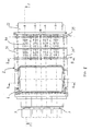
- Fig. 1
- a top view of a preferred embodiment,
- Fig. 2
- a longitudinal sectional view along line F-F in Fig. 1,
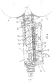
- Fig. 3
- a cross sectional view along line A-A in Fig. 1,
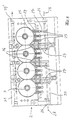
- Fig. 4
- a cross sectional view along line L-L in Fig. 2,
- Fig. 5
- a cross sectional view along line B-B in Fig. 1, and
- Fig. 6
- shows the detail X in Fig. 3 in a larger scale.
- Fig. 1 to 6 show an embodiment, wherein
channels 23 are provided along the longitudinal extension of afeeding screw 3 so that perforations can be provided throughout the length of a feeding screw. - The example according to Fig. 1 to 5 shows a device comprising four
feeding screws 3 which are arranged in parallel to each other in ahousing 2 of rectangular shape. In the top view of Fig. 1 arectangular inlet opening 6 is provided on the upper side of the housing for connecting thehousing 2 with a not shown filling hopper. - The longitudinal sectional view of Fig. 2 shows in more detail a
mouth piece 22 betweenhousing 2 and pressing rollers 4, 4'. - On the lower side of the
housing 2 opposite to the inlet opening 6channels 23 are provided in thehousing 2, whichchannels 23 extend essentially along the length of thehousing 2. Fig. 3 and 9 show threechannels 23 which are arranged in parallel to each other in the area of asingle feeding screw 3. Eachchannel 23 is connected with a plurality ofsmall diameter bores 24 which extend between thechannels 23 and theinner surface 25 of thehousing 2. In this embodiment two rows ofbores 24 are provided along asingle channel 23 as can be seen in Fig. 4. - For supplying vacuum and pressure air to the
channels 23ducts 26 are provided extending below of thechannels 23 essentially perpendicular to thesechannels 23 in the lower part of thehousing 2 as shown in Fig. 4. Vacuum and pressure air is supplied alternatingly to these ducts as indicated byarrows 28. Eachduct 26 is connected with twochannels 23 via vertical extending connectingbores 27. Theducts 26 have different length wherein thelongest duct 26 extends up to thesixth channel 23 adjacent to the longitudinal center axis of thehousing 2. Afurther duct 26 extends up to thefifth channel 23 from both sides of thehousing 2 whereas theshortest duct 26 extends from the outside of thehousing 2 up to thefourth channel 23 as shown in Fig. 4 and 5. - In the shown embodiment six
ducts 26 are provided on each side of thehousing 2, wherein threeducts 26 of different length are provided each for a half of the longitudinal extension of afeeding screw 3. In this way eachchannel 23 is connected via two connectingbore 27 with twoducts 26. In this way vacuum and pressure air is supplied to all of thebores 24 of achannel 23 in an effective way. - The
housing 2 is composed of at least four parts, alower part 30 provided withchannels 23 andducts 26, anupper part 31 provided with the inlet opening 6 as well front andend parts inner surface 25 of the lower part 30 (Fig. 3) is provided with perforations in the form of thebores 24. Afilter cloth 11 extends over these perforations orbores 24, respectively. Saidfilter cloth 11 is held under tension by means of fastening elements in the form ofbars 34 extending along grooves in thelower housing part 30 between thechannels 23 and on both sides of thelower housing part 30. Saidbars 34 are fastened by means ofscrews 35 onhousing part 30 and thefilter cloth 11 is clamped betweenbars 34 andhousing part 30. Abar 36 of essentially triangular cross-section is provided between thefeeding screws 3 to fill the triangular space between adjacent feeding screws as shown in Fig. 5 and 6. Thefilter cloth 11 is also clamped between thisbar 36 and thehousing part 30. - The plate-like
lower housing part 30 is provided withcooling passages 37 for circulating of a cooling medium within thehousing part 30. In this embodiment onepassage 37 extends across thechannels 23 for supplying cooling medium and a further passage 37' is provided for return flow. Between thesepassages 37 and 37' connecting passages 38 are provided which extend vertically and along the longitudinal axis of thelower housing part 30 as can be seen in Fig. 6. - In the
upper part 31 of the housingcorresponding passages 39 and 39' and connectingpassages 40 for circulating of a cooling medium are provided as shown in Fig. 1 and 5. - Despite of the fact that vacuum and compressed air are applied alternatingly over the length of the
feeding screws 3 very high efficiency in densifying pulverized material is achieved by the embodiment according to Fig. 1 to 5 due to the dense arrangement ofchannels 23 and perforations in the form ofbores 24 all over the length of thefeeding screws 3. - Instead of
ducts 26 extending across thechannels 23 ducts can also be provided in the front andend parts channels 23. - According to an embodiment of the invention, vacuum is applied over a longer period than compressed air. Further it is possible to apply vacuum as well as compressed air in the form of short pulses following each other.
- The described method of alternating application of vacuum and compressed air via a filter can be applied in various apparatuses for densifying and compacting pulverized material, for example, also in packaging assemblies, in which a high filling weight of the packing and a decrease of the pulver volume is important. Likewise, the method and the device according to the invention can be applied in side feeders of extruders for light and aerated pulvers and so on.
Claims (8)
- Method for densifying pulverized material, which is transported by means of a feeding screw (3) in a screw housing (2), wherein alternatingly vacuum and compressed air is applied via a filter (11) on the inner circumference of the screw housing (2),
characterized in that
a plurality of feeding screws (3) is provided which are arranged one beneath of the other and
a plurality of channels (23) is provided each extending over the length of a feeding screw and being provided with bores (24) connecting the channels with the inner circumference of the screw housing (2),
wherein alternatingly vacuum and compressed air is applied via ducts (26) extending across the channels and connecting the plurality of channels (23). - Method according to claim 1, wherein the amount of vacuum and the intervals of application of vacuum and compressed air are varied.
- Device for densifying pulverized material comprising
a plurality of feeding screws (3) arranged parallel in a housing (2),
wherein channels (23) extend in a distance from the feeding screws along the feeding screws (3) in the housing (2), and
bores (24) extend between the channels (23) and an inner surface (25) of the housing, which bores (24) are provided along each channel (23) and
wherein the bores (24) are covered by a filter cloth (11) on the inner surface (25) of the housing. - Device according to claim 3 wherein ducts (26) extend essentially perpendicular to the channels (23) in the housing (2), which ducts (26) are connected via connecting bores (27) with one of the channels (23) associated to one feeding screw (3).
- Device according to claims 3 and 4, wherein the filter cloth (11) is fastened on the housing by means of fastening elements in the form of bars (34,36) provided between the rows of bores (24) along each channel (23).
- Device according to the preceding claims 3 to 5, wherein the channels (23) are provided in a plane extending in a distance from the circumference of the feeding screws (3) which are arranged parallel.
- Device according to claim 4, wherein the ducts (26) have different lengths.
- Device according to the preceding claims3 to 7, wherein each channel (23) is connected via two connecting bores (27) with two ducts (26) arranged in a distance along the feeding screws.
Priority Applications (1)
| Application Number | Priority Date | Filing Date | Title |
|---|---|---|---|
| EP02024550A EP1283169A3 (en) | 1999-08-23 | 2000-08-23 | Method and device for densifying pulverized material |
Applications Claiming Priority (4)
| Application Number | Priority Date | Filing Date | Title |
|---|---|---|---|
| EP99116170 | 1999-08-23 | ||
| EP99116170 | 1999-08-23 | ||
| EP00954647A EP1206391B1 (en) | 1999-08-23 | 2000-08-23 | Method and device for densifying pulverized material |
| EP02024550A EP1283169A3 (en) | 1999-08-23 | 2000-08-23 | Method and device for densifying pulverized material |
Related Parent Applications (1)
| Application Number | Title | Priority Date | Filing Date |
|---|---|---|---|
| EP00954647A Division EP1206391B1 (en) | 1999-08-23 | 2000-08-23 | Method and device for densifying pulverized material |
Publications (2)
| Publication Number | Publication Date |
|---|---|
| EP1283169A2 true EP1283169A2 (en) | 2003-02-12 |
| EP1283169A3 EP1283169A3 (en) | 2003-03-05 |
Family
ID=8238798
Family Applications (2)
| Application Number | Title | Priority Date | Filing Date |
|---|---|---|---|
| EP00954647A Expired - Lifetime EP1206391B1 (en) | 1999-08-23 | 2000-08-23 | Method and device for densifying pulverized material |
| EP02024550A Withdrawn EP1283169A3 (en) | 1999-08-23 | 2000-08-23 | Method and device for densifying pulverized material |
Family Applications Before (1)
| Application Number | Title | Priority Date | Filing Date |
|---|---|---|---|
| EP00954647A Expired - Lifetime EP1206391B1 (en) | 1999-08-23 | 2000-08-23 | Method and device for densifying pulverized material |
Country Status (12)
| Country | Link |
|---|---|
| US (1) | US6688345B1 (en) |
| EP (2) | EP1206391B1 (en) |
| JP (1) | JP2003507272A (en) |
| KR (1) | KR20020029381A (en) |
| CN (1) | CN1370123A (en) |
| AT (1) | ATE252022T1 (en) |
| AU (1) | AU6703000A (en) |
| CA (1) | CA2382077A1 (en) |
| DE (1) | DE60005972T2 (en) |
| ES (1) | ES2207543T3 (en) |
| TW (1) | TW495472B (en) |
| WO (1) | WO2001014210A1 (en) |
Cited By (1)
| Publication number | Priority date | Publication date | Assignee | Title |
|---|---|---|---|---|
| CN110834743A (en) * | 2019-11-25 | 2020-02-25 | 无为和泰农业科技有限公司 | Rice processing packagine machine |
Families Citing this family (6)
| Publication number | Priority date | Publication date | Assignee | Title |
|---|---|---|---|---|
| RU2502661C1 (en) * | 2012-08-27 | 2013-12-27 | Закрытое Акционерное Общество "Твин Трейдинг Компани" | Air vacuum transfer of loose materials with high weight concentration |
| RU2535821C1 (en) * | 2013-10-31 | 2014-12-20 | Закрытое Акционерное Общество "Твин Трейдинг Компани" | Air vacuum device for transfer of loose materials with high weight concentration |
| CN105599927A (en) * | 2016-01-20 | 2016-05-25 | 湖州浙宝冶金辅料有限公司 | Totally-closed packaging system for high calcium powder |
| DE102016207549A1 (en) * | 2016-05-02 | 2017-11-02 | Rovema Gmbh | Process for the continuous or intermittent production of tubular bag packaging and tubular bag machines |
| IT201600091025A1 (en) * | 2016-09-08 | 2018-03-08 | Ica Spa | SYSTEM AND METHOD FOR PACKAGING POWDERS |
| KR102830938B1 (en) | 2019-09-04 | 2025-07-08 | 삼성전자주식회사 | Clothing Dryer |
Citations (2)
| Publication number | Priority date | Publication date | Assignee | Title |
|---|---|---|---|---|
| US3664385A (en) | 1971-02-12 | 1972-05-23 | Carter Eng Co | Method and apparatus for feeding and compacting finely divided particulate material |
| EP0125585A1 (en) | 1983-05-11 | 1984-11-21 | Erkomat Oy | Equipment for the removal of air out of pulverulent materials |
Family Cites Families (8)
| Publication number | Priority date | Publication date | Assignee | Title |
|---|---|---|---|---|
| GB668394A (en) * | 1948-05-01 | 1952-03-19 | Monsanto Chemicals | Improvements in or relating to method of and apparatus for densifying dry powdered solids |
| CH533537A (en) * | 1970-12-21 | 1973-02-15 | Gericke & Co | Device for filling a container with compacted, powdery material |
| IT938559B (en) * | 1971-12-13 | 1973-01-25 | Acma Spa | PERFECTION TO THE DOSAGE DISPENSER OF NON-SLIDING POWDERULENT PRODUCTS IN MULTIPLE PACKAGING MACHINES |
| FR2377937A1 (en) * | 1977-01-20 | 1978-08-18 | Alfa Laval Ag | METHOD AND DEVICE FOR DEAERATION OF POWDERS, SUCH AS MILK POWDERS |
| GB2034591B (en) * | 1978-11-07 | 1983-03-30 | Pimi Spa | Compacting device for particulate material |
| US5538053A (en) * | 1989-09-15 | 1996-07-23 | Better Agricultural Goals Corporation | Vacuum densifier with auger |
| US5894871A (en) * | 1997-08-26 | 1999-04-20 | Greer; David L. | Sand hopper for filling bags |
| US6102088A (en) * | 1997-09-03 | 2000-08-15 | Xerox Corporation | Vacuum valve shutoff for particulate filling system |
-
2000
- 2000-08-23 AU AU67030/00A patent/AU6703000A/en not_active Abandoned
- 2000-08-23 CN CN00811924A patent/CN1370123A/en active Pending
- 2000-08-23 EP EP00954647A patent/EP1206391B1/en not_active Expired - Lifetime
- 2000-08-23 KR KR1020027002052A patent/KR20020029381A/en not_active Withdrawn
- 2000-08-23 WO PCT/EP2000/008237 patent/WO2001014210A1/en not_active Ceased
- 2000-08-23 AT AT00954647T patent/ATE252022T1/en not_active IP Right Cessation
- 2000-08-23 JP JP2001518318A patent/JP2003507272A/en active Pending
- 2000-08-23 ES ES00954647T patent/ES2207543T3/en not_active Expired - Lifetime
- 2000-08-23 DE DE60005972T patent/DE60005972T2/en not_active Expired - Fee Related
- 2000-08-23 CA CA002382077A patent/CA2382077A1/en not_active Abandoned
- 2000-08-23 EP EP02024550A patent/EP1283169A3/en not_active Withdrawn
- 2000-09-02 TW TW089117969A patent/TW495472B/en not_active IP Right Cessation
-
2002
- 2002-08-06 US US10/069,903 patent/US6688345B1/en not_active Expired - Fee Related
Patent Citations (2)
| Publication number | Priority date | Publication date | Assignee | Title |
|---|---|---|---|---|
| US3664385A (en) | 1971-02-12 | 1972-05-23 | Carter Eng Co | Method and apparatus for feeding and compacting finely divided particulate material |
| EP0125585A1 (en) | 1983-05-11 | 1984-11-21 | Erkomat Oy | Equipment for the removal of air out of pulverulent materials |
Cited By (1)
| Publication number | Priority date | Publication date | Assignee | Title |
|---|---|---|---|---|
| CN110834743A (en) * | 2019-11-25 | 2020-02-25 | 无为和泰农业科技有限公司 | Rice processing packagine machine |
Also Published As
| Publication number | Publication date |
|---|---|
| AU6703000A (en) | 2001-03-19 |
| DE60005972D1 (en) | 2003-11-20 |
| US6688345B1 (en) | 2004-02-10 |
| WO2001014210A1 (en) | 2001-03-01 |
| ES2207543T3 (en) | 2004-06-01 |
| EP1206391A1 (en) | 2002-05-22 |
| JP2003507272A (en) | 2003-02-25 |
| KR20020029381A (en) | 2002-04-18 |
| EP1283169A3 (en) | 2003-03-05 |
| CA2382077A1 (en) | 2001-03-01 |
| ATE252022T1 (en) | 2003-11-15 |
| EP1206391B1 (en) | 2003-10-15 |
| TW495472B (en) | 2002-07-21 |
| CN1370123A (en) | 2002-09-18 |
| DE60005972T2 (en) | 2004-09-09 |
Similar Documents
| Publication | Publication Date | Title |
|---|---|---|
| EP0089114A2 (en) | A dust collector | |
| KR100952181B1 (en) | High speed charging method and device of composite cigarette filter | |
| US6688345B1 (en) | Method and device for densifying pulverized material | |
| WO2011117981A1 (en) | Cigarette bundle supply device | |
| US5846300A (en) | Fabric filter with gas inlet geometry and method | |
| CN101573168A (en) | A filter inlet | |
| US20250099892A1 (en) | Modular filter system with shake and pulse cleaning for dusty enclosures | |
| CZ273996A3 (en) | Apparatus for separating heavy particles of material from lighter particles | |
| WO1986007290A1 (en) | Screening apparatus with integrated distributing and segregating device | |
| CN217164846U (en) | Low-gangue-content material gradient flow sorting machine | |
| GB2048723A (en) | Screen for a screening machine | |
| AU762635B2 (en) | Dust filter | |
| SU906627A1 (en) | Drum tyre screen | |
| PL202408B1 (en) | Device for treating sheet materials using pressurised water jets | |
| US5251763A (en) | Conveying apparatus and separation apparatus | |
| SE452216B (en) | SET AND UNIT FOR CHARGING A FILTERING TANK WITH ADSORBORING, PARTICULATE FILTER MATERIAL | |
| CA1173084A (en) | Feeder/distributor apparatus for granular coal | |
| JPH03505777A (en) | Power plant with ash cooler with screw conveyor | |
| CA2010897A1 (en) | Screening machine | |
| JP3832905B2 (en) | Pulsating air flow type powder mixing device | |
| CN107377367B (en) | High-efficient rose box | |
| JPH03500848A (en) | Device for pneumatic conveyance of particulate materials such as tobacco | |
| PL155757B1 (en) | Dust collection filter for use in mines | |
| US6770139B2 (en) | Device for dusting products | |
| CZ257994A3 (en) | Tangential separation chamber |
Legal Events
| Date | Code | Title | Description |
|---|---|---|---|
| PUAI | Public reference made under article 153(3) epc to a published international application that has entered the european phase |
Free format text: ORIGINAL CODE: 0009012 |
|
| PUAL | Search report despatched |
Free format text: ORIGINAL CODE: 0009013 |
|
| AC | Divisional application: reference to earlier application |
Ref document number: 1206391 Country of ref document: EP Kind code of ref document: P |
|
| AK | Designated contracting states |
Designated state(s): AT BE CH CY DE DK ES FI FR GB GR IE IT LI LU MC NL PT SE |
|
| AK | Designated contracting states |
Designated state(s): AT BE CH CY DE DK ES FI FR GB GR IE IT LI LU MC NL PT SE Kind code of ref document: A3 Designated state(s): AT BE CH CY DE DK ES FI FR GB GR IE IT LI LU MC NL PT SE |
|
| RIC1 | Information provided on ipc code assigned before grant |
Ipc: 7B 65G 33/18 B Ipc: 7B 65B 37/10 B Ipc: 7B 65B 63/02 B Ipc: 7B 65B 1/12 A |
|
| 17P | Request for examination filed |
Effective date: 20021104 |
|
| 17Q | First examination report despatched |
Effective date: 20030909 |
|
| AKX | Designation fees paid |
Designated state(s): AT BE CH CY DE DK ES FI FR GB GR IE IT LI LU MC NL PT SE |
|
| GRAP | Despatch of communication of intention to grant a patent |
Free format text: ORIGINAL CODE: EPIDOSNIGR1 |
|
| STAA | Information on the status of an ep patent application or granted ep patent |
Free format text: STATUS: THE APPLICATION IS DEEMED TO BE WITHDRAWN |
|
| 18D | Application deemed to be withdrawn |
Effective date: 20040918 |