EP1282891B1 - Remote control and power system - Google Patents
Remote control and power system Download PDFInfo
- Publication number
- EP1282891B1 EP1282891B1 EP01928092A EP01928092A EP1282891B1 EP 1282891 B1 EP1282891 B1 EP 1282891B1 EP 01928092 A EP01928092 A EP 01928092A EP 01928092 A EP01928092 A EP 01928092A EP 1282891 B1 EP1282891 B1 EP 1282891B1
- Authority
- EP
- European Patent Office
- Prior art keywords
- signal
- electrical
- optical
- piezoelectric
- operable
- Prior art date
- Legal status (The legal status is an assumption and is not a legal conclusion. Google has not performed a legal analysis and makes no representation as to the accuracy of the status listed.)
- Expired - Lifetime
Links
- 230000003287 optical effect Effects 0.000 claims abstract description 28
- 239000013307 optical fiber Substances 0.000 claims abstract description 7
- 230000004044 response Effects 0.000 claims description 6
- 239000007787 solid Substances 0.000 claims description 4
- 229910002601 GaN Inorganic materials 0.000 claims description 3
- JMASRVWKEDWRBT-UHFFFAOYSA-N Gallium nitride Chemical compound [Ga]#N JMASRVWKEDWRBT-UHFFFAOYSA-N 0.000 claims description 3
- 239000004065 semiconductor Substances 0.000 claims description 3
- 238000006243 chemical reaction Methods 0.000 abstract 1
- 230000008901 benefit Effects 0.000 description 5
- 230000005540 biological transmission Effects 0.000 description 4
- 239000000446 fuel Substances 0.000 description 4
- 230000007423 decrease Effects 0.000 description 3
- 239000002828 fuel tank Substances 0.000 description 3
- 238000006073 displacement reaction Methods 0.000 description 2
- 229910052451 lead zirconate titanate Inorganic materials 0.000 description 2
- 239000000463 material Substances 0.000 description 2
- 239000010409 thin film Substances 0.000 description 2
- RYGMFSIKBFXOCR-UHFFFAOYSA-N Copper Chemical compound [Cu] RYGMFSIKBFXOCR-UHFFFAOYSA-N 0.000 description 1
- 239000000919 ceramic Substances 0.000 description 1
- 229910010293 ceramic material Inorganic materials 0.000 description 1
- 230000001010 compromised effect Effects 0.000 description 1
- 229910052802 copper Inorganic materials 0.000 description 1
- 239000010949 copper Substances 0.000 description 1
- 230000003247 decreasing effect Effects 0.000 description 1
- 238000005553 drilling Methods 0.000 description 1
- 230000005674 electromagnetic induction Effects 0.000 description 1
- 238000004880 explosion Methods 0.000 description 1
- 239000000835 fiber Substances 0.000 description 1
- 238000011065 in-situ storage Methods 0.000 description 1
- HFGPZNIAWCZYJU-UHFFFAOYSA-N lead zirconate titanate Chemical compound [O-2].[O-2].[O-2].[O-2].[O-2].[Ti+4].[Zr+4].[Pb+2] HFGPZNIAWCZYJU-UHFFFAOYSA-N 0.000 description 1
- 230000007246 mechanism Effects 0.000 description 1
- 230000004048 modification Effects 0.000 description 1
- 238000012986 modification Methods 0.000 description 1
- 230000005855 radiation Effects 0.000 description 1
- 230000003595 spectral effect Effects 0.000 description 1
Images
Classifications
-
- H—ELECTRICITY
- H04—ELECTRIC COMMUNICATION TECHNIQUE
- H04B—TRANSMISSION
- H04B10/00—Transmission systems employing electromagnetic waves other than radio-waves, e.g. infrared, visible or ultraviolet light, or employing corpuscular radiation, e.g. quantum communication
- H04B10/80—Optical aspects relating to the use of optical transmission for specific applications, not provided for in groups H04B10/03 - H04B10/70, e.g. optical power feeding or optical transmission through water
- H04B10/806—Arrangements for feeding power
- H04B10/807—Optical power feeding, i.e. transmitting power using an optical signal
-
- G—PHYSICS
- G08—SIGNALLING
- G08C—TRANSMISSION SYSTEMS FOR MEASURED VALUES, CONTROL OR SIMILAR SIGNALS
- G08C23/00—Non-electrical signal transmission systems, e.g. optical systems
- G08C23/06—Non-electrical signal transmission systems, e.g. optical systems through light guides, e.g. optical fibres
Definitions
- This invention relates to a system for controlling and providing electrical power to an electrical device at a remote point. More especially, although not exclusively, the invention concerns a remote mechanical actuation system for remotely controlling and providing electrical power to a piezoelectric mechanical actuator or micro-machined electrical system.
- the wires are typically made of copper they are therefore susceptible to failure by fatigue making then unsuited to high vibration environments.
- the actuator such as for example an oil or gas well valve which can be located several kilometres from the control system (typically the well head)
- the length of the connecting wires can give rise to additional problems. These include limitations on the electrical signal due to the time constant of the transmission line and resistive loss, both of which decrease the overall system efficiency.
- the electro-mechanical actuator has no rubbing surfaces such as bearings or pivots, which are prone to wear and for this reason piezoelectric mechanical actuators are favoured.
- piezoelectric actuator As is known in order for a piezoelectric actuator to deliver any significant mechanical displacement (e.g. 0.1% strain) this requires the application of roughly 1,000 volts per millimetre of thickness of piezoelectric ceramic material and they are thus inherently high voltage devices.
- the required drive voltage can be decreased by using multiple thin films of piezoelectric material the reliability of the actuator can be compromised.
- the circuitry comprises an inverter (dc to ac converter) to convert the direct current signal into an alternating current signal, a transformer to step the voltage up to the desired value and a rectification circuit to convert the signal back to a direct current signal.
- inverter dc to ac converter
- transformer to step the voltage up to the desired value
- rectification circuit to convert the signal back to a direct current signal.
- the present invention has arisen in endeavour to provide a remote mechanical actuation system which in part, at least, overcomes the limitations of the known systems.
- a system for controlling and providing electrical power to an electrical device at a remote point comprising: a light source operable to produce an intensity modulated optical signal in response to a control signal, an optical fibre for guiding said optical signal to a photodetector located at said remote point, said photodetector being operable to produce an electrical signal in response to said optical signal and a piezoelectric transformer connected to said photodetector for converting said electrical signal into a higher voltage second electrical signal for controlling and providing power to the electrical device.
- the electrical device comprises a piezoelectric mechanical actuator, micro-machined electrical system or a gallium nitride semiconductor and device.
- the light source comprises a solid state laser and the optical signal is produced by directly modulating the laser using the control signal.
- the laser is operable to produce a continuous optical output and further comprising optical modulation means operable to modulate said continuous optical output in response to said control signal.
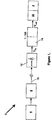
- the system 2 comprises, in serial connections, a controller 6, a solid state laser 8, an optical fibre 10, a photodetector 12 a piezoelectric transformer 14 and a piezoelectric mechanical actuator 16.
- the controller 6, which might typically comprise a part of the aircraft's control system, is operable to produce a varying (typically up to 100kHz) direct current electrical control signal, which as will be described, is used to control and provide electrical power to operate the piezoelectric mechanical actuator 16 which is mechanically coupled to the fuel valve 4.
- the electrical control signal is used to drive the laser 8 such as to produce an intensity modulated optical signal whose intensity is proportional to the magnitude of the control signal.
- the solid state laser is a 980nm device and produces an optical output of up to 5W.
- the output of the laser 8 is coupled into the optical fibre 10, which can be mono-mode or multi-mode, and the optical signal guided by the fibre 10 to the photodetector 12 which converts the optical signal back into a second varying direct current electrical signal.
- the photodetector 12 is an array of photodiodes and the second signal has a magnitude of between 3 and 6 volts.
- the second electrical signal is applied to the primary of the piezoelectric transformer 14 which transforms the signal into a high voltage, typically 300-600V, varying direct current signal which is used to directly drive the piezoelectric actuator 16.
- a piezoelectric transformer generally comprises an elongate bar of piezoelectric material, often a ceramic of lead zirconate titanate (PZT), having primary and secondary regions.
- PZT lead zirconate titanate
- a varying direct current electrical signal applied to the primary region excites vibrations therein which are mechanically coupled to the secondary region to induce mechanical stress in the region which are in converted back into a varying direct current electrical signal of a different voltage.
- the voltage multiplication factor of the transformer is determined by the aspect ratio of the output electrode on the secondary region.
- the multiplication factor of the transformer is typically more than one hundred times.
- a piezoelectric transformer can directly transform a varying direct current signal into a different voltage varying direct current signal without the need for inversion and rectification.
- the optically controlled remote mechanical actuation system described has a number of advantages over the known arrangements. Firstly since the control signal is transmitted to the actuator in the form of an optical signal rather than an electrical signal this makes the system intrinsically safe for use in high risk environments and is further immune to interference from external electrical and magnetic fields.
- the fuel valve 4 will be in close proximity to, or possibly located inside, the aircraft's fuel tank and it is probable that the control lines (optical fibres) will have to be routed through the fuel tanks which are usually distributed throughout the wings. Consequently there is a high risk of explosion should the mechanical actuation system fail or produce sparks.
- a further advantage of using an optical fibre rather than conducting wires is that they are extremely small and mechanically very robust making them ideally suited to aeronautic or other applications where mass is of prime concern.
- piezoelectric transformer to directly drive the piezoelectric mechanical actuator offers a number of advantages. Firstly it eliminates the need for the electronic circuitry, inverter and rectifier, normally required when using a conventional magnetic transformer thereby further reducing the system volume and mass. Secondly Piezoelectric transformers are particularly effective where high (>100) voltage multiplication ratios are required as is the case when it is desired to drive a piezoelectric actuator from a low voltage control signal. Additionally they are physically smaller than an equivalent conventional wound transformer and their higher efficiency is preserved irrespective of size and drive frequency. In contrast a conventional magnetic transformer functions less efficiently as the size decreases and frequency increases.
- a particular advantage of the system of the present invention is the system's inherent linearity.
- the displacement produced by the actuator is proportional to the magnitude of the high voltage drive signal which in turn is proportional to the intensity of the optical control signal and the magnitude of the original control signal.
- the system of the present application is not restricted to the specific application described and can accordingly be applied to other applications.
- the system to control the valves used to regulate the flow of oil and/or gas from wells. After drilling the access hole, these valves are inserted into the pipe where they remain in situ for the life of the oil field, typically 15 years.
- the temperature of the field can typically be 200°C and the valve can easily be 20km or more below the well head. Since an optical fibre typically has a loss of a few tenths of a decibel per kilometre it is practical in such an application to transmit the control and electrical power in the form of an optical signal.
- piezoelectric transformer and actuator provide the advantage that both are capable of reliable operation up to their curie temperature (up to 400°C).
- the photo detector is capable of operation up to 250°C.
- typical well temperatures exceed the upper limit for wound transformers and the associated drive circuitry (even military grade electronic components are usually only rated to 150°C).
- the use of a piezoelectric transformer and actuator combination is particularly preferred, the use of a piezoelectric transformer in this way to enable the efficient transmission of both control information and electric power to an electrical device located at a remote point is considered to be inventive in its own right. Accordingly in other embodiments the system can be used to control and provide electrical power to other forms of actuators or devices which require a high drive voltage such as micro-machined electrical systems (MEMS) or a gallium nitride semiconductor device which requires a voltage supply of 100V.
- MEMS micro-machined electrical systems
- a gallium nitride semiconductor device which requires a voltage supply of 100V.
Landscapes
- Physics & Mathematics (AREA)
- General Physics & Mathematics (AREA)
- Electromagnetism (AREA)
- Engineering & Computer Science (AREA)
- Computer Networks & Wireless Communication (AREA)
- Signal Processing (AREA)
- Mechanical Light Control Or Optical Switches (AREA)
- General Electrical Machinery Utilizing Piezoelectricity, Electrostriction Or Magnetostriction (AREA)
Abstract
Description
- This invention relates to a system for controlling and providing electrical power to an electrical device at a remote point. More especially, although not exclusively, the invention concerns a remote mechanical actuation system for remotely controlling and providing electrical power to a piezoelectric mechanical actuator or micro-machined electrical system.
- There are many applications where it is required to provide mechanical movement remote from a control system such as for example the laser tracking mechanism in CD players and control flaps on aircraft to name but two. In almost every system the control system transmits. an electrical signal to an electro-mechanical actuator using conductive wires. This electrical signal, which often provides both the electrical power and control information, is converted into a mechanical moment by the electro-mechanical actuator which typically comprises an electric motor, electromagnet, piezoelectric or electrostatic mechanical actuator.
- Whilst such an arrangement is perfectly adequate for many applications it does have inherent limitations associated with the conducting wires making it unsuited for certain applications. For example corruption of the electrical signal can arise from electromagnetic induction when the wires are run through electrically and/or magnetically noisy environments. Conversely, when it is required to run the wires through electrically and/or magnetically quiet environments, transmission of the electrical signal can result in the emission of radiation, which can interfere with the operation of other electrical systems in the vicinity of the wires. To operate the electro-mechanical actuator often requires the transmission of high power electrical signals and this can result in the wires having a diameter which is unacceptable in applications where space and/or weight is of prime concern such as for example in aeronautical applications. Furthermore since the wires are typically made of copper they are therefore susceptible to failure by fatigue making then unsuited to high vibration environments. Finally in applications where the control system is a long distance from the actuator, such as for example an oil or gas well valve which can be located several kilometres from the control system (typically the well head), the length of the connecting wires can give rise to additional problems. These include limitations on the electrical signal due to the time constant of the transmission line and resistive loss, both of which decrease the overall system efficiency.
- For high reliability, it is preferred that the electro-mechanical actuator has no rubbing surfaces such as bearings or pivots, which are prone to wear and for this reason piezoelectric mechanical actuators are favoured. As is known in order for a piezoelectric actuator to deliver any significant mechanical displacement (e.g. 0.1% strain) this requires the application of roughly 1,000 volts per millimetre of thickness of piezoelectric ceramic material and they are thus inherently high voltage devices. Although the required drive voltage can be decreased by using multiple thin films of piezoelectric material the reliability of the actuator can be compromised. To avoid the need to transmit high voltage signals it is known to transmit the electrical signal as a direct current signal of a few volts and to convert it to a direct current electrical drive signal of between a 100 and 1000 volts using appropriate circuitry. Typically the circuitry comprises an inverter (dc to ac converter) to convert the direct current signal into an alternating current signal, a transformer to step the voltage up to the desired value and a rectification circuit to convert the signal back to a direct current signal. Such circuitry decreases the overall efficiency and reliability of the system.
- The present invention has arisen in endeavour to provide a remote mechanical actuation system which in part, at least, overcomes the limitations of the known systems.
- According to the present invention there is provided a system for controlling and providing electrical power to an electrical device at a remote point said system comprising: a light source operable to produce an intensity modulated optical signal in response to a control signal, an optical fibre for guiding said optical signal to a photodetector located at said remote point, said photodetector being operable to produce an electrical signal in response to said optical signal and a piezoelectric transformer connected to said photodetector for converting said electrical signal into a higher voltage second electrical signal for controlling and providing power to the electrical device.
- Preferably the electrical device comprises a piezoelectric mechanical actuator, micro-machined electrical system or a gallium nitride semiconductor and device.
- Advantageously the light source comprises a solid state laser and the optical signal is produced by directly modulating the laser using the control signal. Alternatively the laser is operable to produce a continuous optical output and further comprising optical modulation means operable to modulate said continuous optical output in response to said control signal.
- In order that the invention may be better understood a remote mechanical actuation system in accordance with the invention will now be described by way of example only with reference to the accompanying drawing.
- Referring to the drawing there is shown a system 2 for remotely controlling and providing electrical power to an
aircraft fuel valve 4 to regulate the flow of fuel between the fuel tanks and the engine/s. - The system 2 comprises, in serial connections, a
controller 6, asolid state laser 8, anoptical fibre 10, a photodetector 12 apiezoelectric transformer 14 and a piezoelectricmechanical actuator 16. Thecontroller 6, which might typically comprise a part of the aircraft's control system, is operable to produce a varying (typically up to 100kHz) direct current electrical control signal, which as will be described, is used to control and provide electrical power to operate the piezoelectricmechanical actuator 16 which is mechanically coupled to thefuel valve 4. The electrical control signal is used to drive thelaser 8 such as to produce an intensity modulated optical signal whose intensity is proportional to the magnitude of the control signal. In the embodiment described the solid state laser is a 980nm device and produces an optical output of up to 5W. The output of thelaser 8 is coupled into theoptical fibre 10, which can be mono-mode or multi-mode, and the optical signal guided by thefibre 10 to thephotodetector 12 which converts the optical signal back into a second varying direct current electrical signal. - Typically the
photodetector 12 is an array of photodiodes and the second signal has a magnitude of between 3 and 6 volts. - The second electrical signal is applied to the primary of the
piezoelectric transformer 14 which transforms the signal into a high voltage, typically 300-600V, varying direct current signal which is used to directly drive thepiezoelectric actuator 16. As is known a piezoelectric transformer generally comprises an elongate bar of piezoelectric material, often a ceramic of lead zirconate titanate (PZT), having primary and secondary regions. In operation a varying direct current electrical signal applied to the primary region excites vibrations therein which are mechanically coupled to the secondary region to induce mechanical stress in the region which are in converted back into a varying direct current electrical signal of a different voltage. The voltage multiplication factor of the transformer is determined by the aspect ratio of the output electrode on the secondary region. For the embodiment described, which utilises a bulk piezoelectric actuator rather than a thin film device, the multiplication factor of the transformer is typically more than one hundred times. Unlike a conventional (magnetic) transformer a piezoelectric transformer can directly transform a varying direct current signal into a different voltage varying direct current signal without the need for inversion and rectification. - It will be appreciated that the optically controlled remote mechanical actuation system described has a number of advantages over the known arrangements. Firstly since the control signal is transmitted to the actuator in the form of an optical signal rather than an electrical signal this makes the system intrinsically safe for use in high risk environments and is further immune to interference from external electrical and magnetic fields. For example in the embodiment described the
fuel valve 4 will be in close proximity to, or possibly located inside, the aircraft's fuel tank and it is probable that the control lines (optical fibres) will have to be routed through the fuel tanks which are usually distributed throughout the wings. Consequently there is a high risk of explosion should the mechanical actuation system fail or produce sparks. A further advantage of using an optical fibre rather than conducting wires is that they are extremely small and mechanically very robust making them ideally suited to aeronautic or other applications where mass is of prime concern. - Further the use of piezoelectric transformer to directly drive the piezoelectric mechanical actuator offers a number of advantages. Firstly it eliminates the need for the electronic circuitry, inverter and rectifier, normally required when using a conventional magnetic transformer thereby further reducing the system volume and mass. Secondly Piezoelectric transformers are particularly effective where high (>100) voltage multiplication ratios are required as is the case when it is desired to drive a piezoelectric actuator from a low voltage control signal. Additionally they are physically smaller than an equivalent conventional wound transformer and their higher efficiency is preserved irrespective of size and drive frequency. In contrast a conventional magnetic transformer functions less efficiently as the size decreases and frequency increases.
- A particular advantage of the system of the present invention is the system's inherent linearity. As it will be appreciated the displacement produced by the actuator is proportional to the magnitude of the high voltage drive signal which in turn is proportional to the intensity of the optical control signal and the magnitude of the original control signal.
- It will be appreciated that the system of the present application is not restricted to the specific application described and can accordingly be applied to other applications. In a second example it is envisaged to use the system to control the valves used to regulate the flow of oil and/or gas from wells. After drilling the access hole, these valves are inserted into the pipe where they remain in situ for the life of the oil field, typically 15 years. The temperature of the field can typically be 200°C and the valve can easily be 20km or more below the well head. Since an optical fibre typically has a loss of a few tenths of a decibel per kilometre it is practical in such an application to transmit the control and electrical power in the form of an optical signal. Furthermore the piezoelectric transformer and actuator provide the advantage that both are capable of reliable operation up to their curie temperature (up to 400°C). Typically the photo detector is capable of operation up to 250°C. In contrast the typical well temperatures exceed the upper limit for wound transformers and the associated drive circuitry (even military grade electronic components are usually only rated to 150°C).
- It will be appreciated that modifications can be made to the system described which are within the scope of the invention. Whilst it is convenient to generate the optical signal by directly driving the laser using the control signal it is envisaged in an alternative system to generate the optical signal by operating the laser continuously and modulating its output using an optical modulator or chopper. Furthermore it will be appreciated that since the spectral purity of the optical signal is not critical any light source could be used to generate the modulated optical signal.
- Whilst the use of a piezoelectric transformer and actuator combination is particularly preferred, the use of a piezoelectric transformer in this way to enable the efficient transmission of both control information and electric power to an electrical device located at a remote point is considered to be inventive in its own right. Accordingly in other embodiments the system can be used to control and provide electrical power to other forms of actuators or devices which require a high drive voltage such as micro-machined electrical systems (MEMS) or a gallium nitride semiconductor device which requires a voltage supply of 100V.
Claims (7)
- A system for controlling and providing electrical power to an electrical device at a remote point comprising: a light source operable to produce an intensity modulated optical signal in response to a control signal, an optical fibre for guiding said optical signal to a photodetector located at said remote point, said photodetector being operable to produce an electrical signal in response to said optical signal and a piezoelectric transformer connected to said photodetector for converting said electrical signal into a higher voltage second electrical signal for controlling and providing power to the electrical device.
- A system according to Claim 1 in which the electrical device comprises a piezoelectric mechanical actuator.
- A system according to Claim 1 in which the electrical device comprises a micro-machined electrical system.
- A system according to Claim 1 in which the electrical device comprises a gallium nitride semiconductor device.
- A system according to any preceding claim in which the light source comprises a solid state laser.
- A system according to Claim 5 in which the optical signal is produced by directly modulating the laser using the control signal.
- A system according to Claim 5 in which the laser is operable to produce a continuous optical output and further comprising optical modulation means operable to modulate said continuous optical output in response to said control signal
Applications Claiming Priority (3)
| Application Number | Priority Date | Filing Date | Title |
|---|---|---|---|
| GB0011830A GB2362524B (en) | 2000-05-18 | 2000-05-18 | Remote control & power system |
| GB0011830 | 2000-05-18 | ||
| PCT/GB2001/002049 WO2001088875A1 (en) | 2000-05-18 | 2001-05-10 | Remote control and power system |
Publications (2)
| Publication Number | Publication Date |
|---|---|
| EP1282891A1 EP1282891A1 (en) | 2003-02-12 |
| EP1282891B1 true EP1282891B1 (en) | 2003-12-17 |
Family
ID=9891726
Family Applications (1)
| Application Number | Title | Priority Date | Filing Date |
|---|---|---|---|
| EP01928092A Expired - Lifetime EP1282891B1 (en) | 2000-05-18 | 2001-05-10 | Remote control and power system |
Country Status (6)
| Country | Link |
|---|---|
| US (1) | US7026744B2 (en) |
| EP (1) | EP1282891B1 (en) |
| AU (1) | AU5495801A (en) |
| DE (1) | DE60101573T2 (en) |
| GB (1) | GB2362524B (en) |
| WO (1) | WO2001088875A1 (en) |
Families Citing this family (9)
| Publication number | Priority date | Publication date | Assignee | Title |
|---|---|---|---|---|
| GB2403752A (en) * | 2002-09-26 | 2005-01-12 | Sensor Highway Ltd | Fibre optic well control system |
| GB0222357D0 (en) * | 2002-09-26 | 2002-11-06 | Sensor Highway Ltd | Fibre optic well control system |
| DE102006004289A1 (en) * | 2006-01-31 | 2007-08-02 | Robert Bosch Gmbh | Piezoelectric actuator with integrated piezoelectric transformer |
| US7794063B2 (en) * | 2006-03-15 | 2010-09-14 | Brother Kogyo Kabushiki Kaisha | Liquid-droplet jetting head and liquid-droplet jetting apparatus |
| US20080211347A1 (en) * | 2007-03-02 | 2008-09-04 | Joshua Isaac Wright | Circuit System With Supply Voltage For Driving An Electromechanical Switch |
| US7813646B2 (en) * | 2007-07-11 | 2010-10-12 | RLH Industries, Inc | Power over optical fiber system |
| GB2477104B (en) * | 2010-01-21 | 2017-02-22 | Ge Oil & Gas Uk Ltd | Communications connection in a subsea well |
| US10313026B2 (en) * | 2017-06-27 | 2019-06-04 | Rolls-Royce North American Technologies, Inc. | Power and communications over fiber optic cabling |
| CN108181821A (en) * | 2017-12-29 | 2018-06-19 | 长春理工大学 | Long-range off host optical fibre control system |
Family Cites Families (6)
| Publication number | Priority date | Publication date | Assignee | Title |
|---|---|---|---|---|
| IT1184245B (en) * | 1985-06-20 | 1987-10-22 | Pirelli Cavi Spa | OPTICAL GUIDE REMOTE SUPPLY EQUIPMENT |
| FR2610126B1 (en) | 1987-01-28 | 1994-03-18 | Onera | SYSTEM FOR REMOTE CONTROL OF AN ELECTRICAL DEVICE OPTICALLY |
| CA2048278C (en) * | 1990-11-07 | 2002-07-23 | Wayne V. Sorin | Polarization independent optical coherence-domain reflectometry |
| US5436553A (en) * | 1993-09-24 | 1995-07-25 | Tektronix, Inc. | Optical power conversion |
| US5796890A (en) | 1995-04-10 | 1998-08-18 | Fuji Electric Co., Ltd. | Bidirectional optically powered signal transmission apparatus |
| TW437112B (en) * | 1997-08-19 | 2001-05-28 | Tokin Corp | Piezoelectric transformer and power supply including the same |
-
2000
- 2000-05-18 GB GB0011830A patent/GB2362524B/en not_active Revoked
-
2001
- 2001-05-10 DE DE60101573T patent/DE60101573T2/en not_active Expired - Fee Related
- 2001-05-10 EP EP01928092A patent/EP1282891B1/en not_active Expired - Lifetime
- 2001-05-10 US US10/276,374 patent/US7026744B2/en not_active Expired - Fee Related
- 2001-05-10 AU AU54958/01A patent/AU5495801A/en not_active Abandoned
- 2001-05-10 WO PCT/GB2001/002049 patent/WO2001088875A1/en not_active Ceased
Also Published As
| Publication number | Publication date |
|---|---|
| US20040056562A1 (en) | 2004-03-25 |
| US7026744B2 (en) | 2006-04-11 |
| GB0011830D0 (en) | 2000-07-05 |
| DE60101573T2 (en) | 2004-09-16 |
| EP1282891A1 (en) | 2003-02-12 |
| GB2362524B (en) | 2002-07-24 |
| WO2001088875A1 (en) | 2001-11-22 |
| AU5495801A (en) | 2001-11-26 |
| DE60101573D1 (en) | 2004-01-29 |
| GB2362524A (en) | 2001-11-21 |
Similar Documents
| Publication | Publication Date | Title |
|---|---|---|
| US7026744B2 (en) | Remote control and power system | |
| US8054651B2 (en) | Simple and effective self regulating inductive power transfer system | |
| US8365903B2 (en) | Roller drive and system of roller drives | |
| US10141854B1 (en) | Isolated power supply system and method for an undersea communication cable | |
| US7759827B2 (en) | DC voltage converting device having a plurality of DC voltage converting units connected in series on an input side and in parallel on an output side | |
| EP0637875A1 (en) | Acoustical isolator and method therefor | |
| JP2004513595A (en) | Control and supply system | |
| US4479264A (en) | Transducer for optical data transmission | |
| CN102044904A (en) | Control network for single- or multi-motor actuators, network being particularly adapted to aviation applications such as powering the motors of landing-gear hook units | |
| AU2018345384B2 (en) | Thermo-electric element driven by electric pulses | |
| US4293223A (en) | Method and apparatus for controlling resonant frequency of an optical interferometer cavity | |
| EP0540750B1 (en) | Apparatus for feeding power in non-contact way | |
| US5393989A (en) | Self biased electrically isolated remote switch powered by an optical or acoustic coupling | |
| KR102560807B1 (en) | Resonance apparatus and apparatus for transmitting power wirelessly using the same | |
| EP1192715B1 (en) | Opto-electrical actuation system and method | |
| US20100244561A1 (en) | DC Voltage Converting Device | |
| JPS6181194A (en) | Method and device for generating clock-controlled control voltage | |
| Yasui et al. | A Stable 2-W supply optical powering system | |
| US7443276B2 (en) | Electromagnetic coupling galvanic isolated digital output circuit with output feedback | |
| TW434994B (en) | Piezoelectric transducing inverter | |
| EP1266143A2 (en) | Wireless, intrinsically safe valve | |
| Montgomery et al. | Broadband transduction implementation and system impact | |
| US8102888B2 (en) | Semiconductor laser device and driving method of the same | |
| GB2172125A (en) | Opto hydraulic servo valve | |
| US6781336B2 (en) | Method and apparatus for controlling electric servo actuators |
Legal Events
| Date | Code | Title | Description |
|---|---|---|---|
| PUAI | Public reference made under article 153(3) epc to a published international application that has entered the european phase |
Free format text: ORIGINAL CODE: 0009012 |
|
| 17P | Request for examination filed |
Effective date: 20021104 |
|
| AK | Designated contracting states |
Designated state(s): AT BE CH CY DE DK ES FI FR GB GR IE IT LI LU MC NL PT SE TR |
|
| AX | Request for extension of the european patent |
Extension state: AL LT LV MK RO SI |
|
| GRAH | Despatch of communication of intention to grant a patent |
Free format text: ORIGINAL CODE: EPIDOS IGRA |
|
| GRAA | (expected) grant |
Free format text: ORIGINAL CODE: 0009210 |
|
| GRAS | Grant fee paid |
Free format text: ORIGINAL CODE: EPIDOSNIGR3 |
|
| AK | Designated contracting states |
Kind code of ref document: B1 Designated state(s): DE FR GB NL |
|
| PG25 | Lapsed in a contracting state [announced via postgrant information from national office to epo] |
Ref country code: NL Free format text: LAPSE BECAUSE OF FAILURE TO SUBMIT A TRANSLATION OF THE DESCRIPTION OR TO PAY THE FEE WITHIN THE PRESCRIBED TIME-LIMIT Effective date: 20031217 |
|
| REG | Reference to a national code |
Ref country code: GB Ref legal event code: FG4D |
|
| REG | Reference to a national code |
Ref country code: IE Ref legal event code: FG4D |
|
| REF | Corresponds to: |
Ref document number: 60101573 Country of ref document: DE Date of ref document: 20040129 Kind code of ref document: P |
|
| LTIE | Lt: invalidation of european patent or patent extension |
Effective date: 20031217 |
|
| NLV1 | Nl: lapsed or annulled due to failure to fulfill the requirements of art. 29p and 29m of the patents act | ||
| ET | Fr: translation filed | ||
| PLBE | No opposition filed within time limit |
Free format text: ORIGINAL CODE: 0009261 |
|
| STAA | Information on the status of an ep patent application or granted ep patent |
Free format text: STATUS: NO OPPOSITION FILED WITHIN TIME LIMIT |
|
| 26N | No opposition filed |
Effective date: 20040920 |
|
| REG | Reference to a national code |
Ref country code: IE Ref legal event code: MM4A |
|
| PGFP | Annual fee paid to national office [announced via postgrant information from national office to epo] |
Ref country code: DE Payment date: 20060508 Year of fee payment: 6 |
|
| PGFP | Annual fee paid to national office [announced via postgrant information from national office to epo] |
Ref country code: GB Payment date: 20060510 Year of fee payment: 6 |
|
| PGFP | Annual fee paid to national office [announced via postgrant information from national office to epo] |
Ref country code: FR Payment date: 20060515 Year of fee payment: 6 |
|
| REG | Reference to a national code |
Ref country code: GB Ref legal event code: 732E |
|
| GBPC | Gb: european patent ceased through non-payment of renewal fee |
Effective date: 20070510 |
|
| REG | Reference to a national code |
Ref country code: FR Ref legal event code: ST Effective date: 20080131 |
|
| PG25 | Lapsed in a contracting state [announced via postgrant information from national office to epo] |
Ref country code: DE Free format text: LAPSE BECAUSE OF NON-PAYMENT OF DUE FEES Effective date: 20071201 |
|
| PG25 | Lapsed in a contracting state [announced via postgrant information from national office to epo] |
Ref country code: GB Free format text: LAPSE BECAUSE OF NON-PAYMENT OF DUE FEES Effective date: 20070510 |
|
| PG25 | Lapsed in a contracting state [announced via postgrant information from national office to epo] |
Ref country code: FR Free format text: LAPSE BECAUSE OF NON-PAYMENT OF DUE FEES Effective date: 20070531 |