EP1282223A2 - Device for producing or controlling an alternating current in at least one inductive load - Google Patents
Device for producing or controlling an alternating current in at least one inductive load Download PDFInfo
- Publication number
- EP1282223A2 EP1282223A2 EP02017041A EP02017041A EP1282223A2 EP 1282223 A2 EP1282223 A2 EP 1282223A2 EP 02017041 A EP02017041 A EP 02017041A EP 02017041 A EP02017041 A EP 02017041A EP 1282223 A2 EP1282223 A2 EP 1282223A2
- Authority
- EP
- European Patent Office
- Prior art keywords
- cnt
- inductive load
- control loop
- actuator
- setting
- Prior art date
- Legal status (The legal status is an assumption and is not a legal conclusion. Google has not performed a legal analysis and makes no representation as to the accuracy of the status listed.)
- Withdrawn
Links
Images




Classifications
-
- H—ELECTRICITY
- H02—GENERATION; CONVERSION OR DISTRIBUTION OF ELECTRIC POWER
- H02P—CONTROL OR REGULATION OF ELECTRIC MOTORS, ELECTRIC GENERATORS OR DYNAMO-ELECTRIC CONVERTERS; CONTROLLING TRANSFORMERS, REACTORS OR CHOKE COILS
- H02P8/00—Arrangements for controlling dynamo-electric motors rotating step by step
- H02P8/22—Control of step size; Intermediate stepping, e.g. microstepping
Definitions
- the invention relates to a device for producing an alternating current with a direct current source in at least one inductive load, in particular for driving a step motor, preferably in microsteps.
- the invention also relates to a device for controlling a direct current in at least one inductive load, preferably for a device of the type described above.
- step motors with different functions can be found in such a printing press. These step motors must in part provide vastly different torques for their respective functions, such as a torque of approximately 0.15 N m, or a torque of approximately 3.8 N m, depending on their application.
- Step motors with these types of different torques must be controlled differently, because, for example, with a control of pulse-width modulation (PWM), a high basic frequency is required for the PWM, since at least one PWM pulse must be produced for each microstep, while high inductances, like those that occur during a high torque, operate against the current, meaning that a low frequency is required when such a motor is operating.
- PWM pulse-width modulation
- step motors there are two different methodical approaches to the driving of step motors, each with a special step motor with specific functions, i.e., based on either software or hardware.
- Hardware solutions based on specific IC's are subject to the prescribed specifications of the manufacturer, so that they are necessarily specified and parameterized for the respective application.
- the task of the invention is to provide devices of the type mentioned in the beginning, which make it possible to take into account the targeted operating conditions in a cost-effective and reliable manner.
- this task is solved by a control loop and an actuator for the control loop, which contains a device for a complex programmable logic (CPLD; complex programmable logic device).
- CPLD complex programmable logic
- the invention thus combines the advantages of software and hardware in a certain manner and prevents their disadvantages at the same time.
- the logic once programmed, is as good as a hard-wired hardware and guarantees its operating reliability, but the logic is, on the other hand, simply reprogrammable for other operating conditions.
- the solution according to the invention is also cost effective with respect to its purchase and maintenance, because, for example, in a single printing press the implemented step motors and the associated controls can be considerably standardized.
- a device according to the invention for the controlling of a direct current in at least one inductive load is characterized by a control loop and an actuator, which is parameterized or may be parameterized by use of a (universal) logic description with parametric constants.
- the logic description can also be universal in the sense that it is essentially standardized, and the control can simply be individualized and accordingly prepared for the respective function and condition only by feeding the respective parameter constants.
- the invention already contains a spreading advantage in the parameterization itself, whereby characteristics of the respective special control are concentrated or manifested and reproduced in such parameters.
- the control itself takes place preferably via a pulse-width modulation, as has already been mentioned, particularly for a two-phase control with microsteps.
- the basic frequency of the pulse-width modulation can thus preferably be set according to the invention by means of a parameter constant especially designated for this purpose, just called or labeled in form of an abbreviation as "f_chop_cnt (frequency chopping constant)".
- the minimal on-period When a high precision for the current in the inductance is required, the minimal on-period must be as short as possible. However, the characteristics of high inductances are inconsistent with a short minimal on-period.
- This minimal on-period can thus also be set preferably by a parameter constant, just called as "Min_on_cnt (Minimal on-period constant)".
- the minimal total break period can likewise preferably be set with a parameter constant, called “Min_off_cnt (Minimal off-period constant)”.
- the time lag in the loop and/or the duration of the time lag can preferably and respectively be set via parameter constants, called “Comp_dis_del_cnt (Compensation disable delay constant)" and “Comp_dis_len_cnt (Compensation disable length constant)”.
- the device according to the invention controls, as an example or even better typically, the current in both motor windings of a 2-phase step motor.
- the necessary output signals for controlling an H-bridge driver are provided, so that either an integrated H-bridge, or for very high currents, a bridge consisting of discreet transistors with the corresponding driver can be used.
- Fig. 1 shows a block diagram of a motor-driving circuit for a 2-phase step motor.
- the schematically illustrated circuit controls the current of both the motor windings of a 2-phase step motor.
- the motor-driving circuit has an input interface 1. This is connected with a reference memory 2, in which the input interface 1 stores addresses and other data, and with a motor control device 3, which contains in particular the complex programmable logic device according to the invention.
- the actual motor driver 4 which contains an H-bridge driver 5A and 5B and H-bridges 6A and 6B for driving both phase 1 and phase 2 or A and B of a step motor. With its output signals, the motor driver 4 controls the step motor, which is not shown in greater detail, via an output interface 7, which emits signals to a power supply device 8 for the step motor.
- the power supply device 8 is also directly connected with the motor driver 4.
- the motor driver 4 is in turn connected via feedback elements 9A and 9B and via short circuit branches 10A and 10B to the motor controlling device, as a result of which corresponding control loops are formed.
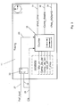
- Fig. 2 is basically self-explanatory with the help of the abbreviations used and (English) words, and the same also applies to the following figures. Consequently, only a few of the illustrated elements are discussed below. Additional conditions can be deduced from the figures.
- Fig. 2 basically explains the function of a programmable logic device used as an actuator of a control loop for controlling a 2-phase step motor.
- this actuator contains in particular a timing block 11, pulse-width modulators (PWM) 12 for the respective phases A and B, phase pattern generators 13 for phase A and B and short-circuit detectors 14 for phases A and B.
- PWM pulse-width modulators
- phase pattern generators 13 for phase A and B
- short-circuit detectors 14 for phases A and B.
- the driving signals 23 for the motor windings of the step motor are finally provided by the respective phase pattern generator 13.
- the respective actual phase signal of the phase 1 or 2 and A or B is first input via lines 15 in the respective phase pattern generator 13.
- modulation signals from the respective pulse-width modulators 12 are also input via lines 16 in the respective phase pattern generator 13.
- the pulse-width modulators 12 are located in a respective control loop and receive signals from the feedback elements 9A and 9B via lines 17.
- the pulse-width modulators 12 are also connected to the timing block 11 via lines 24, which controls them with its time signals and thus the pulse-width modulation decidedly influences and predetermines the respective requirements, conditions and functions of the respective step motor.
- short-circuit detectors 14 are linked together by a short-circuit conductor 19, which are summarized to one line 25 via a junction 26, and short-circuit detectors 14 are connected together via a line 20. They are also connected with the timing block 11 via a line 21. They are arranged via lines 22 on the input side in the short-circuit branches 10A and 10B.
- the timing block 11 comprises a counter 18 for its time signal, which can be programmed for the respective application according to the invention by the parameter constants input in the timing block 11, abbreviated now as "Min_on”, “Comp_dis_del”, “Comp_dis_len”, “Min_off” and “f_chop", but being the same constants as mentioned before with their whole names.
- the counter 18 is directly feeded with a clock signal "clk" via the line 29.
- a reference-load signal "Ref_load” is conducted in the Counter 18 via the line 27 and via a D-flip flop 33 (the D-input of the D-flip flop 33), whereby the clock signal "clk” is transmitted to a clear- or preset-input of the D-flip flop 33 via line 34 and the output-signal of the flip flop 33 is conducted from the output Q via a line 40 to an input of the counter 18.
- the output signals of the timing block 11 are the output signals of the Counter 18 and these are a short circuit time signal "shcct_time” on line 21, the Compensation disable signal “Comp_disable” on line 30, which compensates the idle time by using the Compensation disable delay constant “Comp_dis_del(-cnt)” and the Compensation disable length constant “Comp_dis_len(-cnt)", and a chopped clock signal (syncronized) "chop_clk(sync)" on line 24.
- Fig. 2 The further conducting of these output signals can be seen from and has been explained with Fig. 2.
- FIGS. 4 through 6 show a pulse-width modulator 12, a phase model generator 13 and a short-circuit detector 14 in greater detail and they are, as mentioned, self-explanatory for further details, if or as far as not expressively explained in the following.
- the Figure 4 shows a pulse-width modulator "PWM” 12 which generates the pulses "PWM_1/2" or signals for phases A and B for an input in the Pattern generator Phase A/B 13 via lines 16.
- the pulse-width modulators for Phases A and B are built equal. They are essentially consisting of a RS-flip flop (Set-reset flip flop) in the box 12.
- the RS-flip flop receives in its input S via line 24 the "Chop_clk(sync)" signal from the counter 18, in its clear- or preset-input C via line 29 a clock signal “clk” and in its input R signals "Curr_sens 1 ⁇ 2" from the feedback elements 9A and 9B via lines 17.
- the flip flop has an output Q.
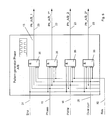
- the Figure 5 shows a Pattern generator Phase A/B 13, comprising four NAND-elements 35 with the phase signals "Ph_A/B_1", “Ph_A/B_1*”,”Ph_A/B_2”and”Ph_A/B_2*” as their output-signals for controlling the 2-phase step motor via lines 23.
- the input-signals for the four NAND-elements 35 are the enable signal "Ena” via line 31, a phase signal via line 15, the output-signal "PWM” from a pulse-width modulator 12 via line 16, an over current signal “Over curr” via line 25 and a reset signal “Res” via line 32, which can also seen from Figure 2.
- the Figure 6 shows a short-cut detector14, comprising an AND-element 36, a filter 37 and two RS-flip flops 38, 39 (with inputs S and R and outputs Q).
- the output-signal is a "Over_curr_1/2"-signal on a line 19.
- the short-cut detector 14 receives a short-cut signal "Shcct 1 ⁇ 2" via line 22, enable signals "Ena” via line 31 and a short-cut time signal "Shcct_time” via line 29 (resp. via line 20).
Landscapes
- Engineering & Computer Science (AREA)
- Power Engineering (AREA)
- Control Of Stepping Motors (AREA)
Abstract
Description
Claims (10)
- Device for producing an alternating current with a direct current source in at least one inductive load, in particular for driving a step motor, preferably in microsteps, characterized by a control loop and an actuator for the control loop, which contains a device for a complex programmable logic (CPLD; complex programmable logic device).
- Device for controlling the current in at least one inductive load, preferably for a device according to Claim 1, characterized by a control loop and an actuator, which can be parameterized by a use of a (universal) logic description by means of parameter constants.
- Device according to Claim 1 or 2, characterized by a device for pulse-width modulation (PWM) (12) of a control signal.
- Device according to Claim 2 and 3, characterized by a parameter constant (f_chop_cnt) for setting the basic frequency of the pulse-duration modulation.
- Device according to Claim 2 and 3, characterized by a parameter constant (Min_on_cnt) for setting the minimal on-period.
- Device according to Claim 2 and 3, characterized by a parameter constant (Min_off_cnt) for setting the minimal total break period.
- Device according to Claim 2 and 3, characterized by a parameter constant (Comp_dis_del_cnt) for setting the delay of the idle time in the control loop.
- Device according to Claim 2 and 3, characterized by a parameter constant (Comp_dis_len_cnt) for setting the length (duration) of the idle time in the control loop.
- Device according to one of the preceding claims, characterized by an H-bridge driver (5A, 5B) with at least one H-bridge (6A, 6B).
- Device according to one of the Claims 1 through 8, characterized by discreet transistors with a corresponding driver.
Priority Applications (1)
| Application Number | Priority Date | Filing Date | Title |
|---|---|---|---|
| EP02017041A EP1282223A3 (en) | 2001-08-04 | 2002-07-27 | Device for producing or controlling an alternating current in at least one inductive load |
Applications Claiming Priority (5)
| Application Number | Priority Date | Filing Date | Title |
|---|---|---|---|
| DE10138502 | 2001-08-04 | ||
| DE10138502 | 2001-08-04 | ||
| EP02005962 | 2002-03-15 | ||
| EP02005962A EP1282222A3 (en) | 2001-08-04 | 2002-03-15 | Device for producing or controlling an alternating current in at least one inductive load |
| EP02017041A EP1282223A3 (en) | 2001-08-04 | 2002-07-27 | Device for producing or controlling an alternating current in at least one inductive load |
Publications (2)
| Publication Number | Publication Date |
|---|---|
| EP1282223A2 true EP1282223A2 (en) | 2003-02-05 |
| EP1282223A3 EP1282223A3 (en) | 2005-01-12 |
Family
ID=27214545
Family Applications (1)
| Application Number | Title | Priority Date | Filing Date |
|---|---|---|---|
| EP02017041A Withdrawn EP1282223A3 (en) | 2001-08-04 | 2002-07-27 | Device for producing or controlling an alternating current in at least one inductive load |
Country Status (1)
| Country | Link |
|---|---|
| EP (1) | EP1282223A3 (en) |
Family Cites Families (1)
| Publication number | Priority date | Publication date | Assignee | Title |
|---|---|---|---|---|
| US6198241B1 (en) * | 1999-07-07 | 2001-03-06 | Westinghouse Air Brake Company | Motor protection for a powered door system |
-
2002
- 2002-07-27 EP EP02017041A patent/EP1282223A3/en not_active Withdrawn
Also Published As
| Publication number | Publication date |
|---|---|
| EP1282223A3 (en) | 2005-01-12 |
Similar Documents
| Publication | Publication Date | Title |
|---|---|---|
| US5311548A (en) | Digital control electronic having a pulse width modulated (PWM)-output signal for the control of electric control elements of a hydraulic system | |
| US4710686A (en) | Method and apparatus for control of current in a motor winding | |
| US6055960A (en) | Electronic throttle valve control apparatus | |
| US4958269A (en) | Current control for microprocessor motor drive | |
| JP5129908B2 (en) | Electric motor with two-mode power supply switching | |
| EP1030437A3 (en) | Method and apparatus for controlling a servo motor using a stepper motor controller integrated circuit | |
| GB2248981A (en) | Electric power generating system with active damping | |
| US7728540B2 (en) | Motor driving circuit | |
| US4140955A (en) | Stepping motor drive method and apparatus | |
| US6727674B2 (en) | Device for producing or controlling an alternating current in at least one inductive load | |
| US5999396A (en) | Circuit for driving a contactor | |
| EP1282223A2 (en) | Device for producing or controlling an alternating current in at least one inductive load | |
| EP0273506B1 (en) | Two lead bidirectional stepping motor control | |
| US6867645B1 (en) | Method and apparatus for providing pulse width modulation | |
| US5590237A (en) | Apparatus and method for controlling the rotation speed of electric motors | |
| JP2863449B2 (en) | Control method of DC motor by pulse width modulation signal | |
| JPH04229099A (en) | Controller for stepping motor | |
| ATE207671T1 (en) | FREQUENCY CONVERTER FOR OPERATING AN ASYNCHRONOUS THREE-PHASE MOTOR | |
| US6552516B2 (en) | Regulator system for controlling output voltage and method of controlling the same | |
| JPH11159652A (en) | Control device and control circuit for solenoid proportional control valve | |
| JP3131157B2 (en) | Drive circuit for brushless DC motor | |
| JP2924299B2 (en) | Drive device for brushless motor | |
| CA2159230C (en) | Noise reduction in a switched reluctance motor by current profile manipulation | |
| KR960009037Y1 (en) | Current control device of brushless motor | |
| JPS605361Y2 (en) | Pulse width modulation controller |
Legal Events
| Date | Code | Title | Description |
|---|---|---|---|
| PUAI | Public reference made under article 153(3) epc to a published international application that has entered the european phase |
Free format text: ORIGINAL CODE: 0009012 |
|
| AK | Designated contracting states |
Designated state(s): AT BE BG CH CY CZ DE DK EE ES FI FR GB GR IE IT LI LU MC NL PT SE SK TR |
|
| AX | Request for extension of the european patent |
Extension state: AL LT LV MK RO SI |
|
| RAP1 | Party data changed (applicant data changed or rights of an application transferred) |
Owner name: EASTMAN KODAK COMPANY |
|
| PUAL | Search report despatched |
Free format text: ORIGINAL CODE: 0009013 |
|
| AK | Designated contracting states |
Kind code of ref document: A3 Designated state(s): AT BE BG CH CY CZ DE DK EE ES FI FR GB GR IE IT LI LU MC NL PT SE SK TR |
|
| AX | Request for extension of the european patent |
Extension state: AL LT LV MK RO SI |
|
| 17P | Request for examination filed |
Effective date: 20050604 |
|
| AKX | Designation fees paid |
Designated state(s): AT BE BG CH CY CZ DE DK EE ES FI FR GB GR IE IT LI LU MC NL PT SE SK TR |
|
| 17Q | First examination report despatched |
Effective date: 20101007 |
|
| STAA | Information on the status of an ep patent application or granted ep patent |
Free format text: STATUS: THE APPLICATION IS DEEMED TO BE WITHDRAWN |
|
| 18D | Application deemed to be withdrawn |
Effective date: 20110218 |