EP1282149A2 - Deflection york and CRT device using the deflection york - Google Patents
Deflection york and CRT device using the deflection york Download PDFInfo
- Publication number
- EP1282149A2 EP1282149A2 EP02255383A EP02255383A EP1282149A2 EP 1282149 A2 EP1282149 A2 EP 1282149A2 EP 02255383 A EP02255383 A EP 02255383A EP 02255383 A EP02255383 A EP 02255383A EP 1282149 A2 EP1282149 A2 EP 1282149A2
- Authority
- EP
- European Patent Office
- Prior art keywords
- ferrite core
- deflection yoke
- glass bulb
- deflection
- deflection coil
- Prior art date
- Legal status (The legal status is an assumption and is not a legal conclusion. Google has not performed a legal analysis and makes no representation as to the accuracy of the status listed.)
- Granted
Links
Images





Classifications
-
- H—ELECTRICITY
- H01—ELECTRIC ELEMENTS
- H01J—ELECTRIC DISCHARGE TUBES OR DISCHARGE LAMPS
- H01J29/00—Details of cathode-ray tubes or of electron-beam tubes of the types covered by group H01J31/00
- H01J29/46—Arrangements of electrodes and associated parts for generating or controlling the ray or beam, e.g. electron-optical arrangement
- H01J29/82—Mounting, supporting, spacing, or insulating electron-optical or ion-optical arrangements
- H01J29/823—Mounting, supporting, spacing, or insulating electron-optical or ion-optical arrangements around the neck of the tube
- H01J29/826—Deflection arrangements
-
- H—ELECTRICITY
- H01—ELECTRIC ELEMENTS
- H01J—ELECTRIC DISCHARGE TUBES OR DISCHARGE LAMPS
- H01J29/00—Details of cathode-ray tubes or of electron-beam tubes of the types covered by group H01J31/00
- H01J29/46—Arrangements of electrodes and associated parts for generating or controlling the ray or beam, e.g. electron-optical arrangement
- H01J29/70—Arrangements for deflecting ray or beam
- H01J29/72—Arrangements for deflecting ray or beam along one straight line or along two perpendicular straight lines
- H01J29/76—Deflecting by magnetic fields only
-
- H—ELECTRICITY
- H01—ELECTRIC ELEMENTS
- H01J—ELECTRIC DISCHARGE TUBES OR DISCHARGE LAMPS
- H01J2229/00—Details of cathode ray tubes or electron beam tubes
- H01J2229/70—Electron beam control outside the vessel
- H01J2229/703—Electron beam control outside the vessel by magnetic fields
- H01J2229/7031—Cores for field producing elements, e.g. ferrite
Definitions
- the present invention relates to a deflection yoke and a cathode ray tube (CRT) device using the deflection yoke.
- FIGs. 1A, 1B, 1C, and 1D show, as one example, a color CRT device 100 resulted from such an attempt.
- the CRT device 100 has a 4:3 aspect ratio, a deflection angle of 100°, and a diagonal size of 19 inches.
- FIG. 1A is a schematic side view showing the color CRT device 100.
- the color CRT device 100 is composed of a CRT 102 and a deflection yoke 104.
- the CRT 102 includes a glass bulb 112 composed of: a glass panel 106 having a rectangular front face; a glass funnel 108; and a cylindrical glass neck 110 that are joined together in the stated order.
- a glass bulb 112 composed of: a glass panel 106 having a rectangular front face; a glass funnel 108; and a cylindrical glass neck 110 that are joined together in the stated order.
- Formed inside the panel 106 is a phosphor screen (not illustrated), and installed inside the neck 110 is an in-line type electron gun (not illustrated).
- the in-line type electron gun is composed of three electron guns respectively corresponding to B (blue), G (green), and R (red) arranged in a horizontal direction (X axis direction) in the stated order when seen from the side of the panel 106.
- the deflection yoke 104 is mounted along the outer surface of the glass bulb 112 in a manner to cover the boundary between the neck 110 and the funnel 108. That is, the deflection yoke 104 is mounted on the glass bulb 112 to cover a particular part.
- the outer surface of the glass bulb 112 has such a shape that cross sections taken along lines perpendicular to the tube axis (Z axis) of the CRT gradually change from circular to substantially rectangular as the section lines shift closer from the neck 110 to the panel 106.
- the ouster surface of the glass bulb where the deflection yoke is mounted is referred to as a "yoke-mounting part".
- the in-line type electron gun emits electron beams along the tube axis (Z axis) direction of the CRT 102.
- the electron beams are then deflected by the action of deflection magnetic field that is generated inside the deflection yoke 104 so as to accomplish scanning over the phosphor screen provided inside the panel 106.
- FIGs. 1B, 1C, and 1D are sectional views showing the deflection yoke 104 taken along the lines K-K, L-L, and M-M in FIG. 1A, respectively.
- the distances from the front face of the panel to the section lines K-K, L-L, and M-M in the axial direction (Z axis direction) are 56.9[mm], 31.9[mm], and 21.9[mm], respectively.
- the cross sections of the deflection yoke 104 change from circular to substantially rectangular as the section lines shift closer from the neck 110 to the panel 106, so that the deflection yoke 104 conforms to the outer shape of the yoke-mounting part of the glass bulb 112.
- the deflection yoke 104 is composed of: a funnel-shaped plastic separator 114 having a part of which cross section is substantially rectangular conforming to the outer shape of the yoke-mounting part of the glass bulb 112; a horizontal deflection coil 116 deposed along the inner surface of the separator 114; a vertical deflection coil 118 disposed along the outer surface of the separator 114; and a ferrite core 120 disposed externally to the vertical deflection coil 118 and having a part of which cross section is substantially rectangular.
- a conventionally common deflection yoke (not illustrated) is normally composed of a substantially conical separator, a horizontal deflection coil disposed along the inner surface of the separator, a vertical deflection coil disposed along the outer surface of the separator, and a substantially conical ferrite core disposed externally to the vertical deflection coil. Due to its shape, such a conventionally common deflection yoke inevitably has gaps of a considerable size formed between the horizontal deflection coil and the outer surface of the glass bulb.
- the deflection yoke 104 has the above-described construction. With this construction, it is intended to position the horizontal deflection coil 116 as close as possible to the outer surface of the glass bulb 112, so that the horizontal deflection coil 116 is positioned as close as possible to the path area of electron beams. This arrangement improves deflection efficiency and consequently reduces power consumption.
- the vertical deflection coil 118 is also positioned closer to the path area of electron beams than in a conventionally common deflection yoke. This arrangement also contributes to power consumption reduction. Yet, the horizontal deflection coil 116 consumes much greater power than vertical deflection coil 118 does. Thus, the advantageous effect of the deflection yoke 104 is achieved primary by the horizontal deflection coil 116 being arranged close to the glass bulb 112.
- the deflection yoke 104 has achieved improved deflection efficiency and, as a consequence, lower power consumption.
- the color CRT devices 100 composed of the deflection yoke 104 involve a problem that the convergence performance fluctuates to a greater extent than CRT devices composed of such a conventionally common deflection yoke as above.
- a first object of the present invention is to provide a deflection yoke capable of reducing power consumption without sacrifice of convergence performance as much as possible.
- a second object of the present invention is to provide a CRT device composed of a deflection yoke achieving the first object.
- FIG. 2 is a schematic view showing a color CRT device 10 according to this embodiment.
- the color CRT device 10 has a 4:3 aspect ratio, a deflection angle of 100°, and a diagonal size of 19 inches.
- the color CRT device 10 includes a glass bulb 20 that is composed of: a glass panel 14 having a substantially rectangular display 12 at the front; a glass funnel 16 joined to the panel 14; and a cylindrical glass neck 18 joined to the funnel 16.
- the funnel 16 literally has a funnel shape, and the tube end of the funnel shape is circular conforming to the shape of the neck 18 joined thereto.
- the flare part of the funnel shape is substantially in a shape of pyramid.
- a deflection yoke 24 Mounted around a yoke-mounting part 22 of the glass bulb 20 is a deflection yoke 24. That is, the deflection yoke 24 is disposed around the outer surface of the glass bulb 20 in a manner to cover the boundary between the neck 18 and the funnel 16.
- a phosphor screen 26 composed of a three-color phosphor layer that is composed of phosphors each emittingblue, green, or red light and are arranged in dots or stripes.
- a shadow mask 28 having a plurality of apertures for electron beams to pass through.
- an in-line type electron gun 32 Disposed within the neck 18 is an in-line type electron gun 32 that emits three electron beams 30.
- the in-line type electron gun is composed of three electron guns that correspond to B (blue), G (green), and R (red), respectively and that are horizontally arranged in the stated order from left to right when seen from the panel 14.
- the electron beams 30 are deflected in the horizontal and vertical directions by virtue of horizontal and vertical deflection magnetic fields that are generated by the deflection yoke 24, and pass through the apertures of the shadow mask 28 to be scanned horizontally and vertically over the phosphor screen 26. As a result, visible color images are produced on the display 12.
- the glass bulb 20 that includes the electron gun 32 and the other components described above is hereinafter referred to as a CRT 34. That is, the color CRT device 10 is composed of the CRT 34 and the deflection yoke 24.
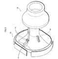
- FIG. 3 is an oblique view showing components of the deflection yoke 24, namely a separator 36 and a ferrite core 38.
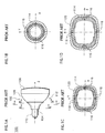
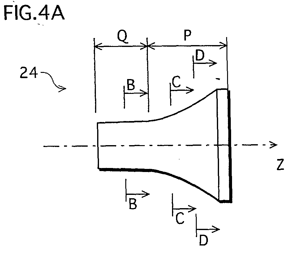
- FIG. 4A is a side view of the deflection yoke 24.
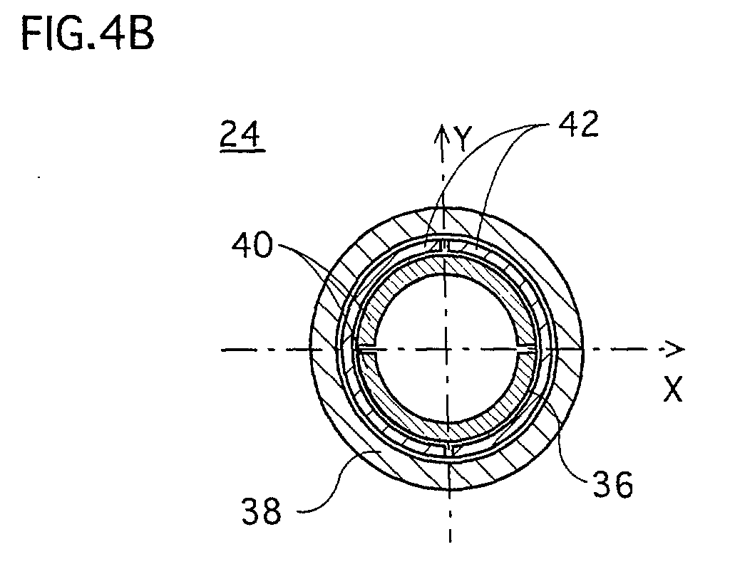
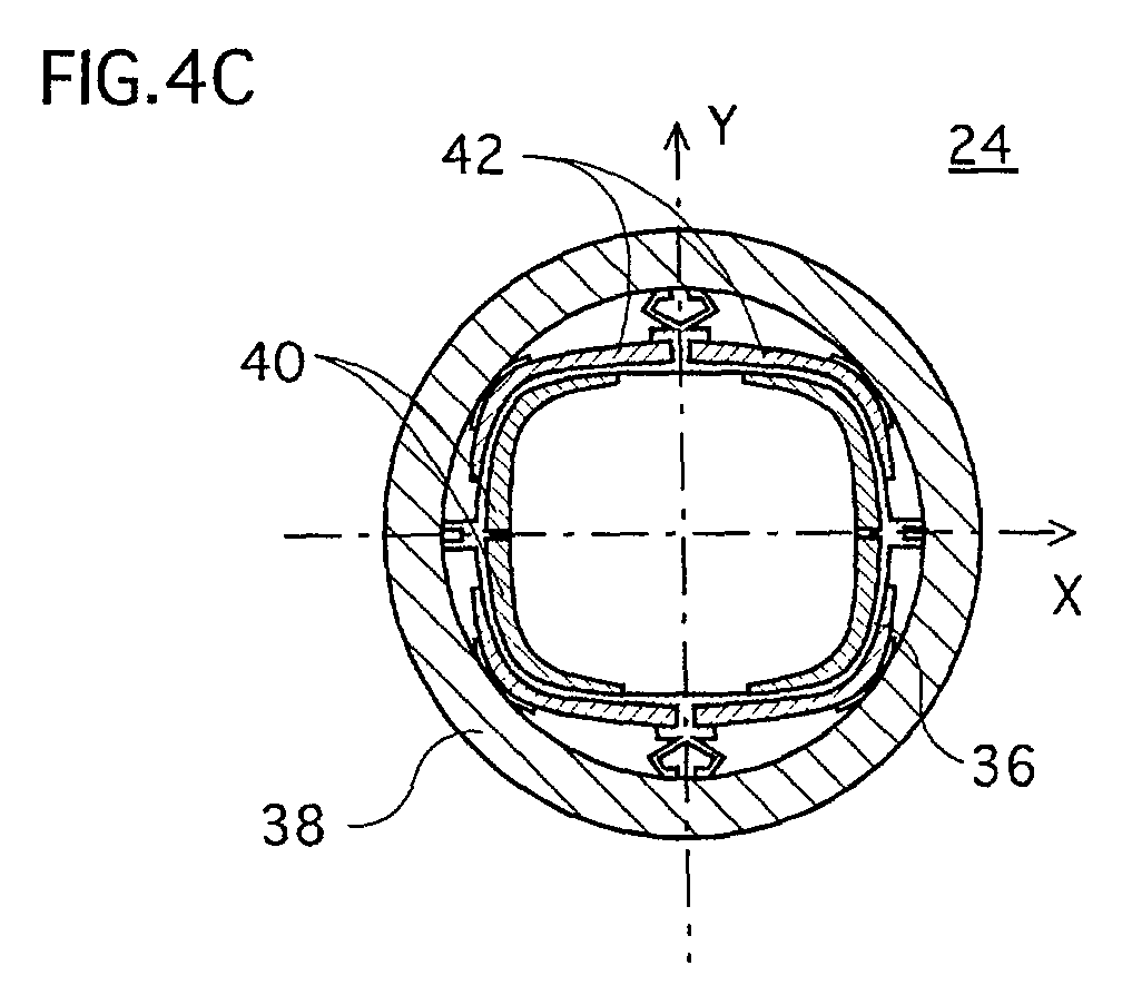
- FIGs. 4B-4D are sectional views showing the deflection yoke 24 taken along the lines B-B, C-C, and D-D shown in FIG. 4A, respectively.
- the distances from the front face of the panel 14 to the section lines B-B, C-C, and D-D in the axial direction (Z axis direction) are 56.9[mm], 31.9[mm], and 21.9[mm], respectively.
- the shape of the separator 36 gradually changes in cross section from circular at the part closer to the neck 18 of the CRT 34 to substantially rectangular at the part closer to the panel 14. That is, the separator 36 has a funnel shape conforming to the shape of the yoke-mounting part 22 of the glass bulb 20.
- the ferrite core 38 is always circular in cross section taking along any of the section lines. Yet, the diameter of the circular cross section is smaller as the section line is closer to the neck 18. As shown in FIG.
- the part P where the separator 36 is non-circular in the inner periphery of the cross section is referred to as a non-circular part
- the part Q where the separator 36 is circular in the inner periphery of the cross section is referred to as a circular part.
- FIG. 5 is an enlarged view of FIG. 4C.
- the separator 36 having the non-circular part is an insulating frame that insulates a horizontal deflection coil 40 and a vertical deflection coil 42.
- the separator 36 is made of a plastic material (electric non-conductance resin).
- the horizontal deflection coil 40 is composed of a pair of coil segments that are wound into a so-called saddle-shape and that are arranged inside the separator 36 symmetrically to the X axis (major axis) of the separator.
- the horizontal deflection coil 40 is disposed along the inner surface of the separator 36. That is, when the deflection yoke 24 is mounted to the glass bulb 20, the horizontal deflection coil 40 is located along the outer surface of the glass bulb 20 at the yoke-mounting part 22.
- the vertical deflection coil 42 is composed of a pair of coil segments that are wound into a saddle-shape and that are arranged outside the separator 36 symmetrically to the Y axis (minor axis) of the separator. From a macroscopic viewpoint, the horizontal deflection coil 40 and the vertical deflection coil 42 substantially define a rectangle in cross section so that both the coils conform to the shape of the separator 36.
- the ferrite core 38 is mounted in a manner to cover the separator 36, the horizontal deflection coil 40, and the vertical deflection coil 42.
- the ferrite core 38 has a funnel shape, and is circular in cross section.
- the deflection yoke 24 has the non-circular part P (see FIG. 4A) where the separator 36, the horizontal deflection coil 40, and the vertical deflection coil 42 are non-circular in cross section, thereby conforming to the shape of the yoke-mounting part 22 of the glass bulb 20.
- the horizontal deflection coil 40 and the vertical deflection coil 42 are closer to the path area of the electron beams 30 in comparison with a conventionally common deflection yoke composed of a substantially conical separator and a substantially conical ferrite core. As a consequence, power required to deflect the electron beams 30 (i.e., deflection power) is reduced.
- the deflection yoke 24 according to the embodiment of the present invention has the construction that, in the non-circular part P, the ferrite core 38 is farther away from the path area of the electron beams 30 in comparison with the deflection yoke 104 described with reference to FIGs. 1A-1D. For this reason, there was a concern that the deflection yoke 24 would require greater deflection power than the deflection yoke 104 did.
- computer simulations performed by the inventors of the present invention has made it clear, although the details of the simulations are omitted here, that the important factor to reduce deflection power lies not in the ferrite core but in the horizontal deflection coil and the vertical deflection coil (especially, the horizontal deflection coil).
- the deflection yoke 24 according to this embodiment of the present invention sufficiently realizes the effect to reduce deflection power.
- the tests were conducted on the deflection yoke 24 according to the embodiment of the present invention and the deflection yoke 104 according to the prior art.
- the electron beams 30 were deflected to a corner of the respective display and various measurements were made, and deflection power of each deflection yoke was calculated from the respective measurements.
- LH is an inductance of the horizontal deflection coil
- LV is an inductance of the vertical deflection coil
- RH is a resistance of the horizontal deflection coil
- RV is a resistance of the vertical deflection coil
- IH is a current passing through the horizontal deflection coil
- IV is a current passing through the vertical deflection coil. Note that all these values are actually measured values.
- PH is a deflection power required by the horizontal deflection coil
- the inventors of the present invention conducted tests to confirm that the deflection yoke 24 according to the present embodiment is better than the deflection yoke 104 in the convergence performance.
- the deflection yoke 24 is also referred to as a "rectangular coil-circular core type deflection yoke”
- the deflection yoke 104 is also referred to as a "rectangular coil-rectangular core type deflection yoke.
- the inventors of the present invention conducted measurements on the rectangular coil-circular core type deflection yoke 24 and the rectangular coil-rectangular core type deflection yoke 104 under the standard of EIAJ (Electronic Industries Association of Japan) to obtain "Xh” and "Xhs", the indices showing the state of convergence.
- the measurements were also conducted on the conventionally common deflection yoke mentioned in the "Description of the Related Art", i.e.
- a deflection yoke composed of a substantially conical separator, a horizontal deflection coil mounted along the inner surface of the separator, a vertical deflection coil mounted along the outer surface of the separator, and a substantially conical ferrite core disposed externally to the vertical deflection coil (hereinafter such a conventionally common deflection yoke is also referred to as "circular coil-circular core type deflection yoke).
- the rectangular coil-circular core type deflection yokes 24 according to the present embodiment exhibited the convergence performance of which variations (3 ⁇ ) were smaller than the variations of the rectangular coil-rectangular core type deflection yokes 104, and almost equal to the variations of the circular coil-circular core type deflection yokes.
- Factors contributing the above differences in the variations of the convergence performance may be ascribable to degrees of dimensional accuracy of each ferrite core, i.e., dimensional deviation of each ferrite core from the designed dimensions.
- ferrite cores are manufactured by press-molding magnetic powder into a metal mold, followed by sintering the press-molded body. At the time of sintering, the press-molded body inevitably undergoes volume contraction, which results in dimensional variations.
- the internal diameter of the ferrite core is especially influential in determining the convergence performance. This is because distribution of magnetic flux that the deflection coil generates varies depending on the internal shape of the ferrite core.
- the dimensional accuracy is such that the internal diameter of the ferrite core is held to vary within ⁇ 1% from the designed value.
- the substantiallypyramid-shaped ferrite core used in the deflection yoke 104 according to the prior art the dimensional accuracy is such that the internal rectangle varies within ⁇ 2.5% in the length of the major side, ⁇ 1.6% in the length of the minor side, and ⁇ 3.3% in the diagonal length.
- the difference in the dimensional accuracy among each type of ferrite cores may be ascribable to the uniformity in the ferrite core thickness and the axial symmetry to the tube axis.
- the convergence performance is expected to improve.
- the deflection yoke 24 according to the present invention having the substantially conical ferrite core 38 has the following advantage over the conventional deflection yoke 104 having the substantially pyramid-shaped ferrite core 120. That is, the substantially conical ferrite core has a smooth internal shape without corners, so that the internal surface maybe finishedwith grinding. On the contrary, such grinding is not possibly applied to the generally pyramid-shaped ferrite core, so that there is no choice but to use the ferrite core as sintered.
- metal-molded products are poor in the dimensional accuracy in comparison with ground products.
- the internal diameter of the ferrite core may be held to vary within ⁇ 0.2mm or so regardless of the size of the designed internal diameter.
- accuracy of the metal molding directly counts for the dimensional accuracy of the finished ferrite core, and thus the internal diameter of such a ferrite core varies from the designed internal diameter to the extent of ⁇ 1% or so.
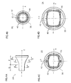
- FIG. 8A is a sectional view of a pyramid-shaped ferrite core taken along the line E-E shown in FIG. 8B.
- FIG. 8C is a sectional view of a conical ferrite core taken along the line F-F shown in FIG. 8D.
- the finished dimensions vary within the range of 0.79mm.
- the conic ferrite core shown in FIGs. 8C and 8D is better in the dimensional accuracy.
- a substantially conical ferrite core produced merely by sintering is still capable of improving the convergence performance in comparison with a substantially pyramid-shaped ferrite core. Yet, by grinding the internal surface of the ferrite core, the convergence performance is further improved. The grinding of the internal surface is done using a conventional grinding machine.
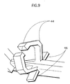
- FIG. 9 is an enlarged oblique view showing one of the resilient mechanisms 44.
- the resilient mechanisms 44 resiliently support the ferrite core, and prevent misalignment of the ferrite core 38 that possibly occurs at the time of assembling the deflection yoke 24. Since the misalignment of the ferrite core 38 is prevented, the deflection yoke exhibits stable magnetic field characteristics and convergence performance, whereby enabling to provide a color CRT device having good image quality.
- sandwiching mechanisms 46 in adjacent to each resilient mechanism 44. With the sandwiching mechanisms 46, it is possible to dispose the vertical deflection coil at any intended position. Thus, the deflection yoke exhibits stable magnetic field characteristics and convergence performance. Note that the horizontal deflection coil 40 is disposed along the inner surface of the separator 36.
- each holding mechanism 48 is in U-shape in cross section with an opening in the mold drawing direction as shown in FIG. 5.
- the holding mechanisms may have the similar shape and function to the resilient mechanisms 44.
- hollows 50 between the ferrite core 38 and the horizontal deflection coil 40 via the separator 36 there are provided hollows 52 between the ferrite core 38 and the vertical deflection coil 42.
- the separator 36, the horizontal deflection coil 40, and the vertical deflection coil 42 are all non-circular in cross sections, while the ferrite core 38 is circular in cross section.
- the deflection yoke 24 of the present invention secures the hollows that the conventional deflection yoke 104 shown in FIGs.1B-1D does not have.
- the hollows 50 and 52 serve to improve cooling effect of the horizontal deflection coil 40 and the vertical deflection coil 42.
- the horizontal deflection coil 40 and the vertical deflection coil 42 generate less heat in comparison with conventional deflection coils included in a deflection yoke having no such hollows, thus temperature rise in the entire deflection yoke 24 is suppressed.
- the diameter of the ferrite core 38 may be enlarged while the dimensions of the separator 36 are left unchanged, thereby enlarging the hollows 50 and 52. Being larger in diameter, however, the ferrite core 38 exhibits less effect on increasing magnetic flux density, which as a result requiring greater deflection power. In addition, if the diameter of the ferrite core 38 is larger without changing the dimensions of the other components, it is increasingly difficult to securely hold the ferrite core 38. As a consequence, the problem of misalignment is likely to arise . In view of the above, it is preferable to dispose the ferrite core 38 close to the horizontal deflection coil 40 and the vertical deflection coil 42. In other words, it is preferable that the inner diameter of the ferrite core 38 be as small as possible.
- the inner diameter of the ferrite core 38 at the non-circular part P be made to generally equal to the diagonal distance of the substantially rectangular cross section of the separator 36, or of the substantial rectangle defined by the horizontal deflection coil 40 and the vertical deflection coil 42.
- the inner diameter of the ferrite core 38 be made generally equal to the diagonal distance between the outermost corners of the vertical deflection coil 42.
- the vertical deflection coil 42 is provided with an adhesive member 54 such as an adhesive sheet along each corner of the substantial rectangle, which is in contact with the separator 36, so that the vertical deflection coil 42 is protected and fixed to the separator 36.
- FIGs. 11 and 12 show the dimensions of each part of respective ferrite cores and separators of the deflection yoke 24 according to the present invention and the deflection yoke 104 according to the prior art, respectively. The dimensions were measured in the cross sections shown in FIGs. 4B-4D and in FIGs. 1B-1D, respectively.
- the horizontal deflection coil and the vertical deflection coil were disposed along the inner and outer surface of each separator, respectively.
- the temperature of the horizontal deflection coil in the conventional deflection yoke 104 rose to 110°C
- the temperature of the horizontal deflection coil in the deflection yoke 24 of the present embodiment rose only to 103°C. That is to say, the deflection yoke 24 according to the present embodiment successfully reduces the temperature rise of the horizontal deflection coil by 7°C in comparison with that in the conventional deflection yoke 104.
- the reason for measuring the temperature of the horizontal deflection coil is because the horizontal deflection coil is where the temperature apt to rise most in the deflection yoke.
- the separator of the deflection yoke is made of a plastic material, such as PPE (polyphenylene ether) resin, and the long-term thermal deformation resistance of the resin is guaranteed at temperatures up to 110°C.
- PPE polyphenylene ether
- the separator is thermally deformed so that the insulation between the horizontal deflection coil and the vertical deflection coil may not be maintained.
- the deflection yoke 24 according to the present invention the above risk is eliminated, thereby improving thermal reliability of the deflection yoke.
- the horizontal deflection coil may be a similar one to the above horizontal deflection coil, i.e., a saddle-shaped horizontal deflection coil disposed along the inner surface of the ferrite core .
- the vertical deflection coil may be a toroidal coil that is wound around the ferrite core.
Landscapes
- Vessels, Lead-In Wires, Accessory Apparatuses For Cathode-Ray Tubes (AREA)
- Video Image Reproduction Devices For Color Tv Systems (AREA)
Abstract
Description
Claims (7)
- A deflection yoke mounted around a glass bulb of a CRT so as to cover a predetermined area of the glass bulb, the predetermined area being where an outer shape of the glass bulb smoothly goes from circular to substantially rectangular along a tube axis of the CRT, the deflection yoke comprising:a horizontal deflection coil disposed in a shape to fit with the outer shape of the glass bulb; anda funnel-shaped ferrite core disposed to surround the horizontal deflection coil, an inner shape of the ferrite core being circular throughout a length of the ferrite core.
- The deflection yoke of Claim 1, wherein
an inner surface of the ferrite core has been ground with a grinding machine. - The deflection yoke of Claim 1, further comprising:a funnel-shaped insulating frame disposed in a shape to fit with the outer shape of the predetermined area and to be covered with the ferrite core, wherein the horizontal deflection coil is held along an inner surface of the insulation frame so as to be electrically insulated from a vertical deflection coil that is disposed in a shape to fit with an outer shape of the insulating frame; anda resilient support member disposed in a gap between the insulating frame and the ferrite core, the resilient support member resiliently supporting the ferrite core against the insulating frame.
- The deflection yoke of Claim 3, wherein
the resilient support member is made of a flexible member and supports the ferrite core by a restoring force of the flexible member, and
the deflection yoke further includes a protecting member that restricts a flexible amount of the flexible member so as to protect the flexible member from being damaged. - The deflection yoke of Claim 1, further comprising:a funnel-shaped insulating frame disposed in a shape to fit with the outer shape of the predetermined area, and holding the horizontal deflection coil along an inner surface of the insulating frame;a vertical deflection coil disposed in a shape to fit with an outer shape of the insulating frame; anda sandwiching member for partly sandwiching the vertical deflection coil between the sandwiching member and the outer surface of the insulating frame.
- A deflection yoke mounted around a glass bulb of a CRT so as to cover a predetermined area of the glass bulb, the predetermined area being where an outer shape of the glass bulb smoothly goes from circular to substantially rectangular along a tube axis of the CRT, the deflection yoke comprising:a horizontal deflection coil disposed in a shape to fit with the outer shape of the glass bulb; anda funnel-shaped ferrite core disposed to surround the horizontal deflection coil, an inner surface of the ferrite core having been ground with a grinding machine.
- A CRT device comprising:a CRT having a glass bulb; anda deflection yoke of Claim 1, whereinthe deflection yoke is mounted around the glass bulb so as to cover a predetermined area of the glass bulb, the predetermined area being where an outer shape of the glass bulb smoothly goes from circular to substantially rectangular along a tube axis of the CRT.
Applications Claiming Priority (2)
| Application Number | Priority Date | Filing Date | Title |
|---|---|---|---|
| JP2001233240 | 2001-08-01 | ||
| JP2001233240 | 2001-08-01 |
Publications (3)
| Publication Number | Publication Date |
|---|---|
| EP1282149A2 true EP1282149A2 (en) | 2003-02-05 |
| EP1282149A3 EP1282149A3 (en) | 2003-03-12 |
| EP1282149B1 EP1282149B1 (en) | 2004-10-13 |
Family
ID=19065037
Family Applications (1)
| Application Number | Title | Priority Date | Filing Date |
|---|---|---|---|
| EP02255383A Expired - Lifetime EP1282149B1 (en) | 2001-08-01 | 2002-08-01 | Deflection yoke and CRT device using the deflection yoke |
Country Status (5)
| Country | Link |
|---|---|
| US (1) | US6903520B2 (en) |
| EP (1) | EP1282149B1 (en) |
| KR (1) | KR100872919B1 (en) |
| CN (1) | CN1251286C (en) |
| DE (1) | DE60201561T2 (en) |
Families Citing this family (1)
| Publication number | Priority date | Publication date | Assignee | Title |
|---|---|---|---|---|
| KR20040013916A (en) * | 2002-08-09 | 2004-02-14 | 삼성에스디아이 주식회사 | Deflection yoke for cathode ray tube |
Family Cites Families (13)
| Publication number | Priority date | Publication date | Assignee | Title |
|---|---|---|---|---|
| US2824267A (en) | 1953-11-02 | 1958-02-18 | Rca Corp | Deflection yoke for multi-beam cathode ray tube |
| US3075131A (en) * | 1957-05-27 | 1963-01-22 | Indiana General Corp | Deflection yoke core for cathode ray tubes |
| NL7302257A (en) * | 1973-02-19 | 1974-08-21 | ||
| JPH087781A (en) | 1994-06-23 | 1996-01-12 | Sony Corp | Deflection yoke core |
| JPH09180652A (en) * | 1995-12-27 | 1997-07-11 | Sony Corp | Deflection yoke |
| JP3737191B2 (en) | 1996-04-26 | 2006-01-18 | 株式会社東芝 | Cathode ray tube deflection yoke and cathode ray tube apparatus |
| JPH10172473A (en) * | 1996-12-12 | 1998-06-26 | Toshiba Corp | Deflection yoke device |
| KR19980051541A (en) * | 1996-12-23 | 1998-09-15 | 구자홍 | Deflection yoke for cathode ray tube |
| JP3403005B2 (en) | 1997-06-20 | 2003-05-06 | 株式会社東芝 | Cathode ray tube device |
| EP1102301A1 (en) | 1999-11-19 | 2001-05-23 | Lg Electronics Inc. | Ferrite core in deflection yoke for braun tube |
| US6559588B1 (en) * | 2000-06-16 | 2003-05-06 | Samsung Electro-Mechanics Co., Ltd. | Deflection yoke |
| CN1213456C (en) * | 2000-07-21 | 2005-08-03 | 东芝株式会社 | Deflection yoke and cathode ray tube device having same |
| EP1265265A3 (en) * | 2001-06-09 | 2002-12-18 | Lg Electronics Inc. | Deflection yoke in CRT |
-
2002
- 2002-07-29 US US10/207,941 patent/US6903520B2/en not_active Expired - Fee Related
- 2002-08-01 DE DE60201561T patent/DE60201561T2/en not_active Expired - Fee Related
- 2002-08-01 CN CNB021275785A patent/CN1251286C/en not_active Expired - Fee Related
- 2002-08-01 EP EP02255383A patent/EP1282149B1/en not_active Expired - Lifetime
- 2002-08-01 KR KR1020020045487A patent/KR100872919B1/en not_active Expired - Fee Related
Also Published As
| Publication number | Publication date |
|---|---|
| US6903520B2 (en) | 2005-06-07 |
| KR100872919B1 (en) | 2008-12-08 |
| EP1282149B1 (en) | 2004-10-13 |
| CN1251286C (en) | 2006-04-12 |
| EP1282149A3 (en) | 2003-03-12 |
| US20030025468A1 (en) | 2003-02-06 |
| DE60201561D1 (en) | 2004-11-18 |
| CN1400624A (en) | 2003-03-05 |
| KR20030013293A (en) | 2003-02-14 |
| DE60201561T2 (en) | 2005-02-24 |
Similar Documents
| Publication | Publication Date | Title |
|---|---|---|
| US6166484A (en) | Deflection yoke, cathode-ray tube device using the same and display device | |
| US6590327B2 (en) | Color cathode ray tube having flat outer face | |
| EP1282149B1 (en) | Deflection yoke and CRT device using the deflection yoke | |
| US5304891A (en) | Cathode-ray tube display device | |
| EP1102301A1 (en) | Ferrite core in deflection yoke for braun tube | |
| US6787977B2 (en) | Electron gun for cathode-ray tube and method for manufacturing the same | |
| US6914505B2 (en) | Deflection yoke and CRT device | |
| JP3927461B2 (en) | Deflection yoke and cathode ray tube apparatus using the deflection yoke | |
| US7157998B2 (en) | Ferrite core, deflection yoke, and color picture tube apparatus | |
| KR200202676Y1 (en) | Deflection yoke | |
| US6756726B2 (en) | Deflection yoke and cathode-ray tube apparatus with the same | |
| US6590329B2 (en) | Deflection yoke with a low power consumption | |
| KR100321818B1 (en) | Deflection yoke, and cathode ray tube apparatus and display apparatus using the same | |
| JP3932986B2 (en) | Color picture tube device | |
| EP1296349A2 (en) | Deflection yoke | |
| KR100295452B1 (en) | Deflection Yoke for Cathode-ray Tube | |
| US6563259B2 (en) | Deflection yoke of braun tube and method for fabricating auxiliary coil of deflection yoke | |
| JP2007042661A (en) | Deflection yoke and cathode ray tube apparatus using the deflection yoke | |
| US7312565B2 (en) | Color cathode ray tube apparatus | |
| EP1329935B1 (en) | Cathode ray tube | |
| US6822382B2 (en) | Deflection yoke | |
| KR100451946B1 (en) | Deflection yoke | |
| JP2004039583A (en) | Projection type cathode ray tube device | |
| JP2004247224A (en) | Deflection yoke and cathode ray tube device | |
| WO2003023812A1 (en) | Deflecting yoke and deflecting yoke-use core |
Legal Events
| Date | Code | Title | Description |
|---|---|---|---|
| PUAI | Public reference made under article 153(3) epc to a published international application that has entered the european phase |
Free format text: ORIGINAL CODE: 0009012 |
|
| PUAL | Search report despatched |
Free format text: ORIGINAL CODE: 0009013 |
|
| AK | Designated contracting states |
Designated state(s): AT BE BG CH CY CZ DE DK EE ES FI FR GB GR IE IT LI LU MC NL PT SE SK TR |
|
| AX | Request for extension of the european patent |
Extension state: AL LT LV MK RO SI |
|
| AK | Designated contracting states |
Designated state(s): AT BE BG CH CY CZ DE DK EE ES FI FR GB GR IE IT LI LU MC NL PT SE SK TR Kind code of ref document: A3 Designated state(s): AT BE BG CH CY CZ DE DK EE ES FI FR GB GR IE IT LI LU MC NL PT SE SK TR |
|
| AX | Request for extension of the european patent |
Extension state: AL LT LV MK RO SI |
|
| 17P | Request for examination filed |
Effective date: 20030624 |
|
| 17Q | First examination report despatched |
Effective date: 20030829 |
|
| AKX | Designation fees paid |
Designated state(s): DE FR GB IT NL |
|
| GRAP | Despatch of communication of intention to grant a patent |
Free format text: ORIGINAL CODE: EPIDOSNIGR1 |
|
| RTI1 | Title (correction) |
Free format text: DEFLECTION YOKE AND CRT DEVICE USING THE DEFLECTION YOKE |
|
| GRAS | Grant fee paid |
Free format text: ORIGINAL CODE: EPIDOSNIGR3 |
|
| GRAA | (expected) grant |
Free format text: ORIGINAL CODE: 0009210 |
|
| AK | Designated contracting states |
Kind code of ref document: B1 Designated state(s): DE FR GB IT NL |
|
| REG | Reference to a national code |
Ref country code: GB Ref legal event code: FG4D |
|
| REF | Corresponds to: |
Ref document number: 60201561 Country of ref document: DE Date of ref document: 20041118 Kind code of ref document: P |
|
| PLBE | No opposition filed within time limit |
Free format text: ORIGINAL CODE: 0009261 |
|
| STAA | Information on the status of an ep patent application or granted ep patent |
Free format text: STATUS: NO OPPOSITION FILED WITHIN TIME LIMIT |
|
| ET | Fr: translation filed | ||
| 26N | No opposition filed |
Effective date: 20050714 |
|
| PGFP | Annual fee paid to national office [announced via postgrant information from national office to epo] |
Ref country code: DE Payment date: 20080814 Year of fee payment: 7 Ref country code: NL Payment date: 20080815 Year of fee payment: 7 |
|
| PGFP | Annual fee paid to national office [announced via postgrant information from national office to epo] |
Ref country code: FR Payment date: 20080818 Year of fee payment: 7 Ref country code: IT Payment date: 20080828 Year of fee payment: 7 |
|
| PGFP | Annual fee paid to national office [announced via postgrant information from national office to epo] |
Ref country code: GB Payment date: 20080813 Year of fee payment: 7 |
|
| REG | Reference to a national code |
Ref country code: NL Ref legal event code: V1 Effective date: 20100301 |
|
| GBPC | Gb: european patent ceased through non-payment of renewal fee |
Effective date: 20090801 |
|
| REG | Reference to a national code |
Ref country code: FR Ref legal event code: ST Effective date: 20100430 |
|
| PG25 | Lapsed in a contracting state [announced via postgrant information from national office to epo] |
Ref country code: NL Free format text: LAPSE BECAUSE OF NON-PAYMENT OF DUE FEES Effective date: 20100301 Ref country code: DE Free format text: LAPSE BECAUSE OF NON-PAYMENT OF DUE FEES Effective date: 20100302 Ref country code: FR Free format text: LAPSE BECAUSE OF NON-PAYMENT OF DUE FEES Effective date: 20090831 |
|
| PG25 | Lapsed in a contracting state [announced via postgrant information from national office to epo] |
Ref country code: GB Free format text: LAPSE BECAUSE OF NON-PAYMENT OF DUE FEES Effective date: 20090801 |
|
| PG25 | Lapsed in a contracting state [announced via postgrant information from national office to epo] |
Ref country code: IT Free format text: LAPSE BECAUSE OF NON-PAYMENT OF DUE FEES Effective date: 20090801 |