EP1282114A1 - Data processing apparatus - Google Patents
Data processing apparatus Download PDFInfo
- Publication number
- EP1282114A1 EP1282114A1 EP02710340A EP02710340A EP1282114A1 EP 1282114 A1 EP1282114 A1 EP 1282114A1 EP 02710340 A EP02710340 A EP 02710340A EP 02710340 A EP02710340 A EP 02710340A EP 1282114 A1 EP1282114 A1 EP 1282114A1
- Authority
- EP
- European Patent Office
- Prior art keywords
- data
- tap
- prediction
- predetermined
- subject
- Prior art date
- Legal status (The legal status is an assumption and is not a legal conclusion. Google has not performed a legal analysis and makes no representation as to the accuracy of the status listed.)
- Withdrawn
Links
Images





Classifications
-
- G—PHYSICS
- G10—MUSICAL INSTRUMENTS; ACOUSTICS
- G10L—SPEECH ANALYSIS TECHNIQUES OR SPEECH SYNTHESIS; SPEECH RECOGNITION; SPEECH OR VOICE PROCESSING TECHNIQUES; SPEECH OR AUDIO CODING OR DECODING
- G10L19/00—Speech or audio signals analysis-synthesis techniques for redundancy reduction, e.g. in vocoders; Coding or decoding of speech or audio signals, using source filter models or psychoacoustic analysis
- G10L19/04—Speech or audio signals analysis-synthesis techniques for redundancy reduction, e.g. in vocoders; Coding or decoding of speech or audio signals, using source filter models or psychoacoustic analysis using predictive techniques
- G10L19/08—Determination or coding of the excitation function; Determination or coding of the long-term prediction parameters
- G10L19/12—Determination or coding of the excitation function; Determination or coding of the long-term prediction parameters the excitation function being a code excitation, e.g. in code excited linear prediction [CELP] vocoders
Definitions
- the present invention relates to a data processing apparatus. More particularly, the present invention relates to a data processing apparatus capable of decoding speech which is coded by, for example, a CELP (Code Excited Linear coding) method into high-quality speech.
- a CELP Code Excited Linear coding
- Figs. 1 and 2 show the configuration of an example of a conventional mobile phone.
- a transmission process of coding speech into a predetermined code by a CELP method and transmitting the codes, and a receiving process of receiving codes transmitted from other mobile phones and decoding the codes into speech are performed.
- Fig. 1 shows a transmission section for performing the transmission process
- Fig. 2 shows a receiving section for performing the receiving process.
- speech produced from a user is input to a microphone 1, whereby the speech is converted into an speech signal as an electrical signal, and the signal is supplied to an A/D (Analog/Digital) conversion section 2.
- the A/D conversion section 2 samples an analog speech signal from the microphone 1, for example, at a sampling frequency of 8 kHz, etc., so that the analog speech signal undergoes A/D conversion from an analog signal into a digital speech signal.
- the A/D conversion section 2 performs quantization of the signal with a predetermined number of bits and supplies the signal to an arithmetic unit 3 and an LPC (Linear Prediction Coefficient) analysis section 4.
- LPC Linear Prediction Coefficient
- the vector quantization section 5 stores a codebook in which a code vector having linear predictive coefficients as elements corresponds to codes, performs vector quantization on a feature vector ⁇ from the LPC analysis section 4 on the basis of the codebook, and supplies the codes (hereinafter referred to as an "A_code" as appropriate) obtained as a result of the vector quantization to a code determination section 15.
- the vector quantization section 5 supplies linear predictive coefficients ⁇ 1 ', ⁇ 2 ',..., ⁇ p ', which are elements forming a code vector ⁇ ' corresponding to the A_code, to a speech synthesis filter 6.
- IIR Infinite Impulse Response
- ⁇ e n ⁇ (..., e n-1 , e n , e n+1 ,...) are probability variables, which are uncorrelated with each other, in which the average value is 0 and the variance is a predetermined value ⁇ 2 .
- the speech signal s n can be determined by assuming the linear predictive coefficient ⁇ p to be a tap coefficient of the IIR filter and by assuming the residual signal e n to be an input signal of the IIR filter.
- the speech synthesis filter 6 assumes the linear predictive coefficient ⁇ p ' from the vector quantization section 5 to be a tap coefficient, assumes the residual signal e supplied from the arithmetic unit 14 to be an input signal, and computes equation (4) in order to determine an speech signal (synthesized speech data) ss.
- the synthesized speech signal output from the speech synthesis filter 6 does not become the same as the speech signal output from the A/D conversion section 2.
- the synthesized speech signal ss output from the speech synthesis filter 6 is supplied to the arithmetic unit 3.
- the arithmetic unit 3 subtracts an speech signal s output by the A/D conversion section 2 from the synthesized speech data ss from the speech synthesis filter 6 (subtracts the sample of the speech data s corresponding to that sample from each sample of the synthesized speech data ss), and supplies the subtracted value to a square-error computation section 7.
- the A/D conversion section 7 computes the sum of squares (sum of squares in units of subframes which form the frame in which LPC analysis is performed by the LPC analysis section 4) of the subtracted value from the arithmetic unit 3 and supplies the resulting square error to a least-square error determination section 8.
- the least-square error determination section 8 has stored therein an L code (L_code) as a code indicating a lag, a G code (G_code) as a code indicating a gain, and an I code (I_code) as a code indicating a codeword (excitation codebook) in such a manner as to correspond to the square error output from the square-error computation section 7, and outputs the L_code, the G code, and the L code corresponding to the square error output from the square-error computation section 7.
- the L code is supplied to an adaptive codebook storage section 9.
- the G code is supplied to a gain decoder 10.
- the I code is supplied to an excitation-codebook storage section 11. Furthermore, the L code, the G code, and the I code are also supplied to the code determination section 15.
- the adaptive codebook storage section 9 has stored therein an adaptive codebook in which, for example, a 7-bit L code corresponds to a predetermined delay time (long-term prediction lag).
- the adaptive codebook storage section 9 delays the residual signal e supplied from the arithmetic unit 14 by a delay time corresponding to the L code supplied from the least-square error determination section 8 and outputs the signal to an arithmetic unit 12. That is, the adaptive codebook storage section 9 is formed of, for example, memory, and delays the residual signal e from the arithmetic unit 14 by the amount of samples corresponding to the value indicated by the 7-bit record and outputs the signal to the arithmetic unit 12.
- the adaptive codebook storage section 9 delays the residual signal e by a time corresponding to the L code and outputs the signal, the output signal becomes a signal close to a period signal in which the delay time is a period.
- This signal becomes mainly a driving signal for generating synthesized speech of voiced sound in speech synthesis using linear predictive coefficients.
- a gain decoder 10 has stored therein a table in which the G code corresponds to predetermined gains ⁇ and ⁇ , and outputs gains ⁇ and ⁇ corresponding to the G code supplied from the least-square error determination section 8.
- the gains ⁇ and ⁇ are supplied to the arithmetic units 12 and 13, respectively.
- the gain ⁇ is what is commonly called a long-term filter status output gain
- the gain ⁇ is what is commonly called an excitation codebook gain.
- the excitation-codebook storage section 11 has stored therein an excitation codebook in which, for example, a 9-bit I code corresponds to a predetermined excitation signal, and outputs, to the arithmetic unit 13, the excitation signal which corresponds to the I code supplied from the least-square error determination section 8.
- the excitation signal stored in the excitation codebook is, for example, a signal close to white noise, and becomes mainly a driving signal for generating synthesized speech of unvoiced sound in the speech synthesis using linear predictive coefficients.
- the arithmetic unit 12 multiplies the output signal of the adaptive codebook storage section 9 with the gain ⁇ output from the gain decoder 10 and supplies the multiplied value 1 to the arithmetic unit 14.
- the arithmetic unit 13 multiplies the output signal of the excited codebook storage section 11 with the gain ⁇ output from the gain decoder 10 and supplies the multiplied value n to the arithmetic unit 14.
- the arithmetic unit 14 adds together the multiplied value 1 from the arithmetic unit 12 with the multiplied value n from the arithmetic unit 13, and supplies the added value as the residual signal e to the speech synthesis filter 6 and the adaptive codebook storage section 9.
- the residual signal e supplied from the arithmetic unit 14 is filtered by the IIR filter in which the linear predictive coefficient ⁇ p ' supplied from the vector quantization section 5 is a tap coefficient, and the resulting synthesized speech data is supplied to the arithmetic unit 3. Then, in the arithmetic unit 3 and the square-error computation section 7, processes similar to the above-described case are performed, and the resulting square error is supplied to the least-square error determination section 8.
- the least-square error determination section 8 determines whether or not the square error from the square-error computation section 7 has become a minimum (local minimum). Then, when the least-square error determination section 8 determines that the square error has not become a minimum, the least-square error determination section 8 outputs the L code, the G code, and the I code corresponding to the square error in the manner described above, and hereafter, the same processes are repeated.
- the least-square error determination section 8 determines that the square error has become a minimum
- the least-square error determination section 8 outputs the determination signal to the code determination section 15.
- the code determination section 15 sequentially latches the A code supplied from the vector quantization section 5 and sequentially latches the L code, the G code, and the I code supplied from the least-square error determination section 8.
- the code determination section 15 supplies the A code, the L code, the G code, and the I code, which are latched at this time, to the channel encoder 16.
- the channel encoder 16 multiplexes the A code, the L code, the G code, and the I code from the code determination section 15 and outputs them as code data. This code data is transmitted via a transmission path.
- the code data is coded data having the A code, the L code, the G code, and the I code, which are information used for decoding, in units of subframes.
- the A code, the L code, the G code, and the I code are determined for each subframe.
- the A code is sometimes determined for each frame.
- the same A code is used to decode the four subframes which form that frame.
- each of the four subframes which form that one frame can be regarded as having the same A code.
- the code data can be regarded as being formed as coded data having the A code, the L code, the G code, and the I code, which are information used for decoding, in units of subframes.
- [k] is assigned to each variable so that the variable is an array variable.
- This k represents the number of subframes, but in the specification, a description thereof is omitted where appropriate.
- the channel decoder 21 separates the L code, the G code, the I code, and the A code from the code data, and supplies each of them to an adaptive codebook storage section 22, a gain decoder 23, an excitation codebook storage section 24, and a filter coefficient decoder 25.
- the adaptive codebook storage section 22, the gain decoder 23, the excitation codebook storage section 24, and arithmetic units 26 to 28 are formed similarly to the adaptive codebook storage section 9, the gain decoder 10, the excited codebook storage section 11, and the arithmetic units 12 to 14 of Fig. 1, respectively.
- the L code, the G code, and the I code are decoded into the residual signal e.
- This residual signal e is provided as an input signal to a speech synthesis filter 29.
- the filter coefficient decoder 25 has stored therein the same codebook as that stored in the vector quantization section 5 of Fig. 1, so that the A code is decoded into a linear predictive coefficient ⁇ p ' and this is supplied to the speech synthesis filter 29.
- the speech synthesis filter 29 is formed similarly to the speech synthesis filter 6 of Fig. 1.
- the speech synthesis filter 29 assumes the linear predictive coefficient ⁇ p ' from the filter coefficient decoder 25 to be a tap coefficient, assumes the residual signal e supplied from an arithmetic unit 28 to be an input signal, and computes equation (4), thereby generating synthesized speech data when the square error is determined to be a minimum in the least-square error determination section 8 of Fig. 1.
- This synthesized speech data is supplied to a D/A (Digital/Analog) conversion section 30.
- the D/A conversion section 30 subjects the synthesized speech data from the speech synthesis filter 29 to D/A conversion from a digital signal into an analog signal, and supplies the analog signal to a speaker 31, whereby the signal is output.
- linear predictive coefficients corresponding to the A codes arranged in that frame can be used to decode all four subframes which form the frame.
- interpolation is performed on each subframe by using the linear predictive coefficients corresponding to the A code of the adjacent frame, and the linear predictive coefficients obtained as a result of the interpolation can be used to decode each subframe.
- the codes are decoded into a residual signal and linear predictive coefficients.
- the decoded residual signal and linear predictive coefficients contain errors such as quantization errors, these do not match the residual signal and the linear predictive coefficients obtained by performing LPC analysis on speech.
- the synthesized speech signal output from the speech synthesis filter 29 of the receiving section becomes deteriorated sound quality in which distortion is contained.
- the present invention has been made in view of such circumstances, and aims to obtain high-quality synthesized speech, etc.
- a first data processing apparatus of the present invention comprises: tap generation means for generating a tap used for a predetermined process by extracting the decoded data in a predetermined positional relationship with subject data of interest within the decoded data such that the coded data is decoded and by extracting the decoding information in predetermined units according to the position of the subject data in the predetermined units; and processing means for performing a predetermined process by using the tap.
- a first data processing method of the present invention comprises: a tap generation step of generating a tap used for a predetermined process by extracting the decoded data in a predetermined positional relationship with subject data of interest within the decoded data such that the coded data is decoded and by extracting the decoding information in predetermined units according to the position of the subject data in the predetermined units; and a processing step of performing a predetermined process by using the tap.
- a first program comprises: a tap generation step of generating a tap used for a predetermined process by extracting the decoded data in a predetermined positional relationship with subject data of interest within the decoded data such that the coded data is decoded and by extracting the decoding information in predetermined units according to the position of the subject data in the predetermined units; and a processing step of performing a predetermined process by using the tap.
- a first recording medium having recorded thereon a program comprises: a tap generation step of generating a tap used for a predetermined process by extracting the decoded data in a predetermined positional relationship with subject data of interest within the decoded data such that the coded data is decoded and by extracting the decoding information in predetermined units according to the position of the subject data in the predetermined units; and a processing step of performing a predetermined process by using the tap.
- a second data processing apparatus of the present invention comprises: student data generation means for generating decoded data as student data serving as a student by coding teacher serving as a teacher into the coded data having decoding information in predetermined units and by decoding the coded data; prediction tap generation means for generating a prediction tap used to predict teacher data by extracting the decoded data in a predetermined positional relationship with subject data of interest within the decoded data as the student data and by extracting the decoding information in the predetermined units according to a position of the subject data in the predetermined units; and learning means for performing learning so that a prediction error of the prediction value of the teacher data obtained by performing a predetermined prediction computation by using the prediction tap and the tap coefficient statistically becomes a minimum, and for determining the tap coefficient.
- a second data processing method of the present invention comprises: a student data generation step of generating decoded data as student data serving as a student by coding teacher serving as a teacher into coded data having the decoding information in predetermined units and by decoding the coded data; a prediction tap generation step of generating a prediction tap used to predict teacher data by extracting the decoded data in a predetermined positional relationship with subject data of interest within the decoded data as the student data and by extracting the decoding information in the predetermined units according to a position of the subject data in the predetermined units; and a learning step of performing learning so that a prediction error of the prediction value of the teacher data obtained by performing a predetermined prediction computation by using the prediction tap and the tap coefficient statistically becomes a minimum, and for determining the tap coefficient.
- a second program comprises: a student data generation step of generating decoded data as student data serving as a student by coding teacher serving as a teacher into coded data having the decoding information in predetermined units and by decoding the coded data; a prediction tap generation step of generating a prediction tap used to predict teacher data by extracting the decoded data in a predetermined positional relationship with subject data of interest within the decoded data as the student data and by extracting the decoding information in the predetermined units according to a position of the subject data in the predetermined units; and a learning step of performing learning so that a prediction error of the prediction value of the teacher data, obtained by performing a predetermined prediction computation by using the prediction tap and the tap coefficient statistically becomes a minimum, and for determining the tap coefficient.
- a second recording medium having recorded thereon a program comprising: a student data generation step of generating decoded data as student data serving as a student by coding teacher serving as a teacher into coded data having the decoding information in predetermined units and by decoding the coded data; a prediction tap generation step of generating a prediction tap used to predict teacher data by extracting the decoded data in a predetermined positional relationship with subject data of interest within the decoded data as the student data and by extracting the decoding information in the predetermined units according to a position of the subject data in the predetermined units; and a learning step of performing learning so that a prediction error of the prediction value of the teacher data obtained by performing a predetermined prediction computation by using the prediction tap and the tap coefficient statistically becomes a minimum, and for determining the tap coefficient
- decoded data in a predetermined positional relationship with subject data of interest within decoded data such that coded data is decoded is extracted, and decoding information in predetermined units is extracted according to a position of the subject data in the predetermined units, thereby generating a tap for a predetermined process, and a predetermined process is performed by using the tap.
- decoded data as student data serving as a student is generated by coding teacher data serving as a teacher into THE coded data having decoding information in predetermined units and by decoding the coded data. Furthermore, a prediction tap used to predict teacher data is generated by extracting the decoded data in a predetermined positional relationship with subject data of interest within the decoded data as the student data and by extracting the decoding information in the predetermined units according to a position of the subject data in the predetermined units. Then, learning is performed so that a prediction error of the prediction value of the teacher data obtained by performing a predetermined prediction computation by using the prediction tap and a tap coefficient statistically becomes a minimum, and the tap coefficient is determined.
- Fig. 3 shows the configuration of one embodiment of a transmission system ("system” refers to a logical assembly of a plurality of apparatuses, and it does not matter whether or not the apparatus of each configuration is in the same housing) to which the present invention is applied.
- system refers to a logical assembly of a plurality of apparatuses, and it does not matter whether or not the apparatus of each configuration is in the same housing) to which the present invention is applied.
- mobile phones 101 1 and 101 2 perform wireless transmission and reception with base stations 102 1 and 102 2 , respectively, and each of the base stations 102 1 and 102 2 performs transmission and reception with an exchange station 103, so that, finally, speech transmission and reception can be performed between the mobile phones 101 1 and 101 2 via the base stations 102 1 and 102 2 and the exchange station 103.
- the base stations 102 1 and 102 2 may be the same base station or different base stations.
- the mobile phones 101 1 and 101 2 will be described as a "mobile phone 101" unless it is not particularly necessary to be identified.
- Fig. 4 shows an example of the configuration of the mobile phone 101 of Fig. 3.
- an antenna 111 receives radio waves from the base station 102 1 or 102 2 , supplies the received signal to a modem section 112, and transmits the signal from the modem section 112 to the base station 102 1 or 102 2 in the form of radio waves.
- the modem section 112 demodulates the signal from the antenna 111 and supplies the resulting code data, such as that described in Fig. 1, to the receiving section 114.
- the modem section 112 modulates code data, such as that described in Fig. 1, supplied from the transmission section 113, and supplies the resulting modulation signal to the antenna 111.
- the transmission section 113 is formed similarly to the transmission section shown in Fig.
- the receiving section 114 receives the code data from the modem section 112, decodes the code data by the CELP method, and decodes high-quality sound and outputs it.
- synthesized speech decoded by the CELP method using, for example, a classification and adaptation process is further decoded into (the prediction value of) true high-quality sound.
- the classification and adaptation process is formed of a classification process and an adaptation process, so that data is classified according to the properties thereof by the classification process, and an adaptation process is performed for each class.
- the adaptation process is such as that described below.
- a prediction value of true high-quality sound is determined by linear combination of synthesized speech decoded by a CELP method and a predetermined tap coefficient.
- (the sample value of) true high-quality sound is assumed to be teacher data, and the synthesized speech obtained in such a way that the true high-quality sound is coded into an L code, a G code, an I code, and an A code by the CELP method and these codes are decoded by the receiving section shown in Fig. 2 is assumed to be student data, and that a prediction value E[y] of high-quality sound y which is teacher data is determined by a linear first-order combination model defined by a linear combination of a set of several (sample values of) synthesized speeches x 1 , x 2 ,... and predetermined tap coefficients w 1 , w 2 ,...
- a matrix W is composed of a set of tap coefficients w j
- a matrix X composed of a set of student data x ij and a matrix Y' composed of prediction values E[y j ]
- y i indicates the i-th teacher data
- E[y i ] indicates the prediction value of the i-th teacher data.
- y on the left side of equation (6) is such that the suffix i of the component y i of the matrix Y is omitted.
- x 1 , x 2 ,... on the right side of equation (6) are such that the suffix i of the component x ij of the matrix X is omitted.
- the tap coefficient w j for determining the prediction value E[y] close to the true speech y of high sound quality can be determined by minimizing the square error:
- Equations (11) are obtained on the basis of equations (9) and (10):
- Each normalization equation in equation (12) can be formulated by the same number as the number J of the tap coefficient w j to be determined by preparing the set of the student data x ij and the teacher data y i by a certain degree of number. Therefore, solving equation (13) with respect to the vector W (however, to solve equation (13), it is required that the matrix A in equation (13) be regular) enables the optimum tap coefficient (here, a tap coefficient that minimizes the square error) w j to be determined.
- a sweeping-out method Gauss-Jordan's elimination method
- the adaptation process determines, in the above-described manner, the optimum tap coefficient w j in advance, and the tap coefficient w j is used to determine, based on equation (6), the predictive value E[y] close to the true high-quality sound y.
- the classification and adaptation process such as that described above decodes the synthesized speech obtained by decoding code data by a CELP method into higher-quality sound.
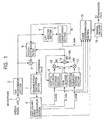
- FIG. 5 shows an example of the configuration of the receiving section 114 of Fig. 4.
- Components in Fig. 5 corresponding to the case in Fig. 2 are given the same reference numerals, and in the following, descriptions thereof are omitted where appropriate.
- Synthesized speech data for each subframe, which is output from the speech synthesis filter 29, and the L code among the L code, the G code, the I code, and the A code for each subframe, which are output from the channel decoder 21, are supplied to the tap generation sections 121 and 122.
- the tap generation sections 121 and 122 extract data used as a prediction tap used to predict the prediction value of high-quality sound and data used as a class tap used for classification from the synthesized speech data and the I code supplied to the tap generation sections 121 and 122, respectively.
- the prediction tap is supplied to a prediction section 125, and the class tap is supplied to a classification section 123.
- the classification section 123 performs classification on the basis of the class tap supplied from the tap generation section 122, and supplies the class code as the classification result to a coefficient memory 124.
- a classification method in the classification section 123 there is a method using, for example, a K-bit ADRC (Adaptive Dynamic Range Coding) process.
- ADRC Adaptive Dynamic Range Coding
- each piece of data which forms the class tap is requantized to K bits. That is, the minimum value MIN is subtracted from each piece of data which forms the class tap, and the subtracted value is divided (quantized) by DR/2 K . Then, a bit sequence in which the values of the K bits of each piece of data which forms the class tap are arranged in a predetermined order is output as an ADRC code.
- a bit sequence in which the values of the K-bit of each of data which forms a prediction tap obtained as a result of the K-bit ADRC process are arranged in a predetermined order is assumed to be a class code.
- the classification can also be performed by considering a class tap as a vector in which each piece of data which forms the class tap is an element and by performing vector quantization on the class tap as the vector.
- the coefficient memory 124 stores tap coefficients for each class, obtained as a result of a learning process being performed in the learning apparatus of Fig. 13, which will be described later, and supplies to the prediction section 125 a tap coefficient stored at the address corresponding to the class code output from the classification section 123.
- the prediction section 125 obtains the prediction tap output from the tap generation section 121 and the tap coefficient output from the coefficient memory 124, and performs the linear prediction computation shown in equation (6) by using the prediction tap and the tap coefficient. As a result, the prediction section 125 determines (the prediction value of the) high-quality sound with respect to the subject subframe of interest and supplies the value to the D/A conversion section 30.
- the channel decoder 21 separates an L code, a G code, an I code, and an A code from the code data supplied thereto, and supplies the codes to the adaptive codebook storage section 22, the gain decoder 23, the excitation codebook storage section 24, and the filter coefficient decoder 25, respectively. Furthermore, the L code is also supplied to the tap generation sections 121 and 122.
- the adaptive codebook storage section 22, the gain decoder 23, the excitation codebook storage section 24, and arithmetic units 26 to 28 perform the same processes as in the case of Fig. 2, and as a result, the L code, the G code, and the I code are decoded into a residual signal e. This residual signal is supplied to the speech synthesis filter 29.
- the filter coefficient decoder 25 decodes the A code supplied thereto into a linear prediction coefficient and supplies it to the speech synthesis filter 29.
- the speech synthesis filter 29 performs speech synthesis by using the residual signal from the arithmetic unit 28 and the linear prediction coefficient from the filter coefficient decoder 25, and supplies the resulting synthesized speech to the tap generation sections 121 and 122.
- the tap generation section 121 assumes the subframe of the synthesized speech which is output in sequence by the speech synthesis filter 29 to be a subject subframe in sequence.
- the tap generation section 121 generates a prediction tap from the synthesized speech of the subject subframe and the I code of the subframe, which will be described later, and supplies the prediction tap to the prediction section 125.
- the tap generation section 122 also generate a class tap from the synthesized speech of the subject subframe, and the I code of the subframe, which will be described later, and supplies the class tap to the classification section 123.
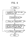
- step S2 the classification section 123 performs classification on the basis of the class tap supplied from the tap generation section 122, and supplies the resulting class code to the coefficient memory 124, and then the process proceeds to step S3.
- step S3 the coefficient memory 124 reads a tap coefficient from the address corresponding to the class code supplied from the classification section 123, and supplies the tap coefficient to the prediction section 125.
- step S4 the prediction section 125 obtains the tap coefficient output from the coefficient memory 124, and performs the sum-of-products computation shown in equation (6) by using the tap coefficient and the prediction tap from the tap generation section 121, so that (the prediction value of) the high-quality sound data of the subject subframe is obtained.
- steps S1 to S4 are performed by using each of the sample values of the synthesized speech data of the subject subframe in sequence as subject data. That is, since the synthesized speech data of the subframe is composed of 40 samples, as described above, the processes of steps S1 to S4 are performed for each of the synthesized speech data for the 40 samples.
- the high-quality sound obtained in the above-described manner is supplied from the prediction section 125 via the D/A conversion section 30 to a speaker 31, whereby high-quality sound is output from the speaker 31.
- step S4 the process proceeds to step S5, where it is determined whether or not there are any more subframes to be processed as subject subframes.
- step S5 it is determined whether or not there are any more subframes to be processed as subject subframes.
- the process returns to step S1, where a subframe to be used as the next subject subframe is newly used as a subject subframe, and hereafter, the same processes are repeated.
- step S5 it is determined that there is no subframe to be processed as a subject subframe, the processing is terminated.
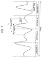
- the tap generation section 121 assumes each synthesized speech data (the synthesized speech data output from the speech synthesis filter 29) of the subframe to be subject data, and extracts, as a prediction tap, the synthesized speech data of past N samples (the synthesized speech data in the range shown in A in Fig. 7) from the subject data and the past and future synthesized speech data of a total of N samples (the synthesized speech data in the range shown in B in Fig. 7) with the subject data being the center.
- the tap generation section 121 also extracts, for example, as a prediction tap, the subframe (subframe #3 in the embodiment of Fig. 7) at which the subject data is positioned, that is, the I code located in the subject subframe.
- the prediction tap is formed of the synthesized speech data of N samples containing the subject data, and the I code of the subject subframe.
- tap generation section 122 for example, in the same manner as in the case of tap generation section 121, a class tap formed of synthesized speech data and the I code is extracted.
- the structure pattern of the prediction tap and the class tap are not limited to the above-described patterns. That is, as the prediction tap and the class tap, in addition to extracting, from the subject data, the synthesized speech data of all the N samples such as that described above, it is possible to extract synthesized speech data every other sample.
- the class tap and the prediction tap are formed in the same ways, the class tap and the prediction tap can be formed in different ways.
- the prediction tap and the class tap can be formed only from synthesized speech data. However, in the manner described above, also, by forming the prediction tap and the class tap by using the I code as information related to the synthesized speech data in addition to the synthesized speech data, it becomes possible to decode higher-quality sound.
- the synthesized speech data which is used as the prediction tap contains not only the synthesized speech data of the subject subframe, but also the synthesized speech data of the subframe immediately before. Therefore, in this case, if the I code located in the subject subframe is to be contained in the prediction tap, unless the I code located in the subframe immediately before is contained in the prediction tap, there is a risk in that the relationship between the synthesized speech data which forms the prediction tap, and the I code does not become a balanced one.
- the subframe of the I code from which the prediction tap and the class tap are formed can be made variable according to the position of the subject data in the subject subframe.
- the synthesized speech data contained in the prediction tap which is formed from the subject data extends up to the subframe adjacent immediately before or after the subject subframe (hereinafter referred to as an "adjacent subframe") or in a case where the synthesized speech data extends up to a position near the adjacent subframe, it is possible to form the prediction tap so as to contain not only the I code of the subject subframe, but also the I code of the adjacent subframe.
- the class tap can also be formed in the same manner.
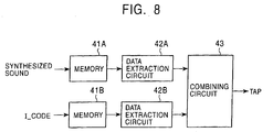
- Fig. 8 shows an example of the configuration of the tap generation section 121 for forming the prediction tap so as to be able to achieve a balance between the synthesized speech data and the I code, which form the prediction tap, by making the subframe of the I code which forms the prediction tap variable according to the position of the subject data in the subject subframe in the above-described manner.
- the tap generation section 122 for forming a class tap can also be formed similarly to that of Fig. 8.
- the synthesized speech data output from the speech synthesis filter 29 of Fig. 5 is supplied to a memory 41A, and the memory 41A temporarily stores the synthesized speech data supplied thereto.
- the memory 41A has at least a storage capacity capable of storing the synthesized speech data of N samples which form one prediction tap. Furthermore, the memory 41A stores the latest sample of the synthesized speech data supplied thereto in sequence in such a manner as to overwrite on the oldest stored value.
- a data extraction circuit 42A extracts, from the subject data, the synthesized speech data which forms the prediction tap by reading it from the memory 41A, and outputs the synthesized speech data to a combining circuit 43.
- the data extraction circuit 42A extracts the synthesized speech data of past N samples from the latest synthesized speech data by reading it from the memory 41A, and outputs the data to the combining circuit 43.
- the synthesized speech data in the past by N/2 (decimal places are, for example, raised to the next whole number) samples from the latest synthesized speech data within the synthesized speech data stored in the memory 41A may be assumed to be subject data, and past and future synthesized speech data of a total of N samples with the subject data being the center may be read from the memory 41A.
- the I codes in subframe units, output from the channel decoder 21 of Fig. 5, are supplied to a memory 41B, and the memory 41B temporarily stores the I code supplied thereto.
- the memory 41B has at least a storage capacity capable of storing I codes for an amount capable of forming one prediction tap. Furthermore, similarly to the memory 41A, the memory 41B stores the latest I code supplied thereto in such a manner as to overwrite on the oldest stored value.
- a data extraction circuit 42B extracts only the I code of the subject subframe, or the I code of the subject subframe and the I code of the subframe adjacent to the subject subframe (adjacent subframe) by reading them from the memory 41B according to the position of the synthesized speech data which is assumed to be subject data by the data extraction circuit 42A in the subject subframe, and outputs them to the combining circuit 43.
- the combining circuit 43 combines (merges) the synthesized speech data from the data extraction circuit 42A and the I code from the data extraction circuit 42B into one set of data, and outputs it as the prediction tap.
- the synthesized speech data which forms the prediction tap is fixed at N samples.
- the I code there is a case in which it is only the I code of the subject subframe, and there is a case in which it is the I code of the subject subframe and the I code of the subframe adjacent to the subject subframe (adjacent subframe). Therefore, the number of the I codes varies. This applies the same to the class tap generated in the tap generation section 122.
- the number of taps which form the class tap varies, the number of all the classes obtained by the class tap varies, presenting the risk that the processing becomes complex. Therefore, it is preferable that classification in which, even if the number of taps of the class tap varies, the number of classes obtained by the class tap does not vary be performed.
- the number of taps of the class tap increases or decreases according to the position of the subject data in the subject subframe. For example, it is assumed that there are cases in which the number of taps of the class tap is S and L which is greater than S (> S), and when the number of taps is S, a class of n bits is obtained, and when the number of taps is L, a class code of n + m bits is obtained.
- n + m + 1 bits are used, and, for example, 1 bit, such as the highest-order bit, within the n + m + 1 bits is set to, for example, "0" and "1" depending on the case in which the number of class taps is S and L.
- 1 bit such as the highest-order bit
- the number of class taps is S and L.
- classification in which a class code of n + m bits is obtained may be performed, and n + m + 1 bits such that "1" as the highest-order bit indicating that the number of taps is L is added to the class code of the n + m bits may be assumed to be the final class code.
- classification in which a class code of n bits is obtained may be performed, "0" of m bits as the high-order bits may be added to the class code of the n bits so as to be formed as n + m bits, and n + m + 1 bits such that "0", as the highest-order bit, indicating that the number of class taps is S is added to the n + m bits may be assumed to be the final class code.
- classification can be performed by providing a weight to the data which forms the class tap.
- the synthesized speech data of N samples which is past from the subject data, shown in A in Fig. 7 is to be contained in a class tap
- one or both of the I code of the subject subframe hereinafter referred to as a "subject subframe #n" where appropriate
- the I code of subframe #n-1 immediately before are to be contained in the class tap according to the position of the subject data in the subject subframe, for example, weighting such as that shown in Fig. 9A is performed to the number of classes corresponding to the I code of the subject subframe #n which forms the class tap and the number of classes corresponding to the I code of the subframe #n-1 immediately before, allowing the number of classes to be fixed.
- Fig. 9A shows that classification is performed in which the more to the right (future) of the subject subframe #n the subject data is positioned, the more the number of classes corresponding to the I code of subject subframe #n is increased. Furthermore, Fig. 9A shows that classification is performed in which the more to the right of the subject subframe #n the subject data is positioned, the more the number of classes corresponding to the I code of subframe #n-1 immediately before is decreased. As a result of weighting such as that shown in Fig. 9A being performed, classification in which the overall number of classes becomes fixed is performed.
- weighting such as that shown in Fig. 9B is performed to the number of classes corresponding to the I code of the subject subframe #n which forms the class tap, the number of classes corresponding to the I code of subframe #n-1 immediately before, and the I code of the number of classes corresponding to the I code of subframe #n+1 immediately after, allowing the number of classes to be fixed.
- Fig. 9B shows that classification in which the more close to the center position of the subject subframe #n the subject data is, the more the number of classes corresponding to the I code of subject subframe #n is increased. Furthermore, Fig. 9B shows that classification in which the more to the left (in the past) of subject subframe #n the subject data is positioned, the more the number of classes corresponding to the I code of subframe #n-1 immediately before the subject subframe #n is increased, and the more to the right (in the future) of the subject subframe #n the subject data is positioned, the more the number of classes corresponding to the I code of subject subframe #n+1 immediately after subject subframe #n is increased. As a result of weighting such as that shown in Fig. 9B being performed, classification in which the overall number of classes becomes fixed is performed.
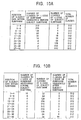
- Fig. 10 shows an example of weighting in a case where classification in which the number of classes corresponding to the I code becomes fixed at 512.
- Fig. 10A shows a specific example of weighting shown in Fig. 9A in a case where one or both of the I code of subject subframe #n and the I code of subframe #n-1 immediately before are contained in the class tap according to the position of the subject data in the subject subframe.
- Fig. 10B shows a specific example of weighting shown in Fig. 9B in a case where the I code of subject subframe #n, and one or both of the I code of subject subframe #n-1 immediately before and the I code of subframe #n+1 immediately after are contained in the class tap according to the position the subject data in the subject subframe.
- the leftmost column shows the position of the subject data in the subject subframe from the left end.
- the second column from the left shows the number of classes by the I code of the subframe immediately before the subject subframe.
- the third column from the left shows the number of classes by the I code of the subject subframe.
- the rightmost column shows the number of classes by the I code which forms the class tap (the number of classes by the I code of the subject subframe and the I code of the subframe immediately before).
- the position of the subject data in the subject subframe from the left end (the leftmost column) takes a value in the range of 1 to 40.
- Fig. 10A the same applies in Fig. 10B, which will be described later
- weighting is performed to the number of classes by the I code of the subject subframe and the number of classes by the I code of the subframe immediately before so that the number of classes by all the I codes which form the class tap (the number of classes by the I code of the subject subframe and by the I code of the subframe immediately before) becomes 512, that is, the product of the number of classes by the I code of the subject subframe and the number of classes by the I code of the subframe immediately before becomes 512.
- Fig. 10A as described in Fig. 9A, the more to the right of subject subframe #n the subject data is positioned (the more the value indicating the position of the subject data is increased), the more the number of classes corresponding to the I code of subject subframe #n is increased and the number of classes corresponding to the I code of subframe #n-1 immediately before subject subframe #n is decreased.
- Fig. 10B the leftmost column, the second column from the left, the third column from the left, and the rightmost column show the same contents as in the case of Fig. 10A.
- the fourth column from the left shows the number of classes by the I code of the subframe immediately after the subject subframe.
- Fig. 10B as described in Fig. 9B, the more away from the center position of subject subframe #n the subject data is (the more the value indicating the position of the subject data is increased or decreased), the number of classes corresponding to the I code of subject subframe #n is decreased. Furthermore, the more to the left of subject subframe #n the subject data is positioned, the more the number of classes corresponding to the I code of subframe #n-1 immediately before subject subframe #n is increased. In addition, the more to the right of subject subframe #n the subject data is positioned, the more the number of classes corresponding to the I code of subframe #n+1 immediately after subject subframe #n is increased.
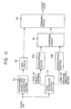
- Fig. 11 shows an example of the configuration of the classification section 123 of Fig. 5 for performing classification involving weighting such as that described above.
- the class tap is composed of, for example, the synthesized speech data of N samples in the past from the subject data, and the I codes of the subject data and the subframe immediately before, shown in A in Fig. 7.
- the class tap output from the tap generation section 122 (Fig. 5) is supplied to a synthesized speech-data extraction section 51 and a code extraction section 53.
- the synthesized speech-data extraction section 51 cuts out (extracts), from a class tap supplied thereto, synthesized speech data of a plurality of samples forming the class tap, and supplies the synthesized speech data to an ADRC circuit 52.
- the ADRC circuit 52 performs, for example, a one-bit ADRC process on a plurality of items of synthesized speech data (here, the synthesized speech data of N samples) supplied from the synthesized speech-data extraction section 51, and supplies a bit sequence, in which one bit for a plurality of items of resulting synthesized speech data is arranged in a predetermined order, to a combining circuit 56.
- the code extraction section 53 cuts out (extracts) the I code which forms the class tap from the class tap supplied thereto. Furthermore, the code extraction section 53 supplies the I code of the subject subframe and the I code of the subframe immediately before among the cutout I codes to degeneration section 54A and 54B, respectively.
- the degeneration section 54A stores a degeneration table created by a table creation process (to be described later). In the manner described in Figs. 9 and 10, by using the degeneration table, the degeneration section 54A degenerates (decreases) the number of classes represented by the I code of the subject subframe according to the position of the subject data in the subject subframe, and supplies the number of classes to a synthesis circuit 55.
- the degeneration section 54A performs a degeneration process so that, for example, as shown in Fig. 10A, the number of classes of 512 represented by the I code of the subject subframe is made to be 512, that is, an I code of 9 bits of the subject subframe is not particularly processed and is directly output.
- the degeneration section 54A performs a degeneration process so that the number of classes of 512 indicated by the I code of the subject subframe becomes 256, that is, the I code of 9 bits of the subject subframe is converted into a code indicated by 8 bits by using a degeneration table, and this code is output.
- a degeneration section 54A performs a degeneration process so that the number of classes of 512 indicated by the I code of the subject subframe becomes 128, that is, the I code of 9 bits of the subject subframe is converted into a code indicated by 7 bits by using the degeneration table, and code this is output.
- the degeneration section 54A degenerates the number of classes indicated by the I code of the subject subframe as shown in the second column from the left of Fig. 10A according to the position of the subject data in the subject subframe, and outputs the number of classes to a combining circuit 55.
- the degeneration section 54B also stores a degeneration table similarly to the degeneration section 54A. By using the degeneration table, the degeneration section 54B degenerates the number of classes indicated by the I code of the subframe as shown in the third column from the left of Fig. 10A according to the position of the subject data in the subject subframe, and outputs the number of classes to the combining circuit 55.
- the combining circuit 55 combines the I code of the subject subframe in which the number of classes is degenerated as appropriate, from the degeneration section 54A, and the I code of the subframe immediately before the subject subframe, in which the number of classes is degenerated as appropriate, from the degeneration circuit 54B, into one bit sequence, and supplies the bit sequence to a combining circuit 56.
- the combining circuit 56 combines the bit sequence output from the ADRC circuit 52 and the bit sequence output from the combining circuit 55 into one bit sequence, and supplies the bit sequence as a class code.
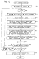
- a number of classes M after degeneration is set.
- M is set as a value which is raised to a power of 2.
- M is set to a value of 512 which is the maximum number of classes indicated by an I code of 9 bits or lower.
- step S12 a variable c indicating the class code after degeneration is set to "0"
- step S13 all the I codes (first, all the numbers indicated by the I code of 9 bits) are set as object I codes for the object of processing, and the process proceeds to step S14.
- step S14 one of the object I codes is selected as a subject I code, and the process proceeds to step S15.
- step S15 the square error of a waveform represented by the I code (waveform of an excitation signal) and each of waveforms represented by all the object codes is calculated.
- the I code corresponds to a predetermined excitation signal.
- the sum of the square errors of each sample value of the waveform of the excitation signal represented by the subject I code and the corresponding sample value of the waveform of the excitation signal represented by the object I codes is determined.
- such a sum of square error for the subject I codes is determined by using all the object I codes as objects.
- step S16 the object I code at which the sum of the square errors for the subject I code is minimized (hereinafter referred to as a "least-square error I code" where appropriate) is detected, and the subject I code and the least-square error I code are made to correspond to the code represented by the variable c. That is, as a result, the subject I code, and the object I code representing the waveform which most resembles the waveform represented by the subject I code (the least-square error I code) among the object I codes are degenerated into the same class c.
- the object I code at which the sum of the square errors for the subject I code is minimized hereinafter referred to as a "least-square error I code" where appropriate
- step S16 the process proceeds to step S17, where, for example, an average value of each sample value of the waveform represented by the subject I code and the corresponding sample value of the waveform represented by the least-square error I code is determined, and the waveform by the average value is, as the waveform of the excitation signal represented by the variable c, made to correspond to the variable c.
- step S18 where the subject I code and the least-square error I code are excluded from the object I codes.
- step S19 where the variable c is incremented by 1, and the process proceeds to step S20.
- step S20 it is determined whether or not there is an I code for an object I code.
- the process returns to step S14, where a new subject I code is selected from the I code for an object I code, and hereafter, the same processes are repeated.
- step S20 When it is determined in step S20 that there is no I code for an object I code, that is, when the I code which is made to be an object I code in the previous step S13 is made to correspond to variables c in a number of 1/2 of the total number of the I codes, the process proceeds to step S21, where it is determined whether or not the variable c is equal to the number of classes M after degeneration.
- step S21 When it is determined in step S21 that the variable c is not equal to the number of classes M after degeneration, that is, when the number of classes represented by the I code of 9 bits is not yet degenerated into the M classes, the process proceeds to step S22, where each value represented by the variable c is newly assumed to be an I code. Then, the process returns to step S12, and hereafter, by using the new I code as an object, the same processes are repeated.
- step S15 by using the waveform determined in step S17 as a waveform of the excitation signal indicated by the new I code, the square error in step S15 is calculated.
- step S21 when it is determined in step S21 that the variable c is equal to the number of classes M after degeneration, that is, when the number of classes represented by the I code of 9 bits is degenerated into the M classes, the process proceeds to step S23, where a correspondence table between each value of the variables c and the I code of 9 bits corresponding to the value is created, the correspondence table is output as a degeneration table, and the processing is then terminated.
- the I code of the 9 bits supplied thereto is degenerated as a result of being converted into a variable c which is made to correspond to the I code of the 9 bits in the degeneration table created in the above-described manner.
- the degeneration of the number of classes by the I code of the 9 bits can also be performed by simply deleting the low-order bits of the I code.
- the degeneration of the number of classes be performed in such a manner that the resembling classes are collected. Therefore, instead of simply deleting the low-order bits of the I code, as described in Fig. 12, the I codes indicating the excitation signal having resembling waveforms are preferably assigned to the same class.
- Fig. 13 shows an example of the configuration of an embodiment of a learning apparatus for performing a process of learning tap coefficients stored in the coefficient memory 124 of Fig. 5.
- a series of components from a microphone 201 to a code determination section 215 are formed similarly to the series of components from the microphone 1 to the code determination section 15 of Fig. 1, respectively.
- a learning speech signal of high quality is input to the microphone 1, and therefore, in the microphone 201 to the code determination section 215, the same processes as in the case of Fig. 1 are performed on the learning speech signal.
- the code determination section 215 outputs only the L codes which form the prediction tap and the class tap in this embodiment among the L code, the G code, the I code, and the A code.
- the synthesized speech output by the speech synthesis filter 206 when it is determined in the least-square error determination section 208 that the square error reaches a minimum is supplied to tap generation sections 131 and 132. Furthermore, an I code which is output by the code determination section 215 when the code determination section 215 receives a determination signal from the least-square error determination section 208 is also supplied to the tap generation sections 131 and 132. Furthermore, speech output by an A/D conversion section 202 is supplied as teacher data to a normalization equation addition circuit 134.
- the generation section 131 generates the same prediction tap as in the case of the tap generation section 121 of Fig. 5 from the synthesized speech data output from the speech synthesis filter 206 and the I code output from the code determination section 215, and supplies the prediction tap as student data to the normalization equation addition circuit 134.
- the tap generation section 132 also generates the same class tap as in the case of the tap generation section 122 of Fig. 5 from the synthesized speech data output from the speech synthesis filter 206 and the I code output from the code determination section 215, and supplies the class tap to a classification section 133.
- the classification section 133 performs the same classification as in the case of the classification section 123 of Fig. 5 on the basis of the class tap from the tap generation section 132, and supplies the resulting class code to the normalization equation addition circuit 134.
- the normalization equation addition circuit 134 receives speech from the A/D conversion section 202 as teacher data, and receives the prediction tap from the generation section 131 as student data, and performs addition for each class code from the classification section 133 by using the teacher data and the student data as objects.
- the normalization equation addition circuit 134 performs, for each class corresponding to the class code supplied from the classification section 133, multiplication of the student data (x in x im ) which is each component in the matrix A of equation (13), and a computation equivalent to summation ( ⁇ ), by using the prediction tap (student data).
- the normalization equation addition circuit 134 also performs, for each class corresponding to the class code supplied from the classification section 133, multiplication of the student data and the teacher data (x in y i ) which is each component in the vector v of equation (13), and a computation equivalent to summation ( ⁇ ), by using the student data and the teacher data.
- the normalization equation addition circuit 134 performs the above-described addition by using all the subframes of the speech for learning supplied thereto as the subject subframes. As a result, a normalization equation shown in equation (13) is formulated for each class.
- a tap coefficient determination circuit 135 determines the tap coefficient for each class by solving the normalization equation generated for each class in the normalization equation addition circuit 134, and supplies the tap coefficient to the address, corresponding to each class, of the coefficient memory 136.
- a class may occur at which normalization equations of a number required to determine the tap coefficient are not obtained.
- the tap coefficient determination circuit 135 outputs, for example, a default tap coefficient.
- the coefficient memory 136 stores the tap coefficient for each class supplied from the tap coefficient determination circuit 135 at an address corresponding to that class.
- a learning speech signal is supplied to the learning apparatus.
- teacher data and student data are generated from the learning speech signal.
- the learning speech signal is input to the microphone 201, and the microphone 201 to the code determination section 215 perform the same processes as in the case of the microphone 1 to the code determination section 15 in Fig. 1, respectively.
- the speech of the digital signal obtained by the A/D conversion section 202 is supplied as teacher data to the normalization equation addition circuit 134. Furthermore, when it is determined in the least-square error determination section 208 that the square error reaches a minimum, the synthesized speech data output from the speech synthesis filter 206 is supplied as student data to the tap generation sections 131 and 132. Furthermore, the I code output from the code determination section 215 when it is determined in the least-square error determination section 208 that the square error reaches a minimum is also supplied as student data to the tap generation sections 131 and 132.
- step S32 the tap generation section 131 assumes, as the subject subframe, the subframe of the synthesized speech supplied as student data from the speech synthesis filter 206, and further assumes the synthesized speech data of that subject subframe in sequence as the subject data, generates, with respect to each of subject data, a prediction tap similarly to the case in the tap generation section 121 of Fig. 5 from the synthesized speech data from the speech synthesis filter 206 and the L code from the code determination section 215, and supplies the prediction tap to the normalization equation addition circuit 134. Furthermore, in step S32, the tap generation section 132 also generates a class tap from the synthesized speech data similarly to the case in the tap generation section 122 of Fig. 5, and supplies the class tap to the classification section 133.
- step S32 the process proceeds to step S33, where the classification section 133 performs classification on the basis of the class tap from the tap generation section 132, and supplies the resulting class code to the normalization equation addition circuit 134.
- step S34 the normalization equation addition circuit 134 performs addition of the matrix A and the vector v of equation (13), such as that described above, for each class code with respect to the subject data, from the classification section 133, by using as objects speech within the learning speech as teacher data from the A/D conversion section 202, which corresponds to the subject data, and the prediction tap (the prediction tap generated from the subject data) as the student data from the tap generation section 132. Then, the process proceeds to step S35.
- step S35 it is determined whether or not there are any more subframes to be processed as subject subframes.
- the process returns to step S31, where the next subframe is newly assumed to be a subject subframe, and hereafter, the same processes are repeated.
- step S35 when it is determined in step S35 that there is no subframe to be processed as a subject subframe, the process proceeds to step S36, where the tap coefficient determination circuit 135 solves the normalization equation generated for each class in the normalization equation addition circuit 134 in order to determine the tap coefficient for each class, supplies the tap coefficient to the address, corresponding to each class, of the coefficient memory 136, whereby the tap coefficient is stored, and the processing is then terminated.
- the tap coefficient for each class stored in the coefficient memory 136, is stored in the coefficient memory 124 of Fig. 5.
- the tap coefficient stored in the coefficient memory 124 of Fig. 5 is determined in such a way that learning is performed so that the prediction error (square error) of a speech prediction value of high-quality speech, obtained by performing a linear prediction computation, statistically becomes a minimum, the speech output by the prediction section 125 of Fig. 5 becomes high-sound quality.
- the prediction tap and the class tap can be formed so as to contain, instead of the I code or in addition to the I code, one or more of the I code, the L code, the G code, the A code, a linear prediction coefficient ⁇ p obtained from the A code, a gain ⁇ or ⁇ obtained from the G code, and other information (for example, an residual signal e, l or n for obtaining the residual signal e, further, l/ ⁇ , n/ ⁇ , etc.) obtained from the L code, the G code, the I code, or the A code.
- the prediction tap and the class tap can also be formed so as to use soft interpolation bits and frame energy.
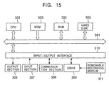
- Fig. 15 shows an example of the configuration of an embodiment of a computer into which programs for executing the above-described series of processes are executed are installed.
- the programs can be prerecorded in a hard disk 305 and a ROM 303 as a recording medium built into the computer.
- the programs may be temporarily or permanently stored (recorded) in a removable recording medium 311, such as a floppy disk, a CD-ROM (Compact Disc Read Only Memory), an MO (Magneto optical) disk, a DVD (Digital Versatile Disc), a magnetic disk, or a semiconductor memory.
- a removable recording medium 311 may be provided as what is commonly called packaged software.
- programs may be transferred in a wireless manner from a download site via an artificial satellite for digital satellite broadcasting or may be transferred by wire to a computer via a network, such as a LAN (Local Area Network) or the Internet, and in the computer, the programs which are transferred in such a manner are received by a communication section 308 and can be installed into the hard disk 305 contained therein.
- a network such as a LAN (Local Area Network) or the Internet
- the computer has a CPU (Central Processing Unit) 302 contained therein.
- An input/output interface 310 is connected to the CPU 302 via a bus 301.
- the CPU 302 executes a program stored in the ROM (Read Only Memory) 303 in accordance with the command.
- the CPU 302 loads a program stored in the hard disk 305, a program which is transferred from a satellite or a network, which is received by the communication section 308, and which is installed into the hard disk 305, or a program which is read from the removable recording medium 311 loaded into a drive 309 and which is installed into the hard disk 305, to a RAM (Random Access Memory) 304, and executes the program.
- the CPU 302 performs processing in accordance with the above-described flowcharts or processing performed according to the constructions in the above-described block diagrams.
- the CPU 302 outputs the processing result, for example, from an output section 306 formed of an LCD (Liquid Crystal Display), a speaker, etc., via the input/output interface 310, as required, or transmits the processing result from the communication section 308, and furthermore, records the processing result in the hard disk 305.
- an output section 306 formed of an LCD (Liquid Crystal Display), a speaker, etc.
- processing steps which describe a program for causing a computer to perform various types of processing need not necessarily perform processing in a time series along the described sequence as a flowchart and contain processing performed in parallel or individually (for example, parallel processing or object-oriented processing) as well.
- a program may be such that it is processed by one computer or may be such that it is processed in a distributed manner by plural computers.
- a program may be such that it is transferred to a remote computer and is executed thereby.
- tap coefficients are stored in advance in the coefficient memory 124, etc., in the mobile phone 101
- the tap coefficients to be stored in the coefficient memory 124, etc. can be downloaded from the base station 102 (or the exchange 103) of Fig. 3, a WWW (World Wide Web) server (not shown), etc. That is, as described above, tap coefficients suitable for certain kinds of speech signals, such as for human speech production or for a musical piece, can be obtained through learning. Furthermore, depending on teacher data and student data used for learning, tap coefficients by which a difference occurs in the sound quality of synthesized speech can be obtained. Therefore, such various kinds of tap coefficients can be stored in the base station 102, etc., so that a user is made to download tap coefficients desired by the user. Such a downloading service of tap coefficients can be performed free or for a charge. Furthermore, when downloading service of tap coefficients is performed for a charge, the cost for downloading the tap coefficients can be charged, for example, together with the charge for telephone calls of the mobile phone 101.
- the coefficient memory 124, etc. can be formed by a removable memory card which can be loaded into and removed from the mobile phone 101, etc.
- a removable memory card which can be loaded into and removed from the mobile phone 101, etc.
- different memory cards in which various types of tap coefficients, such as those described above, are stored are provided, it becomes possible for the user to load a memory card in which desired tap coefficients are stored into the mobile phone 101 and to use it depending on the situation.
- the present invention can be widely applied to a case in which, for example, synthesized speech is produced from codes obtained as a result of coding by a CELP method such as VSELP (Vector Sum Excited Linear Prediction), PSI-CELP (Pitch Synchronous Innovation CELP), or CS-ACELP (Conjugate Structure Algebraic CELP).
- VSELP Vector Sum Excited Linear Prediction
- PSI-CELP Pitch Synchronous Innovation CELP
- CS-ACELP Conjugate Structure Algebraic CELP
- the present invention is not limited to the case where synthesized speech is decoded from codes obtained as a result of coding by a CELP method, and can be widely applied to a case in which the original data is decoded from coded data having information (decoding information) used for decoding in predetermined units. That is, the present invention can also be applied to coded data such that, for example, an image is coded by a JPEG (Joint Photographic Experts Group) method having a DCT (Discrete Cosine Transform) coefficient in predetermined block units.
- JPEG Joint Photographic Experts Group
- DCT Discrete Cosine Transform
- prediction values of a residual signal and a linear prediction coefficient are determined by linear first-order prediction computation using tap coefficients, additionally, these prediction values can also be determined by high-order prediction computation of a second or higher order.
- Japanese Unexamined Patent Application Publication No. 8-202399 a method in which the sound quality of synthesized speech is improved by causing the synthesized speech to pass through a high-frequency accentuation filter is disclosed.
- the present invention differs from the invention described in Japanese Unexamined Patent Application Publication No. 8-202399 in that a tap coefficient is obtained through learning, a tap coefficient used for prediction calculation is adaptively determined according to classification results, and further, the prediction tap, etc. is generated not only from synthesized speech, but is also generated from an I code, etc., contained in coded data.
- a tap used for a predetermined process is generated by extracting decoded data in a predetermined positional relationship with subject data of interest within the decoded data such that coded data is decoded and by extracting decoding information in predetermined units according to a position of the subject data in predetermined units, and the predetermined process is performed by using the tap. Therefore, for example, it becomes possible to obtain high-quality decoded data.
- decoded data as student data serving as a student is generated by coding teacher data serving as a teacher into coded data having decoding information in predetermined units and by decoding the coded data. Furthermore, a prediction tap used to predict teacher data is generated by extracting decoded data in a predetermined positional relationship with subject data of interest within the decoded data as the student data and by extracting the decoding information in predetermined units according to a position of the subject data in predetermined units. Then, learning is performed so that a prediction error of the prediction value of the teacher data obtained by performing a predetermined prediction computation by using the prediction tap and the tap coefficient statistically becomes a minimum, and the tap coefficient is determined. Therefore, it becomes possible to obtain a tap coefficient for decoding high-quality decoded data from the coded data.
Landscapes
- Engineering & Computer Science (AREA)
- Computational Linguistics (AREA)
- Signal Processing (AREA)
- Health & Medical Sciences (AREA)
- Audiology, Speech & Language Pathology (AREA)
- Human Computer Interaction (AREA)
- Physics & Mathematics (AREA)
- Acoustics & Sound (AREA)
- Multimedia (AREA)
- Compression, Expansion, Code Conversion, And Decoders (AREA)
Abstract
The present invention relates to a data processing
apparatus capable of obtaining high-quality sound data. A
tap generation section 121 generates a prediction tap used
for a process in a prediction section 125 by extracting
decoded speech data in a predetermined positional
relationship with subject data of interest within the
decoded speech data such that coded data is decoded by a
CELP method and by extracting an I code located in a
subframe according to a position of the subject data in the
subject subframe. Similarly to the tap generation section
122, a tap generation section 122 generates a class tap used
for a process in a classification section 123. The
classification section 123 performs classification on the
basis of the class tap, and a coefficient memory 124 outputs
a tap coefficient corresponding to the classification result.
The prediction section 125 performs a linear prediction
computation by using the prediction tap and the tap
coefficient and outputs high-quality decoded speech data.
The present invention can be applied to mobile phones for
transmitting and receiving speech.
Description
The present invention relates to a data processing
apparatus. More particularly, the present invention relates
to a data processing apparatus capable of decoding speech
which is coded by, for example, a CELP (Code Excited Linear
coding) method into high-quality speech.
Figs. 1 and 2 show the configuration of an example of a
conventional mobile phone.
In this mobile phone, a transmission process of coding
speech into a predetermined code by a CELP method and
transmitting the codes, and a receiving process of receiving
codes transmitted from other mobile phones and decoding the
codes into speech are performed. Fig. 1 shows a
transmission section for performing the transmission process,
and Fig. 2 shows a receiving section for performing the
receiving process.
In the transmission section shown in Fig. 1, speech
produced from a user is input to a microphone 1, whereby the
speech is converted into an speech signal as an electrical
signal, and the signal is supplied to an A/D
(Analog/Digital) conversion section 2. The A/D conversion
section 2 samples an analog speech signal from the
microphone 1, for example, at a sampling frequency of 8 kHz,
etc., so that the analog speech signal undergoes A/D
conversion from an analog signal into a digital speech
signal. Furthermore, the A/D conversion section 2 performs
quantization of the signal with a predetermined number of
bits and supplies the signal to an arithmetic unit 3 and an
LPC (Linear Prediction Coefficient) analysis section 4.
The LPC analysis section 4 assumes a length, for
example, of 160 samples of an speech signal from the A/D
conversion section 2 to be one frame, divides that frame
into subframes every 40 samples, and performs LPC analysis
for each subframe in order to determine linear predictive
coefficients α1, α2,..., αp of the P order. Then, the LPC
analysis section 4 assumes a vector in which these linear
predictive coefficient αp (p = 1, 2,..., P) of the P order
are elements, as a speech feature vector, to a vector
quantization section 5.
The vector quantization section 5 stores a codebook in
which a code vector having linear predictive coefficients as
elements corresponds to codes, performs vector quantization
on a feature vector α from the LPC analysis section 4 on the
basis of the codebook, and supplies the codes (hereinafter
referred to as an "A_code" as appropriate) obtained as a
result of the vector quantization to a code determination
section 15.
Furthermore, the vector quantization section 5 supplies
linear predictive coefficients α1', α2',..., αp', which are
elements forming a code vector α' corresponding to the
A_code, to a speech synthesis filter 6.
The speech synthesis filter 6 is, for example, an IIR
(Infinite Impulse Response) type digital filter, which
assumes a linear predictive coefficient αp' (p = 1, 2,...,
P) from the vector quantization section 5 to be a tap
coefficient of the IIR filter and assumes a residual signal
e supplied from an arithmetic unit 14 to be an input signal,
to perform speech synthesis.
More specifically, LPC analysis performed by the LPC
analysis section 4 is such that, for the (sample value) sn
of the speech signal at the current time n and past P sample
values sn-1, sn-2,..., sn-p adjacent to the above sample value,
a linear combination represented by the following equation
holds:
sn + α1 sn-1 + α2 sn-2 +...+ αp sn-p = en
and when linear prediction of a prediction value (linear
prediction value) sn' of the sample value sn at the current
time n is performed using the past P sample values sn-1, sn-2,..., sn-p on the basis of the following equation:
sn ' = -(α1 sn-1 + α2 sn-2 +...+ αp sn-p )
a linear predictive coefficient αp that minimizes the square
error between the actual sample value sn and the linear
prediction value sn' is determined.
Here, in equation (1), {en} (..., en-1, en, en+1,...) are
probability variables, which are uncorrelated with each
other, in which the average value is 0 and the variance is a
predetermined value σ2.
Based on equation (1), the sample value sn can be
expressed by the following equation:
sn = en - (α1 sn-1 + α2 sn-2 +...+ αp sn-p )
When this is subjected to Z-transformation, the following
equation is obtained:
S = E/(1 + α1 z-1 + α2 z-2 +...+ αp z-p )
where, in equation (4), S and E represent Z-transformation
of sn and en in equation (3), respectively.
Here, based on equations (1) and (2), en can be
expressed by the following equation:
en = sn - sn '
and this is called the "residual signal" between the actual
sample value sn and the linear prediction value sn'.
Therefore, based on equation (4), the speech signal sn
can be determined by assuming the linear predictive
coefficient αp to be a tap coefficient of the IIR filter and
by assuming the residual signal en to be an input signal of
the IIR filter.
Therefore, as described above, the speech synthesis
filter 6 assumes the linear predictive coefficient αp' from
the vector quantization section 5 to be a tap coefficient,
assumes the residual signal e supplied from the arithmetic
unit 14 to be an input signal, and computes equation (4) in
order to determine an speech signal (synthesized speech
data) ss.
In the speech synthesis filter 6, since a linear
predictive coefficient αp' as a code vector corresponding to
the code obtained as a result of the vector quantization is
used instead of the linear predictive coefficient αp
obtained as a result of the LPC analysis by the LPC analysis
section 4, that is, since a linear prediction coefficient α'
containing an quantization error is used, basically, the
synthesized speech signal output from the speech synthesis
filter 6 does not become the same as the speech signal
output from the A/D conversion section 2.
The synthesized speech signal ss output from the speech
synthesis filter 6 is supplied to the arithmetic unit 3.
The arithmetic unit 3 subtracts an speech signal s output by
the A/D conversion section 2 from the synthesized speech
data ss from the speech synthesis filter 6 (subtracts the
sample of the speech data s corresponding to that sample
from each sample of the synthesized speech data ss), and
supplies the subtracted value to a square-error computation
section 7. The A/D conversion section 7 computes the sum of
squares (sum of squares in units of subframes which form the
frame in which LPC analysis is performed by the LPC analysis
section 4) of the subtracted value from the arithmetic unit
3 and supplies the resulting square error to a least-square
error determination section 8.
The least-square error determination section 8 has
stored therein an L code (L_code) as a code indicating a lag,
a G code (G_code) as a code indicating a gain, and an I code
(I_code) as a code indicating a codeword (excitation
codebook) in such a manner as to correspond to the square
error output from the square-error computation section 7,
and outputs the L_code, the G code, and the L code
corresponding to the square error output from the square-error
computation section 7. The L code is supplied to an
adaptive codebook storage section 9. The G code is supplied
to a gain decoder 10. The I code is supplied to an
excitation-codebook storage section 11. Furthermore, the L
code, the G code, and the I code are also supplied to the
code determination section 15.
The adaptive codebook storage section 9 has stored
therein an adaptive codebook in which, for example, a 7-bit
L code corresponds to a predetermined delay time (long-term
prediction lag). The adaptive codebook storage section 9
delays the residual signal e supplied from the arithmetic
unit 14 by a delay time corresponding to the L code supplied
from the least-square error determination section 8 and
outputs the signal to an arithmetic unit 12. That is, the
adaptive codebook storage section 9 is formed of, for
example, memory, and delays the residual signal e from the
arithmetic unit 14 by the amount of samples corresponding to
the value indicated by the 7-bit record and outputs the
signal to the arithmetic unit 12.
Here, since the adaptive codebook storage section 9
delays the residual signal e by a time corresponding to the
L code and outputs the signal, the output signal becomes a
signal close to a period signal in which the delay time is a
period. This signal becomes mainly a driving signal for
generating synthesized speech of voiced sound in speech
synthesis using linear predictive coefficients.
A gain decoder 10 has stored therein a table in which
the G code corresponds to predetermined gains β and γ, and
outputs gains β and γ corresponding to the G code supplied
from the least-square error determination section 8. The
gains β and γ are supplied to the arithmetic units 12 and 13,
respectively. Here, the gain β is what is commonly called a
long-term filter status output gain, and the gain γ is what
is commonly called an excitation codebook gain.
The excitation-codebook storage section 11 has stored
therein an excitation codebook in which, for example, a 9-bit
I code corresponds to a predetermined excitation signal,
and outputs, to the arithmetic unit 13, the excitation
signal which corresponds to the I code supplied from the
least-square error determination section 8.
Here, the excitation signal stored in the excitation
codebook is, for example, a signal close to white noise, and
becomes mainly a driving signal for generating synthesized
speech of unvoiced sound in the speech synthesis using
linear predictive coefficients.
The arithmetic unit 12 multiplies the output signal of
the adaptive codebook storage section 9 with the gain β
output from the gain decoder 10 and supplies the multiplied
value 1 to the arithmetic unit 14. The arithmetic unit 13
multiplies the output signal of the excited codebook storage
section 11 with the gain γ output from the gain decoder 10
and supplies the multiplied value n to the arithmetic unit
14. The arithmetic unit 14 adds together the multiplied
value 1 from the arithmetic unit 12 with the multiplied
value n from the arithmetic unit 13, and supplies the added
value as the residual signal e to the speech synthesis
filter 6 and the adaptive codebook storage section 9.
In the speech synthesis filter 6, in the manner
described above, the residual signal e supplied from the
arithmetic unit 14 is filtered by the IIR filter in which
the linear predictive coefficient αp' supplied from the
vector quantization section 5 is a tap coefficient, and the
resulting synthesized speech data is supplied to the
arithmetic unit 3. Then, in the arithmetic unit 3 and the
square-error computation section 7, processes similar to the
above-described case are performed, and the resulting square
error is supplied to the least-square error determination
section 8.
The least-square error determination section 8
determines whether or not the square error from the square-error
computation section 7 has become a minimum (local
minimum). Then, when the least-square error determination
section 8 determines that the square error has not become a
minimum, the least-square error determination section 8
outputs the L code, the G code, and the I code corresponding
to the square error in the manner described above, and
hereafter, the same processes are repeated.
On the other hand, when the least-square error
determination section 8 determines that the square error has
become a minimum, the least-square error determination
section 8 outputs the determination signal to the code
determination section 15. The code determination section 15
sequentially latches the A code supplied from the vector
quantization section 5 and sequentially latches the L code,
the G code, and the I code supplied from the least-square
error determination section 8. When the determination
signal is received from the least-square error determination
section 8, the code determination section 15 supplies the A
code, the L code, the G code, and the I code, which are
latched at this time, to the channel encoder 16. The
channel encoder 16 multiplexes the A code, the L code, the G
code, and the I code from the code determination section 15
and outputs them as code data. This code data is
transmitted via a transmission path.
Based on the above, the code data is coded data having
the A code, the L code, the G code, and the I code, which
are information used for decoding, in units of subframes.
Here, the A code, the L code, the G code, and the I
code are determined for each subframe. However, for example,
there is a case in which the A code is sometimes determined
for each frame. In this case, to decode the four subframes
which form that frame, the same A code is used. However,
also, in this case, each of the four subframes which form
that one frame can be regarded as having the same A code.
In this way, the code data can be regarded as being formed
as coded data having the A code, the L code, the G code, and
the I code, which are information used for decoding, in
units of subframes.
Here, in Fig. 1 (the same applies also in Figs. 2, 5,
and 13, which will be described later), [k] is assigned to
each variable so that the variable is an array variable.
This k represents the number of subframes, but in the
specification, a description thereof is omitted where
appropriate.
Next, the code data transmitted from the transmission
section of another mobile phone in the above-described
manner is received by a channel decoder 21 of the receiving
section shown in Fig. 2. The channel decoder 21 separates
the L code, the G code, the I code, and the A code from the
code data, and supplies each of them to an adaptive codebook
storage section 22, a gain decoder 23, an excitation
codebook storage section 24, and a filter coefficient
decoder 25.
The adaptive codebook storage section 22, the gain
decoder 23, the excitation codebook storage section 24, and
arithmetic units 26 to 28 are formed similarly to the
adaptive codebook storage section 9, the gain decoder 10,
the excited codebook storage section 11, and the arithmetic
units 12 to 14 of Fig. 1, respectively. As a result of the
same processes as in the case described with reference to
Fig. 1 being performed, the L code, the G code, and the I
code are decoded into the residual signal e. This residual
signal e is provided as an input signal to a speech
synthesis filter 29.
The filter coefficient decoder 25 has stored therein
the same codebook as that stored in the vector quantization
section 5 of Fig. 1, so that the A code is decoded into a
linear predictive coefficient αp' and this is supplied to
the speech synthesis filter 29.
The speech synthesis filter 29 is formed similarly to
the speech synthesis filter 6 of Fig. 1. The speech
synthesis filter 29 assumes the linear predictive
coefficient αp' from the filter coefficient decoder 25 to be
a tap coefficient, assumes the residual signal e supplied
from an arithmetic unit 28 to be an input signal, and
computes equation (4), thereby generating synthesized speech
data when the square error is determined to be a minimum in
the least-square error determination section 8 of Fig. 1.
This synthesized speech data is supplied to a D/A
(Digital/Analog) conversion section 30. The D/A conversion
section 30 subjects the synthesized speech data from the
speech synthesis filter 29 to D/A conversion from a digital
signal into an analog signal, and supplies the analog signal
to a speaker 31, whereby the signal is output.
In the code data, when the A codes are arranged in
frame units rather than in subframe units, in the receiving
section of Fig. 2, linear predictive coefficients
corresponding to the A codes arranged in that frame can be
used to decode all four subframes which form the frame. In
addition, interpolation is performed on each subframe by
using the linear predictive coefficients corresponding to
the A code of the adjacent frame, and the linear predictive
coefficients obtained as a result of the interpolation can
be used to decode each subframe.
As described above, in the transmission section of the
mobile phone, since the residual signal and linear
predictive coefficients, as file data provided to the speech
synthesis filter 29 of the receiving section, are coded and
then transmitted, in the receiving section, the codes are
decoded into a residual signal and linear predictive
coefficients. However, since the decoded residual signal
and linear predictive coefficients (hereinafter referred to
as "decoded residual signal and decoded linear predictive
coefficients", respectively, as appropriate) contain errors
such as quantization errors, these do not match the residual
signal and the linear predictive coefficients obtained by
performing LPC analysis on speech.
For this reason, the synthesized speech signal output
from the speech synthesis filter 29 of the receiving section
becomes deteriorated sound quality in which distortion is
contained.
The present invention has been made in view of such
circumstances, and aims to obtain high-quality synthesized
speech, etc.
A first data processing apparatus of the present
invention comprises: tap generation means for generating a
tap used for a predetermined process by extracting the
decoded data in a predetermined positional relationship with
subject data of interest within the decoded data such that
the coded data is decoded and by extracting the decoding
information in predetermined units according to the position
of the subject data in the predetermined units; and
processing means for performing a predetermined process by
using the tap.
A first data processing method of the present invention
comprises: a tap generation step of generating a tap used
for a predetermined process by extracting the decoded data
in a predetermined positional relationship with subject data
of interest within the decoded data such that the coded data
is decoded and by extracting the decoding information in
predetermined units according to the position of the subject
data in the predetermined units; and a processing step of
performing a predetermined process by using the tap.
A first program comprises: a tap generation step of
generating a tap used for a predetermined process by
extracting the decoded data in a predetermined positional
relationship with subject data of interest within the
decoded data such that the coded data is decoded and by
extracting the decoding information in predetermined units
according to the position of the subject data in the
predetermined units; and a processing step of performing a
predetermined process by using the tap.
A first recording medium having recorded thereon a
program comprises: a tap generation step of generating a tap
used for a predetermined process by extracting the decoded
data in a predetermined positional relationship with subject
data of interest within the decoded data such that the coded
data is decoded and by extracting the decoding information
in predetermined units according to the position of the
subject data in the predetermined units; and a processing
step of performing a predetermined process by using the tap.
A second data processing apparatus of the present
invention comprises: student data generation means for
generating decoded data as student data serving as a student
by coding teacher serving as a teacher into the coded data
having decoding information in predetermined units and by
decoding the coded data; prediction tap generation means for
generating a prediction tap used to predict teacher data by
extracting the decoded data in a predetermined positional
relationship with subject data of interest within the
decoded data as the student data and by extracting the
decoding information in the predetermined units according to
a position of the subject data in the predetermined units;
and learning means for performing learning so that a
prediction error of the prediction value of the teacher data
obtained by performing a predetermined prediction
computation by using the prediction tap and the tap
coefficient statistically becomes a minimum, and for
determining the tap coefficient.
A second data processing method of the present
invention comprises: a student data generation step of
generating decoded data as student data serving as a student
by coding teacher serving as a teacher into coded data
having the decoding information in predetermined units and
by decoding the coded data; a prediction tap generation step
of generating a prediction tap used to predict teacher data
by extracting the decoded data in a predetermined positional
relationship with subject data of interest within the
decoded data as the student data and by extracting the
decoding information in the predetermined units according to
a position of the subject data in the predetermined units;
and a learning step of performing learning so that a
prediction error of the prediction value of the teacher data
obtained by performing a predetermined prediction
computation by using the prediction tap and the tap
coefficient statistically becomes a minimum, and for
determining the tap coefficient.
A second program comprises: a student data generation
step of generating decoded data as student data serving as a
student by coding teacher serving as a teacher into coded
data having the decoding information in predetermined units
and by decoding the coded data; a prediction tap generation
step of generating a prediction tap used to predict teacher
data by extracting the decoded data in a predetermined
positional relationship with subject data of interest within
the decoded data as the student data and by extracting the
decoding information in the predetermined units according to
a position of the subject data in the predetermined units;
and a learning step of performing learning so that a
prediction error of the prediction value of the teacher data,
obtained by performing a predetermined prediction
computation by using the prediction tap and the tap
coefficient statistically becomes a minimum, and for
determining the tap coefficient.
A second recording medium having recorded thereon a
program comprising: a student data generation step of
generating decoded data as student data serving as a student
by coding teacher serving as a teacher into coded data
having the decoding information in predetermined units and
by decoding the coded data; a prediction tap generation step
of generating a prediction tap used to predict teacher data
by extracting the decoded data in a predetermined positional
relationship with subject data of interest within the
decoded data as the student data and by extracting the
decoding information in the predetermined units according to
a position of the subject data in the predetermined units;
and a learning step of performing learning so that a
prediction error of the prediction value of the teacher data
obtained by performing a predetermined prediction
computation by using the prediction tap and the tap
coefficient statistically becomes a minimum, and for
determining the tap coefficient
In the first data processing apparatus, the first data
processing method, the first program, and the first
recording medium of the present invention, decoded data in a
predetermined positional relationship with subject data of
interest within decoded data such that coded data is decoded
is extracted, and decoding information in predetermined
units is extracted according to a position of the subject
data in the predetermined units, thereby generating a tap
for a predetermined process, and a predetermined process is
performed by using the tap.
In the second data processing apparatus, the second
data processing method, the second program, and the second
recording medium of the present invention, decoded data as
student data serving as a student is generated by coding
teacher data serving as a teacher into THE coded data
having decoding information in predetermined units and by
decoding the coded data. Furthermore, a prediction tap used
to predict teacher data is generated by extracting the
decoded data in a predetermined positional relationship with
subject data of interest within the decoded data as the
student data and by extracting the decoding information in
the predetermined units according to a position of the
subject data in the predetermined units. Then, learning is
performed so that a prediction error of the prediction value
of the teacher data obtained by performing a predetermined
prediction computation by using the prediction tap and a tap
coefficient statistically becomes a minimum, and the tap
coefficient is determined.
Fig. 3 shows the configuration of one embodiment of a
transmission system ("system" refers to a logical assembly
of a plurality of apparatuses, and it does not matter
whether or not the apparatus of each configuration is in the
same housing) to which the present invention is applied.
In this transmission system, mobile phones 1011 and 1012
perform wireless transmission and reception with base
stations 1021 and 1022, respectively, and each of the base
stations 1021 and 1022 performs transmission and reception
with an exchange station 103, so that, finally, speech
transmission and reception can be performed between the
mobile phones 1011 and 1012 via the base stations 1021 and
1022 and the exchange station 103. The base stations 1021
and 1022 may be the same base station or different base
stations.
Hereinafter, the mobile phones 1011 and 1012 will be
described as a "mobile phone 101" unless it is not
particularly necessary to be identified.
Next, Fig. 4 shows an example of the configuration of
the mobile phone 101 of Fig. 3.
In this mobile phone 101, speech transmission and
reception is performed in accordance with a CELP method.
More specifically, an antenna 111 receives radio waves
from the base station 1021 or 1022, supplies the received
signal to a modem section 112, and transmits the signal from
the modem section 112 to the base station 1021 or 1022 in the
form of radio waves. The modem section 112 demodulates the
signal from the antenna 111 and supplies the resulting code
data, such as that described in Fig. 1, to the receiving
section 114. Furthermore, the modem section 112 modulates
code data, such as that described in Fig. 1, supplied from
the transmission section 113, and supplies the resulting
modulation signal to the antenna 111. The transmission
section 113 is formed similarly to the transmission section
shown in Fig. 1, codes the speech of the user, input thereto,
into code data by a CELP method, and supplies the data to
the modem section 112. The receiving section 114 receives
the code data from the modem section 112, decodes the code
data by the CELP method, and decodes high-quality sound and
outputs it.
More specifically, in the receiving section 114,
synthesized speech decoded by the CELP method using, for
example, a classification and adaptation process is further
decoded into (the prediction value of) true high-quality
sound.
Here, the classification and adaptation process is
formed of a classification process and an adaptation process,
so that data is classified according to the properties
thereof by the classification process, and an adaptation
process is performed for each class. The adaptation process
is such as that described below.
That is, in the adaptation process, for example, a
prediction value of true high-quality sound is determined by
linear combination of synthesized speech decoded by a CELP
method and a predetermined tap coefficient.
More specifically, it is considered that, for example,
(the sample value of) true high-quality sound is assumed to
be teacher data, and the synthesized speech obtained in such
a way that the true high-quality sound is coded into an L
code, a G code, an I code, and an A code by the CELP method
and these codes are decoded by the receiving section shown
in Fig. 2 is assumed to be student data, and that a
prediction value E[y] of high-quality sound y which is
teacher data is determined by a linear first-order
combination model defined by a linear combination of a set
of several (sample values of) synthesized speeches x1, x2,...
and predetermined tap coefficients w1, w2,... In this case,
the prediction value E[y] can be expressed by the following
equation:
E[y] = w1 x1 + w2 x2 ,...
To generalize equation (1), when a matrix W is composed
of a set of tap coefficients wj, a matrix X composed of a
set of student data xij and a matrix Y' composed of
prediction values E[yj] are defined by the following:
 the following observation equations holds:
XW = Y'
where the component xij of the matrix X means the j-th
student data within the set of the i-th student data (the
set of student data used to predict the i-th teacher data
yi), and the component wj of the matrix W indicates a tap
coefficient with which the product with the j-th student
data within the set of student data is computed.
Furthermore, yi indicates the i-th teacher data, and
therefore, E[yi] indicates the prediction value of the i-th
teacher data. y on the left side of equation (6) is such
that the suffix i of the component yi of the matrix Y is
omitted. Furthermore, x1, x2,... on the right side of
equation (6) are such that the suffix i of the component xij
of the matrix X is omitted.
Then, it is considered that a least-square method is
applied to this observation equation in order to determine a
prediction value E[y] close to the true high-quality sound y.
In this case, when the matrix Y composed of a set of sounds
y of true high sound quality, which becomes teacher data,
and a matrix E composed of a set of residuals e of the
prediction value E[y] with respect to the high-quality sound
y are defined by the following:
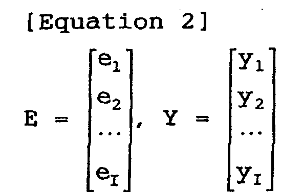 the following residual equation holds on the basis of
equation (7):
the following residual equation holds on the basis of
equation (7):
XW = Y + E
In this case, the tap coefficient wj for determining the
prediction value E[y] close to the true speech y of high
sound quality can be determined by minimizing the square
error:

Therefore, when the above-described square error
differentiated by the tap coefficient wj becomes 0, it
follows that the tap coefficient wj that satisfies the
following equation will be the optimum value for determining
the prediction value E[y] close to the true speech y of high
sound quality.
[Equation 4] e1 ∂e1 ∂wj + e2 ∂e2 ∂wj +···+eI ∂eI ∂wj = 0 (j = 1, 2, ···, J)
Accordingly, first, by differentiating equation (8)
with the tap coefficient wj, the following equations hold:
[Equation 5] ∂ei ∂w1 = xi1 , ∂ei ∂w2 = xi2 ,···, ∂ei ∂wJ = xiJ , (i = 1, 2, ···, I)
Equations (11) are obtained on the basis of equations
(9) and (10):

Furthermore, when the relationships among the student
data xij, the tap coefficient wj, the teacher data yi, and
the error ei in the residual equation of equation (8) are
taken into consideration, the following normalization
equations can be obtained on the basis of equations (11):
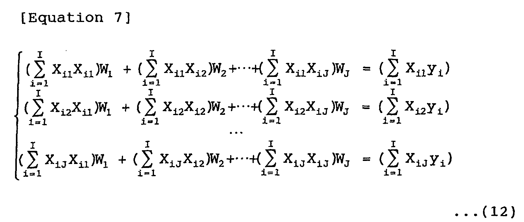
When the matrix (covariance matrix) A and a vector v
are defined on the basis of:
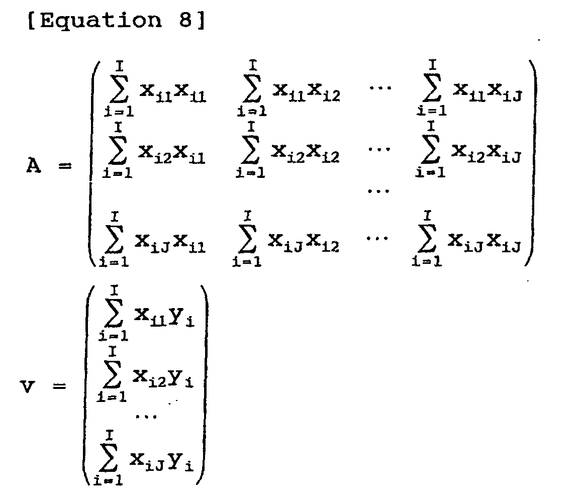 and when a vector W is defined as shown in equation 1, the
normalization equation shown in equations (12) can be
expressed by the following equation:
and when a vector W is defined as shown in equation 1, the
normalization equation shown in equations (12) can be
expressed by the following equation:
AW = v
Each normalization equation in equation (12) can be
formulated by the same number as the number J of the tap
coefficient wj to be determined by preparing the set of the
student data xij and the teacher data yi by a certain degree
of number. Therefore, solving equation (13) with respect to
the vector W (however, to solve equation (13), it is
required that the matrix A in equation (13) be regular)
enables the optimum tap coefficient (here, a tap coefficient
that minimizes the square error) wj to be determined. When
solving equation (13), for example, a sweeping-out method
(Gauss-Jordan's elimination method), etc., can be used.
The adaptation process determines, in the above-described
manner, the optimum tap coefficient wj in advance,
and the tap coefficient wj is used to determine, based on
equation (6), the predictive value E[y] close to the true
high-quality sound y.
For example, in a case where, as the teacher data, an
speech signal which is sampled at a high sampling frequency
or an speech signal to which many bits are assigned is used,
and as the student data, synthesized speech obtained in such
a way that the speech signal as the teacher data is thinned
or an speech signal which is requantized with a small number
of bits is coded by the CELP method and the coded result is
decoded is used, regarding the tap coefficient, when an
speech signal which is sampled at a high sampling frequency
or an speech signal to which many bits are assigned is to be
generated, high-quality sound in which the prediction error
statistically becomes a minimum is obtained. Therefore, in
this case, it is possible to obtain higher-quality
synthesized speech.
In the receiving section 114 of Fig. 4, the
classification and adaptation process such as that described
above decodes the synthesized speech obtained by decoding
code data by a CELP method into higher-quality sound.
More specifically, Fig. 5 shows an example of the
configuration of the receiving section 114 of Fig. 4.
Components in Fig. 5 corresponding to the case in Fig. 2 are
given the same reference numerals, and in the following,
descriptions thereof are omitted where appropriate.
Synthesized speech data for each subframe, which is
output from the speech synthesis filter 29, and the L code
among the L code, the G code, the I code, and the A code for
each subframe, which are output from the channel decoder 21,
are supplied to the tap generation sections 121 and 122.
The tap generation sections 121 and 122 extract data used as
a prediction tap used to predict the prediction value of
high-quality sound and data used as a class tap used for
classification from the synthesized speech data and the I
code supplied to the tap generation sections 121 and 122,
respectively. The prediction tap is supplied to a
prediction section 125, and the class tap is supplied to a
classification section 123.
The classification section 123 performs classification
on the basis of the class tap supplied from the tap
generation section 122, and supplies the class code as the
classification result to a coefficient memory 124.
Here, as a classification method in the classification
section 123, there is a method using, for example, a K-bit
ADRC (Adaptive Dynamic Range Coding) process.
Here, in the K-bit ADRC process, for example, a maximum
value MAX and a minimum value MIN of the data forming the
class tap are detected, and DR = MAX - MIN is assumed to be
a local dynamic range of a set. Based on this dynamic range
DR, each piece of data which forms the class tap is
requantized to K bits. That is, the minimum value MIN is
subtracted from each piece of data which forms the class tap,
and the subtracted value is divided (quantized) by DR/2K.
Then, a bit sequence in which the values of the K bits of
each piece of data which forms the class tap are arranged in
a predetermined order is output as an ADRC code.
When such a K-bit ADRC process is used for
classification, for example, a bit sequence in which the
values of the K-bit of each of data which forms a prediction
tap obtained as a result of the K-bit ADRC process are
arranged in a predetermined order is assumed to be a class
code.
In addition, for example, the classification can also
be performed by considering a class tap as a vector in which
each piece of data which forms the class tap is an element
and by performing vector quantization on the class tap as
the vector.
The coefficient memory 124 stores tap coefficients for
each class, obtained as a result of a learning process being
performed in the learning apparatus of Fig. 13, which will
be described later, and supplies to the prediction section
125 a tap coefficient stored at the address corresponding to
the class code output from the classification section 123.
The prediction section 125 obtains the prediction tap
output from the tap generation section 121 and the tap
coefficient output from the coefficient memory 124, and
performs the linear prediction computation shown in equation
(6) by using the prediction tap and the tap coefficient. As
a result, the prediction section 125 determines (the
prediction value of the) high-quality sound with respect to
the subject subframe of interest and supplies the value to
the D/A conversion section 30.
Next, referring to the flowchart in Fig. 6, a
description is given of a process of the receiving section
114 of Fig. 5.
The channel decoder 21 separates an L code, a G code,
an I code, and an A code from the code data supplied thereto,
and supplies the codes to the adaptive codebook storage
section 22, the gain decoder 23, the excitation codebook
storage section 24, and the filter coefficient decoder 25,
respectively. Furthermore, the L code is also supplied to
the tap generation sections 121 and 122.
Then, the adaptive codebook storage section 22, the
gain decoder 23, the excitation codebook storage section 24,
and arithmetic units 26 to 28 perform the same processes as
in the case of Fig. 2, and as a result, the L code, the G
code, and the I code are decoded into a residual signal e.
This residual signal is supplied to the speech synthesis
filter 29.
Furthermore, as described with reference to Fig. 2, the
filter coefficient decoder 25 decodes the A code supplied
thereto into a linear prediction coefficient and supplies it
to the speech synthesis filter 29. The speech synthesis
filter 29 performs speech synthesis by using the residual
signal from the arithmetic unit 28 and the linear prediction
coefficient from the filter coefficient decoder 25, and
supplies the resulting synthesized speech to the tap
generation sections 121 and 122.
The tap generation section 121 assumes the subframe of
the synthesized speech which is output in sequence by the
speech synthesis filter 29 to be a subject subframe in
sequence. In step S1, the tap generation section 121
generates a prediction tap from the synthesized speech of
the subject subframe and the I code of the subframe, which
will be described later, and supplies the prediction tap to
the prediction section 125. Furthermore, in step S1, for
example, the tap generation section 122 also generate a
class tap from the synthesized speech of the subject
subframe, and the I code of the subframe, which will be
described later, and supplies the class tap to the
classification section 123.
Then, the process proceeds to step S2, where the
classification section 123 performs classification on the
basis of the class tap supplied from the tap generation
section 122, and supplies the resulting class code to the
coefficient memory 124, and then the process proceeds to
step S3.
In step S3, the coefficient memory 124 reads a tap
coefficient from the address corresponding to the class code
supplied from the classification section 123, and supplies
the tap coefficient to the prediction section 125.
Then, the process proceeds to step S4, where the
prediction section 125 obtains the tap coefficient output
from the coefficient memory 124, and performs the sum-of-products
computation shown in equation (6) by using the tap
coefficient and the prediction tap from the tap generation
section 121, so that (the prediction value of) the high-quality
sound data of the subject subframe is obtained.
The processes of steps S1 to S4 are performed by using
each of the sample values of the synthesized speech data of
the subject subframe in sequence as subject data. That is,
since the synthesized speech data of the subframe is
composed of 40 samples, as described above, the processes of
steps S1 to S4 are performed for each of the synthesized
speech data for the 40 samples.
The high-quality sound obtained in the above-described
manner is supplied from the prediction section 125 via the
D/A conversion section 30 to a speaker 31, whereby high-quality
sound is output from the speaker 31.
After the process of step S4, the process proceeds to
step S5, where it is determined whether or not there are any
more subframes to be processed as subject subframes. When
it is determined that there is a subframe to be processed as
subject subframe, the process returns to step S1, where a
subframe to be used as the next subject subframe is newly
used as a subject subframe, and hereafter, the same
processes are repeated. When it is determined in step S5
that there is no subframe to be processed as a subject
subframe, the processing is terminated.
Next, referring to Fig. 7, a description is given of a
method of generating a prediction tap in the tap generation
section 121 of Fig. 5.
For example, as shown in Fig. 7, the tap generation
section 121 assumes each synthesized speech data (the
synthesized speech data output from the speech synthesis
filter 29) of the subframe to be subject data, and extracts,
as a prediction tap, the synthesized speech data of past N
samples (the synthesized speech data in the range shown in A
in Fig. 7) from the subject data and the past and future
synthesized speech data of a total of N samples (the
synthesized speech data in the range shown in B in Fig. 7)
with the subject data being the center.
Furthermore, the tap generation section 121 also
extracts, for example, as a prediction tap, the subframe
(subframe #3 in the embodiment of Fig. 7) at which the
subject data is positioned, that is, the I code located in
the subject subframe.
Therefore, in this case, the prediction tap is formed
of the synthesized speech data of N samples containing the
subject data, and the I code of the subject subframe.
Also, in the tap generation section 122, for example,
in the same manner as in the case of tap generation section
121, a class tap formed of synthesized speech data and the I
code is extracted.
However, the structure pattern of the prediction tap
and the class tap are not limited to the above-described
patterns. That is, as the prediction tap and the class tap,
in addition to extracting, from the subject data, the
synthesized speech data of all the N samples such as that
described above, it is possible to extract synthesized
speech data every other sample.
Furthermore, although in the above-described case, the
class tap and the prediction tap are formed in the same ways,
the class tap and the prediction tap can be formed in
different ways.
The prediction tap and the class tap can be formed only
from synthesized speech data. However, in the manner
described above, also, by forming the prediction tap and the
class tap by using the I code as information related to the
synthesized speech data in addition to the synthesized
speech data, it becomes possible to decode higher-quality
sound.
However, in the manner of the above-described case,
when only the I code located in the subframe where the
subject data is positioned (subject subframe) is contained
in the prediction tap and the class tap, a balance, so to
speak, between the synthesized speech data which forms the
prediction tap and the class tap, and the I code is not
achieved. For this reason, there is a risk that the sound-quality
improvement effect by the class classification and
adaptation process cannot be obtained sufficiently.
More specifically, for example, in Fig. 7, when the
synthesized speech data of past N samples from the subject
data (the synthesized speech data in the range shown in A in
Fig. 7) is to be contained in the prediction tap, the
synthesized speech data which is used as the prediction tap
contains not only the synthesized speech data of the subject
subframe, but also the synthesized speech data of the
subframe immediately before. Therefore, in this case, if
the I code located in the subject subframe is to be
contained in the prediction tap, unless the I code located
in the subframe immediately before is contained in the
prediction tap, there is a risk in that the relationship
between the synthesized speech data which forms the
prediction tap, and the I code does not become a balanced
one.
Therefore, the subframe of the I code from which the
prediction tap and the class tap are formed can be made
variable according to the position of the subject data in
the subject subframe.
More specifically, for example, in a case where the
synthesized speech data contained in the prediction tap
which is formed from the subject data extends up to the
subframe adjacent immediately before or after the subject
subframe (hereinafter referred to as an "adjacent subframe")
or in a case where the synthesized speech data extends up to
a position near the adjacent subframe, it is possible to
form the prediction tap so as to contain not only the I code
of the subject subframe, but also the I code of the adjacent
subframe. The class tap can also be formed in the same
manner.
In this manner, by forming the prediction tap and the
class tap so that the balance between the synthesized speech
data and the I code, which form the prediction tap and the
class tap, is achieved, it becomes possible to obtain a
sufficient sound-quality improvement effect due to a
classification and adaptation process.
Fig. 8 shows an example of the configuration of the tap
generation section 121 for forming the prediction tap so as
to be able to achieve a balance between the synthesized
speech data and the I code, which form the prediction tap,
by making the subframe of the I code which forms the
prediction tap variable according to the position of the
subject data in the subject subframe in the above-described
manner. The tap generation section 122 for forming a class
tap can also be formed similarly to that of Fig. 8.
The synthesized speech data output from the speech
synthesis filter 29 of Fig. 5 is supplied to a memory 41A,
and the memory 41A temporarily stores the synthesized speech
data supplied thereto. The memory 41A has at least a
storage capacity capable of storing the synthesized speech
data of N samples which form one prediction tap.
Furthermore, the memory 41A stores the latest sample of the
synthesized speech data supplied thereto in sequence in such
a manner as to overwrite on the oldest stored value.
Then, a data extraction circuit 42A extracts, from the
subject data, the synthesized speech data which forms the
prediction tap by reading it from the memory 41A, and
outputs the synthesized speech data to a combining circuit
43.
More specifically, when, for example, the latest
synthesized speech data stored in the memory 41A is assumed
to be subject data, the data extraction circuit 42A extracts
the synthesized speech data of past N samples from the
latest synthesized speech data by reading it from the memory
41A, and outputs the data to the combining circuit 43.
As shown in B in Fig. 7, when past and future
synthesized speech data of N samples with the subject data
as the center are to be used as prediction taps, the
synthesized speech data in the past by N/2 (decimal places
are, for example, raised to the next whole number) samples
from the latest synthesized speech data within the
synthesized speech data stored in the memory 41A may be
assumed to be subject data, and past and future synthesized
speech data of a total of N samples with the subject data
being the center may be read from the memory 41A.
Meanwhile, the I codes in subframe units, output from
the channel decoder 21 of Fig. 5, are supplied to a memory
41B, and the memory 41B temporarily stores the I code
supplied thereto. The memory 41B has at least a storage
capacity capable of storing I codes for an amount capable of
forming one prediction tap. Furthermore, similarly to the
memory 41A, the memory 41B stores the latest I code supplied
thereto in such a manner as to overwrite on the oldest
stored value.
Then, a data extraction circuit 42B extracts only the I
code of the subject subframe, or the I code of the subject
subframe and the I code of the subframe adjacent to the
subject subframe (adjacent subframe) by reading them from
the memory 41B according to the position of the synthesized
speech data which is assumed to be subject data by the data
extraction circuit 42A in the subject subframe, and outputs
them to the combining circuit 43.
The combining circuit 43 combines (merges) the
synthesized speech data from the data extraction circuit 42A
and the I code from the data extraction circuit 42B into one
set of data, and outputs it as the prediction tap.
In the tap generation section 121, when the prediction
tap is to be generated in the above-described manner, the
synthesized speech data which forms the prediction tap is
fixed at N samples. However, for the I code, there is a
case in which it is only the I code of the subject subframe,
and there is a case in which it is the I code of the subject
subframe and the I code of the subframe adjacent to the
subject subframe (adjacent subframe). Therefore, the number
of the I codes varies. This applies the same to the class
tap generated in the tap generation section 122.
For the prediction tap, even if the number of data
(number of taps) which forms it varies, no problem is posed
because the same number of the tap coefficients as the
number of prediction taps need only be learnt in the
learning apparatus of Fig. 13 (to be described later) and
the tap coefficients need only be stored in the coefficient
memory 124.
On the other hand, for the class tap, if the number of
taps which form the class tap varies, the number of all the
classes obtained by the class tap varies, presenting the
risk that the processing becomes complex. Therefore, it is
preferable that classification in which, even if the number
of taps of the class tap varies, the number of classes
obtained by the class tap does not vary be performed.
As a method of performing classification in which, even
if the number of taps of the class tap varies, the number of
classes obtained by the class tap does not vary, there is a
method in which, for example, the position of the subject
data in the subject subframe is taken into consideration.
More specifically, in this embodiment, the number of
taps of the class tap increases or decreases according to
the position of the subject data in the subject subframe.
For example, it is assumed that there are cases in which the
number of taps of the class tap is S and L which is greater
than S (> S), and when the number of taps is S, a class of n
bits is obtained, and when the number of taps is L, a class
code of n + m bits is obtained.
In this case, as the class code, n + m + 1 bits are
used, and, for example, 1 bit, such as the highest-order bit,
within the n + m + 1 bits is set to, for example, "0" and
"1" depending on the case in which the number of class taps
is S and L. As a result, even if the number of taps is
either S or L, classification in which the total number of
classes is 2n+m+1 becomes possible.
More specifically, when the number of class taps is L,
classification in which a class code of n + m bits is
obtained may be performed, and n + m + 1 bits such that "1"
as the highest-order bit indicating that the number of taps
is L is added to the class code of the n + m bits may be
assumed to be the final class code.
Furthermore, when the number of taps of the class tap
is S, classification in which a class code of n bits is
obtained may be performed, "0" of m bits as the high-order
bits may be added to the class code of the n bits so as to
be formed as n + m bits, and n + m + 1 bits such that "0",
as the highest-order bit, indicating that the number of
class taps is S is added to the n + m bits may be assumed to
be the final class code.
In the above-described manner, even if the number of
taps of the class tap is either S or L, classification in
which the total number of classes is 2n+m+1 becomes possible.
When the number of taps is S, the bits from the second bit
counting from the highest-order bit up to the (m+1)-th bit
always become "0".
Therefore, as described above, when classification in
which a class code of n + m + 1 bits is output is performed,
(a class code indicating) a class which is not used occurs,
that is, a useless class, so to speak, occurs.
Therefore, in order that occurrence of such a useless
class be prevented to make the total number of classes fixed,
classification can be performed by providing a weight to the
data which forms the class tap.
More specifically, for example, in a case where the
synthesized speech data of N samples which is past from the
subject data, shown in A in Fig. 7, is to be contained in a
class tap, and one or both of the I code of the subject
subframe (hereinafter referred to as a "subject subframe #n"
where appropriate) and the I code of subframe #n-1
immediately before are to be contained in the class tap
according to the position of the subject data in the subject
subframe, for example, weighting such as that shown in Fig.
9A is performed to the number of classes corresponding to
the I code of the subject subframe #n which forms the class
tap and the number of classes corresponding to the I code of
the subframe #n-1 immediately before, allowing the number of
classes to be fixed.
That is, Fig. 9A shows that classification is performed
in which the more to the right (future) of the subject
subframe #n the subject data is positioned, the more the
number of classes corresponding to the I code of subject
subframe #n is increased. Furthermore, Fig. 9A shows that
classification is performed in which the more to the right
of the subject subframe #n the subject data is positioned,
the more the number of classes corresponding to the I code
of subframe #n-1 immediately before is decreased. As a
result of weighting such as that shown in Fig. 9A being
performed, classification in which the overall number of
classes becomes fixed is performed.
Furthermore, for example, in a case where the past and
future synthesized speech data of a total of N samples,
shown in B in Fig. 7, with the subject data being the center
is to be contained in the class tap, and the I code of
subject subframe #n and one or both of the I codes of
subframe #n-1 immediately before and subframe #n+1
immediately after are to be contained in the class tap, for
example, weighting such as that shown in Fig. 9B is
performed to the number of classes corresponding to the I
code of the subject subframe #n which forms the class tap,
the number of classes corresponding to the I code of
subframe #n-1 immediately before, and the I code of the
number of classes corresponding to the I code of subframe
#n+1 immediately after, allowing the number of classes to be
fixed.
That is, Fig. 9B shows that classification in which the
more close to the center position of the subject subframe #n
the subject data is, the more the number of classes
corresponding to the I code of subject subframe #n is
increased. Furthermore, Fig. 9B shows that classification
in which the more to the left (in the past) of subject
subframe #n the subject data is positioned, the more the
number of classes corresponding to the I code of subframe
#n-1 immediately before the subject subframe #n is increased,
and the more to the right (in the future) of the subject
subframe #n the subject data is positioned, the more the
number of classes corresponding to the I code of subject
subframe #n+1 immediately after subject subframe #n is
increased. As a result of weighting such as that shown in
Fig. 9B being performed, classification in which the overall
number of classes becomes fixed is performed.
Next, Fig. 10 shows an example of weighting in a case
where classification in which the number of classes
corresponding to the I code becomes fixed at 512.
More specifically, Fig. 10A shows a specific example of
weighting shown in Fig. 9A in a case where one or both of
the I code of subject subframe #n and the I code of subframe
#n-1 immediately before are contained in the class tap
according to the position of the subject data in the subject
subframe.
Fig. 10B shows a specific example of weighting shown in
Fig. 9B in a case where the I code of subject subframe #n,
and one or both of the I code of subject subframe #n-1
immediately before and the I code of subframe #n+1
immediately after are contained in the class tap according
to the position the subject data in the subject subframe.
In Fig. 10A, the leftmost column shows the position of
the subject data in the subject subframe from the left end.
The second column from the left shows the number of classes
by the I code of the subframe immediately before the subject
subframe. The third column from the left shows the number
of classes by the I code of the subject subframe. The
rightmost column shows the number of classes by the I code
which forms the class tap (the number of classes by the I
code of the subject subframe and the I code of the subframe
immediately before).
Here, for example, as described above, since the
subframe is composed of 40 samples, the position of the
subject data in the subject subframe from the left end (the
leftmost column) takes a value in the range of 1 to 40.
Furthermore, for example, as described above, since the I
code is 9 bits long, there is a case in which the number of
classes becomes a maximum when the 9 bits are directly
assumed to be a class code. Therefore, the number of
classes by the I code (the second and third columns from the
left) takes a value of 29 (= 512) or lower.
Furthermore, as described above, when one I code is
directly used as a class code, the number of classes becomes
512 (29). Therefore, in Fig. 10A (the same applies in Fig.
10B, which will be described later), weighting is performed
to the number of classes by the I code of the subject
subframe and the number of classes by the I code of the
subframe immediately before so that the number of classes by
all the I codes which form the class tap (the number of
classes by the I code of the subject subframe and by the I
code of the subframe immediately before) becomes 512, that
is, the product of the number of classes by the I code of
the subject subframe and the number of classes by the I code
of the subframe immediately before becomes 512.
In Fig. 10A, as described in Fig. 9A, the more to the
right of subject subframe #n the subject data is positioned
(the more the value indicating the position of the subject
data is increased), the more the number of classes
corresponding to the I code of subject subframe #n is
increased and the number of classes corresponding to the I
code of subframe #n-1 immediately before subject subframe #n
is decreased.
In Fig. 10B, the leftmost column, the second column
from the left, the third column from the left, and the
rightmost column show the same contents as in the case of
Fig. 10A. The fourth column from the left shows the number
of classes by the I code of the subframe immediately after
the subject subframe.
In Fig. 10B. as described in Fig. 9B, the more away
from the center position of subject subframe #n the subject
data is (the more the value indicating the position of the
subject data is increased or decreased), the number of
classes corresponding to the I code of subject subframe #n
is decreased. Furthermore, the more to the left of subject
subframe #n the subject data is positioned, the more the
number of classes corresponding to the I code of subframe
#n-1 immediately before subject subframe #n is increased.
In addition, the more to the right of subject subframe #n
the subject data is positioned, the more the number of
classes corresponding to the I code of subframe #n+1
immediately after subject subframe #n is increased.
Fig. 11 shows an example of the configuration of the
classification section 123 of Fig. 5 for performing
classification involving weighting such as that described
above.
Here, it is assumed that the class tap is composed of,
for example, the synthesized speech data of N samples in the
past from the subject data, and the I codes of the subject
data and the subframe immediately before, shown in A in Fig.
7.
The class tap output from the tap generation section
122 (Fig. 5) is supplied to a synthesized speech-data
extraction section 51 and a code extraction section 53.
The synthesized speech-data extraction section 51 cuts
out (extracts), from a class tap supplied thereto,
synthesized speech data of a plurality of samples forming
the class tap, and supplies the synthesized speech data to
an ADRC circuit 52. The ADRC circuit 52 performs, for
example, a one-bit ADRC process on a plurality of items of
synthesized speech data (here, the synthesized speech data
of N samples) supplied from the synthesized speech-data
extraction section 51, and supplies a bit sequence, in which
one bit for a plurality of items of resulting synthesized
speech data is arranged in a predetermined order, to a
combining circuit 56.
Meanwhile, the code extraction section 53 cuts out
(extracts) the I code which forms the class tap from the
class tap supplied thereto. Furthermore, the code
extraction section 53 supplies the I code of the subject
subframe and the I code of the subframe immediately before
among the cutout I codes to degeneration section 54A and 54B,
respectively.
The degeneration section 54A stores a degeneration
table created by a table creation process (to be described
later). In the manner described in Figs. 9 and 10, by using
the degeneration table, the degeneration section 54A
degenerates (decreases) the number of classes represented by
the I code of the subject subframe according to the position
of the subject data in the subject subframe, and supplies
the number of classes to a synthesis circuit 55.
That is, when the position of the subject data in the
subject subframe is one of the first to the fourth from the
left, the degeneration section 54A performs a degeneration
process so that, for example, as shown in Fig. 10A, the
number of classes of 512 represented by the I code of the
subject subframe is made to be 512, that is, an I code of 9
bits of the subject subframe is not particularly processed
and is directly output.
Furthermore, when the position of the subject data in
the subject subframe is one of the fifth to the eighth from
the left, for example, as shown in Fig. 10A, the
degeneration section 54A performs a degeneration process so
that the number of classes of 512 indicated by the I code of
the subject subframe becomes 256, that is, the I code of 9
bits of the subject subframe is converted into a code
indicated by 8 bits by using a degeneration table, and this
code is output.
Furthermore, when the position of the subject data in
the subject subframe is one of the ninth to the twelfth from
the left, for example, as shown in Fig. 10A, a degeneration
section 54A performs a degeneration process so that the
number of classes of 512 indicated by the I code of the
subject subframe becomes 128, that is, the I code of 9 bits
of the subject subframe is converted into a code indicated
by 7 bits by using the degeneration table, and code this is
output.
Hereafter, in a similar manner, the degeneration
section 54A degenerates the number of classes indicated by
the I code of the subject subframe as shown in the second
column from the left of Fig. 10A according to the position
of the subject data in the subject subframe, and outputs the
number of classes to a combining circuit 55.
The degeneration section 54B also stores a degeneration
table similarly to the degeneration section 54A. By using
the degeneration table, the degeneration section 54B
degenerates the number of classes indicated by the I code of
the subframe as shown in the third column from the left of
Fig. 10A according to the position of the subject data in
the subject subframe, and outputs the number of classes to
the combining circuit 55.
The combining circuit 55 combines the I code of the
subject subframe in which the number of classes is
degenerated as appropriate, from the degeneration section
54A, and the I code of the subframe immediately before the
subject subframe, in which the number of classes is
degenerated as appropriate, from the degeneration circuit
54B, into one bit sequence, and supplies the bit sequence to
a combining circuit 56.
The combining circuit 56 combines the bit sequence
output from the ADRC circuit 52 and the bit sequence output
from the combining circuit 55 into one bit sequence, and
supplies the bit sequence as a class code.
Next, referring to the flowchart in Fig. 12, a
description is given of a table creation process of creating
a degeneration table used in the degeneration sections 54A
and 54B of Fig. 11.
In the degeneration table creation process, initially,
in step S11, a number of classes M after degeneration is set.
Here, for simplicity of description, for example, M is set
as a value which is raised to a power of 2. Furthermore,
here, since a degeneration table for degenerating the number
of classes represented by the I code of 9 bits is created, M
is set to a value of 512 which is the maximum number of
classes indicated by an I code of 9 bits or lower.
Thereafter, the process proceeds to step S12, where a
variable c indicating the class code after degeneration is
set to "0", and the process proceeds to step S13. In step
S13, all the I codes (first, all the numbers indicated by
the I code of 9 bits) are set as object I codes for the
object of processing, and the process proceeds to step S14.
In step S14, one of the object I codes is selected as a
subject I code, and the process proceeds to step S15.
In step S15, the square error of a waveform represented
by the I code (waveform of an excitation signal) and each of
waveforms represented by all the object codes is calculated.
More specifically, as described above, the I code
corresponds to a predetermined excitation signal. In step
S15, the sum of the square errors of each sample value of
the waveform of the excitation signal represented by the
subject I code and the corresponding sample value of the
waveform of the excitation signal represented by the object
I codes is determined. In step S15, such a sum of square
error for the subject I codes is determined by using all
the object I codes as objects.
Thereafter, the process proceeds to step S16, where the
object I code at which the sum of the square errors for the
subject I code is minimized (hereinafter referred to as a
"least-square error I code" where appropriate) is detected,
and the subject I code and the least-square error I code are
made to correspond to the code represented by the variable c.
That is, as a result, the subject I code, and the object I
code representing the waveform which most resembles the
waveform represented by the subject I code (the least-square
error I code) among the object I codes are degenerated into
the same class c.
After the process of step S16, the process proceeds to
step S17, where, for example, an average value of each
sample value of the waveform represented by the subject I
code and the corresponding sample value of the waveform
represented by the least-square error I code is determined,
and the waveform by the average value is, as the waveform of
the excitation signal represented by the variable c, made to
correspond to the variable c.
Then, the process proceeds to step S18, where the
subject I code and the least-square error I code are
excluded from the object I codes. Then, the process
proceeds to step S19, where the variable c is incremented by
1, and the process proceeds to step S20.
In step S20, it is determined whether or not there is
an I code for an object I code. When it is determined that
there is an I code for an object I code, the process returns
to step S14, where a new subject I code is selected from the
I code for an object I code, and hereafter, the same
processes are repeated.
When it is determined in step S20 that there is no I
code for an object I code, that is, when the I code which is
made to be an object I code in the previous step S13 is made
to correspond to variables c in a number of 1/2 of the total
number of the I codes, the process proceeds to step S21,
where it is determined whether or not the variable c is
equal to the number of classes M after degeneration.
When it is determined in step S21 that the variable c
is not equal to the number of classes M after degeneration,
that is, when the number of classes represented by the I
code of 9 bits is not yet degenerated into the M classes,
the process proceeds to step S22, where each value
represented by the variable c is newly assumed to be an I
code. Then, the process returns to step S12, and hereafter,
by using the new I code as an object, the same processes are
repeated.
Regarding the new I code, by using the waveform
determined in step S17 as a waveform of the excitation
signal indicated by the new I code, the square error in step
S15 is calculated.
On the other hand, when it is determined in step S21
that the variable c is equal to the number of classes M
after degeneration, that is, when the number of classes
represented by the I code of 9 bits is degenerated into the
M classes, the process proceeds to step S23, where a
correspondence table between each value of the variables c
and the I code of 9 bits corresponding to the value is
created, the correspondence table is output as a
degeneration table, and the processing is then terminated.
In the degeneration sections 54A and 54B of Fig. 11,
the I code of the 9 bits supplied thereto is degenerated as
a result of being converted into a variable c which is made
to correspond to the I code of the 9 bits in the
degeneration table created in the above-described manner.
In addition, for example, the degeneration of the
number of classes by the I code of the 9 bits can also be
performed by simply deleting the low-order bits of the I
code. However, it is preferable that the degeneration of
the number of classes be performed in such a manner that the
resembling classes are collected. Therefore, instead of
simply deleting the low-order bits of the I code, as
described in Fig. 12, the I codes indicating the excitation
signal having resembling waveforms are preferably assigned
to the same class.
Next, Fig. 13 shows an example of the configuration of
an embodiment of a learning apparatus for performing a
process of learning tap coefficients stored in the
coefficient memory 124 of Fig. 5.
A series of components from a microphone 201 to a code
determination section 215 are formed similarly to the series
of components from the microphone 1 to the code
determination section 15 of Fig. 1, respectively. A
learning speech signal of high quality is input to the
microphone 1, and therefore, in the microphone 201 to the
code determination section 215, the same processes as in the
case of Fig. 1 are performed on the learning speech signal.
However, the code determination section 215 outputs
only the L codes which form the prediction tap and the class
tap in this embodiment among the L code, the G code, the I
code, and the A code.
Then, the synthesized speech output by the speech
synthesis filter 206 when it is determined in the least-square
error determination section 208 that the square error
reaches a minimum is supplied to tap generation sections 131
and 132. Furthermore, an I code which is output by the code
determination section 215 when the code determination
section 215 receives a determination signal from the least-square
error determination section 208 is also supplied to
the tap generation sections 131 and 132. Furthermore,
speech output by an A/D conversion section 202 is supplied
as teacher data to a normalization equation addition circuit
134.
The generation section 131 generates the same
prediction tap as in the case of the tap generation section
121 of Fig. 5 from the synthesized speech data output from
the speech synthesis filter 206 and the I code output from
the code determination section 215, and supplies the
prediction tap as student data to the normalization equation
addition circuit 134.
The tap generation section 132 also generates the same
class tap as in the case of the tap generation section 122
of Fig. 5 from the synthesized speech data output from the
speech synthesis filter 206 and the I code output from the
code determination section 215, and supplies the class tap
to a classification section 133.
The classification section 133 performs the same
classification as in the case of the classification section
123 of Fig. 5 on the basis of the class tap from the tap
generation section 132, and supplies the resulting class
code to the normalization equation addition circuit 134.
The normalization equation addition circuit 134
receives speech from the A/D conversion section 202 as
teacher data, and receives the prediction tap from the
generation section 131 as student data, and performs
addition for each class code from the classification section
133 by using the teacher data and the student data as
objects.
More specifically, the normalization equation addition
circuit 134 performs, for each class corresponding to the
class code supplied from the classification section 133,
multiplication of the student data (xinxim) which is each
component in the matrix A of equation (13), and a
computation equivalent to summation (Σ), by using the
prediction tap (student data).
Furthermore, the normalization equation addition
circuit 134 also performs, for each class corresponding to
the class code supplied from the classification section 133,
multiplication of the student data and the teacher data
(xinyi) which is each component in the vector v of equation
(13), and a computation equivalent to summation (Σ), by
using the student data and the teacher data.
The normalization equation addition circuit 134
performs the above-described addition by using all the
subframes of the speech for learning supplied thereto as the
subject subframes. As a result, a normalization equation
shown in equation (13) is formulated for each class.
A tap coefficient determination circuit 135 determines
the tap coefficient for each class by solving the
normalization equation generated for each class in the
normalization equation addition circuit 134, and supplies
the tap coefficient to the address, corresponding to each
class, of the coefficient memory 136.
Depending on the speech signal prepared as a learning
speech signal, in the normalization equation addition
circuit 134, a class may occur at which normalization
equations of a number required to determine the tap
coefficient are not obtained. For such a class, the tap
coefficient determination circuit 135 outputs, for example,
a default tap coefficient.
The coefficient memory 136 stores the tap coefficient
for each class supplied from the tap coefficient
determination circuit 135 at an address corresponding to
that class.
Next, referring to the flowchart in Fig. 14, a
description is given of a learning process of determining a
tap coefficient for decoding high-quality sound, performed
in the learning apparatus of Fig. 13.
More specifically, a learning speech signal is supplied
to the learning apparatus. In step S31, teacher data and
student data are generated from the learning speech signal.
More specifically, the learning speech signal is input
to the microphone 201, and the microphone 201 to the code
determination section 215 perform the same processes as in
the case of the microphone 1 to the code determination
section 15 in Fig. 1, respectively.
As a result, the speech of the digital signal obtained
by the A/D conversion section 202 is supplied as teacher
data to the normalization equation addition circuit 134.
Furthermore, when it is determined in the least-square error
determination section 208 that the square error reaches a
minimum, the synthesized speech data output from the speech
synthesis filter 206 is supplied as student data to the tap
generation sections 131 and 132. Furthermore, the I code
output from the code determination section 215 when it is
determined in the least-square error determination section
208 that the square error reaches a minimum is also supplied
as student data to the tap generation sections 131 and 132.
Thereafter, the process proceeds to step S32, where the
tap generation section 131 assumes, as the subject subframe,
the subframe of the synthesized speech supplied as student
data from the speech synthesis filter 206, and further
assumes the synthesized speech data of that subject subframe
in sequence as the subject data, generates, with respect to
each of subject data, a prediction tap similarly to the case
in the tap generation section 121 of Fig. 5 from the
synthesized speech data from the speech synthesis filter 206
and the L code from the code determination section 215, and
supplies the prediction tap to the normalization equation
addition circuit 134. Furthermore, in step S32, the tap
generation section 132 also generates a class tap from the
synthesized speech data similarly to the case in the tap
generation section 122 of Fig. 5, and supplies the class tap
to the classification section 133.
After the process of step S32, the process proceeds to
step S33, where the classification section 133 performs
classification on the basis of the class tap from the tap
generation section 132, and supplies the resulting class
code to the normalization equation addition circuit 134.
Then, the process proceeds to step S34, where the
normalization equation addition circuit 134 performs
addition of the matrix A and the vector v of equation (13),
such as that described above, for each class code with
respect to the subject data, from the classification section
133, by using as objects speech within the learning speech
as teacher data from the A/D conversion section 202, which
corresponds to the subject data, and the prediction tap (the
prediction tap generated from the subject data) as the
student data from the tap generation section 132. Then, the
process proceeds to step S35.
In step S35, it is determined whether or not there are
any more subframes to be processed as subject subframes.
When it is determined in step S35 that there is still a
subframe to be processed as a subject subframe, the process
returns to step S31, where the next subframe is newly
assumed to be a subject subframe, and hereafter, the same
processes are repeated.
Furthermore, when it is determined in step S35 that
there is no subframe to be processed as a subject subframe,
the process proceeds to step S36, where the tap coefficient
determination circuit 135 solves the normalization equation
generated for each class in the normalization equation
addition circuit 134 in order to determine the tap
coefficient for each class, supplies the tap coefficient to
the address, corresponding to each class, of the coefficient
memory 136, whereby the tap coefficient is stored, and the
processing is then terminated.
In the above-described manner, the tap coefficient for
each class, stored in the coefficient memory 136, is stored
in the coefficient memory 124 of Fig. 5.
In the manner described above, since the tap
coefficient stored in the coefficient memory 124 of Fig. 5
is determined in such a way that learning is performed so
that the prediction error (square error) of a speech
prediction value of high-quality speech, obtained by
performing a linear prediction computation, statistically
becomes a minimum, the speech output by the prediction
section 125 of Fig. 5 becomes high-sound quality.
For example, in the embodiment of Figs. 5 and 13, in
addition to synthesized speech data output from the speech
synthesis filter 206, an I code (which becomes coded data)
contained in coded data is contained in the prediction tap
and the class tap. However, as indicated by the dotted
lines in Figs. 5 and 13, the prediction tap and the class
tap can be formed so as to contain, instead of the I code or
in addition to the I code, one or more of the I code, the L
code, the G code, the A code, a linear prediction
coefficient αp obtained from the A code, a gain β or γ
obtained from the G code, and other information (for example,
an residual signal e, l or n for obtaining the residual
signal e, further, l/β, n/γ, etc.) obtained from the L code,
the G code, the I code, or the A code. Furthermore, in the
CELP method, there is a case in which list interpolation
bits, frame energy, etc., are contained in code data as
coded data. In this case, the prediction tap and the class
tap can also be formed so as to use soft interpolation bits
and frame energy.
Next, the above-described series of processes can be
performed by hardware and can also be performed by software.
In a case where the series of processes are to be performed
by software, programs which form the software are installed
into a general-purpose computer, etc.
Therefore, Fig. 15 shows an example of the
configuration of an embodiment of a computer into which
programs for executing the above-described series of
processes are executed are installed.
The programs can be prerecorded in a hard disk 305 and
a ROM 303 as a recording medium built into the computer.
Alternatively, the programs may be temporarily or
permanently stored (recorded) in a removable recording
medium 311, such as a floppy disk, a CD-ROM (Compact Disc
Read Only Memory), an MO (Magneto optical) disk, a DVD
(Digital Versatile Disc), a magnetic disk, or a
semiconductor memory. Such a removable recording medium 311
may be provided as what is commonly called packaged software.
In addition to being installed into a computer from the
removable recording medium 311 such as that described above,
programs may be transferred in a wireless manner from a
download site via an artificial satellite for digital
satellite broadcasting or may be transferred by wire to a
computer via a network, such as a LAN (Local Area Network)
or the Internet, and in the computer, the programs which are
transferred in such a manner are received by a communication
section 308 and can be installed into the hard disk 305
contained therein.
The computer has a CPU (Central Processing Unit) 302
contained therein. An input/output interface 310 is
connected to the CPU 302 via a bus 301. When a command is
input as a result of a user operating an input section 307
formed of a keyboard, a mouse, a microphone, etc., via the
input/output interface 310, the CPU 302 executes a program
stored in the ROM (Read Only Memory) 303 in accordance with
the command. Alternatively, the CPU 302 loads a program
stored in the hard disk 305, a program which is transferred
from a satellite or a network, which is received by the
communication section 308, and which is installed into the
hard disk 305, or a program which is read from the removable
recording medium 311 loaded into a drive 309 and which is
installed into the hard disk 305, to a RAM (Random Access
Memory) 304, and executes the program. As a result, the CPU
302 performs processing in accordance with the above-described
flowcharts or processing performed according to
the constructions in the above-described block diagrams.
Then, the CPU 302 outputs the processing result, for example,
from an output section 306 formed of an LCD (Liquid Crystal
Display), a speaker, etc., via the input/output interface
310, as required, or transmits the processing result from
the communication section 308, and furthermore, records the
processing result in the hard disk 305.
Here, in this specification, processing steps which
describe a program for causing a computer to perform various
types of processing need not necessarily perform processing
in a time series along the described sequence as a flowchart
and contain processing performed in parallel or individually
(for example, parallel processing or object-oriented
processing) as well.
Furthermore, a program may be such that it is processed
by one computer or may be such that it is processed in a
distributed manner by plural computers. In addition, a
program may be such that it is transferred to a remote
computer and is executed thereby.
Although in this embodiment, no particular mention is
made as to what kinds of learning speech signals are used as
learning speech signals, in addition to speech produced by a
human being, for example, a musical piece (music), etc., can
be employed as learning speech signals. According to the
learning apparatus such as that described above, when
reproduced human speech is used as a learning speech signal,
a tap coefficient such as that which improves the sound
quality of human speech is obtained. When a musical piece
is used, a tap coefficient such as that which improves the
sound quality of the musical piece will be obtained.
Although tap coefficients are stored in advance in the
coefficient memory 124, etc., in the mobile phone 101, the
tap coefficients to be stored in the coefficient memory 124,
etc., can be downloaded from the base station 102 (or the
exchange 103) of Fig. 3, a WWW (World Wide Web) server (not
shown), etc. That is, as described above, tap coefficients
suitable for certain kinds of speech signals, such as for
human speech production or for a musical piece, can be
obtained through learning. Furthermore, depending on
teacher data and student data used for learning, tap
coefficients by which a difference occurs in the sound
quality of synthesized speech can be obtained. Therefore,
such various kinds of tap coefficients can be stored in the
base station 102, etc., so that a user is made to download
tap coefficients desired by the user. Such a downloading
service of tap coefficients can be performed free or for a
charge. Furthermore, when downloading service of tap
coefficients is performed for a charge, the cost for
downloading the tap coefficients can be charged, for example,
together with the charge for telephone calls of the mobile
phone 101.
Furthermore, the coefficient memory 124, etc., can be
formed by a removable memory card which can be loaded into
and removed from the mobile phone 101, etc. In this case,
if different memory cards in which various types of tap
coefficients, such as those described above, are stored are
provided, it becomes possible for the user to load a memory
card in which desired tap coefficients are stored into the
mobile phone 101 and to use it depending on the situation.
In addition, the present invention can be widely
applied to a case in which, for example, synthesized speech
is produced from codes obtained as a result of coding by a
CELP method such as VSELP (Vector Sum Excited Linear
Prediction), PSI-CELP (Pitch Synchronous Innovation CELP),
or CS-ACELP (Conjugate Structure Algebraic CELP).
Furthermore, the present invention is not limited to
the case where synthesized speech is decoded from codes
obtained as a result of coding by a CELP method, and can be
widely applied to a case in which the original data is
decoded from coded data having information (decoding
information) used for decoding in predetermined units. That
is, the present invention can also be applied to coded data
such that, for example, an image is coded by a JPEG (Joint
Photographic Experts Group) method having a DCT (Discrete
Cosine Transform) coefficient in predetermined block units.
Furthermore, although in this embodiment, prediction
values of a residual signal and a linear prediction
coefficient are determined by linear first-order prediction
computation using tap coefficients, additionally, these
prediction values can also be determined by high-order
prediction computation of a second or higher order.
For example, in Japanese Unexamined Patent Application
Publication No. 8-202399, a method in which the sound
quality of synthesized speech is improved by causing the
synthesized speech to pass through a high-frequency
accentuation filter is disclosed. However, the present
invention differs from the invention described in Japanese
Unexamined Patent Application Publication No. 8-202399 in
that a tap coefficient is obtained through learning, a tap
coefficient used for prediction calculation is adaptively
determined according to classification results, and further,
the prediction tap, etc. is generated not only from
synthesized speech, but is also generated from an I code,
etc., contained in coded data.
According to the data processing apparatus, the data
processing method, the program, and the recording medium of
the present invention, a tap used for a predetermined
process is generated by extracting decoded data in a
predetermined positional relationship with subject data of
interest within the decoded data such that coded data is
decoded and by extracting decoding information in
predetermined units according to a position of the subject
data in predetermined units, and the predetermined process
is performed by using the tap. Therefore, for example, it
becomes possible to obtain high-quality decoded data.
According to the data processing apparatus, the data
processing method, the program, and the recording medium of
the present invention, decoded data as student data serving
as a student is generated by coding teacher data serving as
a teacher into coded data having decoding information in
predetermined units and by decoding the coded data.
Furthermore, a prediction tap used to predict teacher data
is generated by extracting decoded data in a predetermined
positional relationship with subject data of interest within
the decoded data as the student data and by extracting the
decoding information in predetermined units according to a
position of the subject data in predetermined units. Then,
learning is performed so that a prediction error of the
prediction value of the teacher data obtained by performing
a predetermined prediction computation by using the
prediction tap and the tap coefficient statistically becomes
a minimum, and the tap coefficient is determined. Therefore,
it becomes possible to obtain a tap coefficient for decoding
high-quality decoded data from the coded data.
Claims (26)
- A data processing apparatus for processing coded data having decoding information used for decoding in predetermined units, said data processing apparatus comprising:tap generation means for generating a tap used for a predetermined process by extracting said decoded data in a predetermined positional relationship with subject data of interest within the decoded data such that said coded data is decoded and by extracting said decoding information in predetermined units according to the position of said subject data in said predetermined units; andprocessing means for performing a predetermined process by using said tap.
- A data processing apparatus according to Claim 1, further comprising tap coefficient obtaining means for obtaining a tap coefficient determined by performing learning,
wherein said tap generation means generates a prediction tap for performing a predetermined prediction computation with said tap coefficient, and
said processing means determines a prediction value corresponding to teacher data serving as a teacher in said learning by performing a predetermined prediction computation by using said prediction tap and said tap coefficient. - A data processing apparatus according to Claim 2, wherein said processing means determines said prediction value by performing a linear first-order prediction computation by using said prediction tap and said class tap.
- A data processing apparatus according to Claim 1, wherein said tap generation means generates a class tap used to perform classification for classifying said subject data, and
said processing means performs classification on said subject data on the basis of said class tap. - A data processing apparatus according to Claim 4, wherein said processing means performs classification by providing a weight to said decoding information which forms said class tap in predetermined units.
- A data processing apparatus according to Claim 5, wherein said processing means performs classification by providing a weight to said decoding information in predetermined units according to a position of said subject data in said predetermined units.
- A data processing apparatus according to Claim 5, wherein said processing means performs classification by providing a weight such that the number of all classes obtained by said classification becomes fixed on said decoding information in predetermined units.
- A data processing apparatus according to Claim 1, wherein said tap generation means generates a prediction tap for performing predetermined prediction computation with a tap coefficient determined by performing learning, and generates a class tap used for classification for classifying said subject data, and
said processing means performs classification on said subject data on the basis of said class tap, and performs a predetermined prediction computation by using said tap coefficient corresponding to the class obtained as a result of the classification and said prediction tap, thereby determining a prediction value corresponding to the teacher data serving as a teacher in said learning. - A data processing apparatus according to Claim 1, wherein said tap generation means extracts said decoding data at a position near said subject data or said decoding information in predetermined units.
- A data processing apparatus according to Claim 1, wherein said coded data is such that speech is coded.
- A data processing apparatus according to Claim 10, wherein said coded data is such that speech is coded by a CELP (Code Excited Linear coding) method.
- A data processing method for processing coded data having decoding information used for decoding in predetermined units, said data processing method comprising:a tap generation step of generating a tap used for a predetermined process by extracting said decoded data in a predetermined positional relationship with subject data of interest within the decoded data such that said coded data is decoded and by extracting said decoding information in predetermined units according to the position of said subject data in said predetermined units; anda processing step of performing a predetermined process by using said tap.
- A program for causing a computer to process coded data having decoding information used for decoding in predetermined units, said program comprising:a tap generation step of generating a tap used for a predetermined process by extracting said decoded data in a predetermined positional relationship with subject data of interest within the decoded data such that said coded data is decoded and by extracting said decoding information in predetermined units according to the position of said subject data in said predetermined units; anda processing step of performing a predetermined process by using said tap.
- A recording medium having recorded thereon a program for causing a computer to process coded data having decoding information used for decoding in predetermined units, said program comprising:a tap generation step of generating a tap used for a predetermined process by extracting said decoded data in a predetermined positional relationship with subject data of interest within the decoded data such that said coded data is decoded and by extracting said decoding information in predetermined units according to the position of said subject data in said predetermined units; anda processing step of performing a predetermined process by using said tap.
- A data processing apparatus for learning a predetermined tap coefficient used to process coded data having decoding information used for decoding in predetermined units, said data processing apparatus comprising:student data generation means for generating decoded data as student data serving as a student by coding teacher serving as a teacher into said coded data having decoding information in predetermined units and by decoding the coded data;prediction tap generation means for generating a prediction tap used to predict teacher data by extracting said decoded data in a predetermined positional relationship with subject data of interest within said decoded data as the student data and by extracting said decoding information in said predetermined units according to a position of said subject data in said predetermined units; andlearning means for performing learning so that a prediction error of the prediction value of said teacher data obtained by performing a predetermined prediction computation by using said prediction tap and said tap coefficient statistically becomes a minimum, and for determining said tap coefficient.
- A data processing apparatus according to Claim 15, wherein said learning means performs learning so that a prediction error of the prediction value of said teacher data obtained by performing a linear first-order prediction computation by using said prediction tap and said tap coefficient statistically becomes a minimum.
- A data processing apparatus according to Claim 15, further comprising:wherein said learning means determines said tap coefficient for each class obtained as a result of classification by said classification means.class tap generation means for generating a class tap used for classification for classifying said subject data by extracting said decoded data in a predetermined positional relationship with said subject data and by extracting said decoding information in predetermined units according to a position of said subject data in said predetermined unit; andclassification means for performing classification on said subject data on the basis of said class tap,
- A data processing apparatus according to Claim 17, wherein said classification means performs classification by providing a weight to decoding information which forms said class tap in said predetermined units.
- A data processing apparatus according to Claim 18, wherein said classification means performs classification by providing a weight to said decoding information in predetermined units according to a position of said subject data in said predetermined unit.
- A data processing apparatus according to Claim 18, wherein said classification means performs classification by providing a weight such that the number of all classes obtained by said classification becomes fixed to said decoding information in predetermined units.
- A data processing apparatus according to Claim 17, wherein said prediction tap generation means or said class tap generation means extracts said decoded data at a position near said subject data or said decoding information in predetermined units.
- A data processing apparatus according to Claim 15, wherein said teacher data is speech data.
- A data processing apparatus according to Claim 22, wherein student data generation means codes speech data as said teacher data by a CELP (Code Excited Linear coding) method.
- A data processing method for learning a predetermined tap coefficient used to process coded data having decoding information used for decoding in predetermined units, said data processing method comprising:a student data generation step of generating decoded data as student data serving as a student by coding teacher serving as a teacher into coded data having said decoding information in predetermined units and by decoding the coded data;a prediction tap generation step of generating a prediction tap used to predict teacher data by extracting said decoded data in a predetermined positional relationship with subject data of interest within said decoded data as the student data and by extracting said decoding information in said predetermined units according to a position of said subject data in said predetermined units; anda learning step of performing learning so that a prediction error of the prediction value of said teacher data obtained by performing a predetermined prediction computation by using said prediction tap and said tap coefficient statistically becomes a minimum, and for determining said tap coefficient.
- A program for learning a predetermined tap coefficient used to process coded data having decoding information used for decoding in predetermined units, said program comprising:a student data generation step of generating decoded data as student data serving as a student by coding teacher serving as a teacher into coded data having said decoding information in predetermined units and by decoding the coded data;a prediction tap generation step of generating a prediction tap used to predict teacher data by extracting said decoded data in a predetermined positional relationship with subject data of interest within said decoded data as the student data and by extracting said decoding information in said predetermined units according to a position of said subject data in said predetermined units; anda learning step of performing learning so that a prediction error of the prediction value of said teacher data, obtained by performing a predetermined prediction computation by using said prediction tap and said tap coefficient statistically becomes a minimum, and for determining said tap coefficient.
- A recording medium having recorded thereon a program for learning a predetermined tap coefficient used to process coded data having decoding information used for decoding in predetermined units, said program comprising:a student data generation step of generating decoded data as student data serving as a student by coding teacher serving as a teacher into coded data having said decoding information in predetermined units and by decoding the coded data;a prediction tap generation step of generating a prediction tap used to predict teacher data by extracting said decoded data in a predetermined positional relationship with subject data of interest within said decoded data as the student data and by extracting said decoding information in said predetermined units according to a position of said subject data in said predetermined units; anda learning step of performing learning so that a prediction error of the prediction value of said teacher data obtained by performing a predetermined prediction computation by using said prediction tap and said tap coefficient statistically becomes a minimum, and for determining said tap coefficient.
Applications Claiming Priority (3)
| Application Number | Priority Date | Filing Date | Title |
|---|---|---|---|
| JP2001016868A JP4857467B2 (en) | 2001-01-25 | 2001-01-25 | Data processing apparatus, data processing method, program, and recording medium |
| JP2001019868 | 2001-01-25 | ||
| PCT/JP2002/000489 WO2002059876A1 (en) | 2001-01-25 | 2002-01-24 | Data processing apparatus |
Publications (2)
| Publication Number | Publication Date |
|---|---|
| EP1282114A1 true EP1282114A1 (en) | 2003-02-05 |
| EP1282114A4 EP1282114A4 (en) | 2005-08-10 |
Family
ID=18883163
Family Applications (1)
| Application Number | Title | Priority Date | Filing Date |
|---|---|---|---|
| EP02710340A Withdrawn EP1282114A4 (en) | 2001-01-25 | 2002-01-24 | DATA PROCESSING APPARATUS |
Country Status (6)
| Country | Link |
|---|---|
| US (1) | US7467083B2 (en) |
| EP (1) | EP1282114A4 (en) |
| JP (1) | JP4857467B2 (en) |
| KR (1) | KR100875783B1 (en) |
| CN (1) | CN1215460C (en) |
| WO (1) | WO2002059876A1 (en) |
Cited By (1)
| Publication number | Priority date | Publication date | Assignee | Title |
|---|---|---|---|---|
| CN101604526B (en) * | 2009-07-07 | 2011-11-16 | 武汉大学 | Weight-based system and method for calculating audio frequency attention |
Families Citing this family (5)
| Publication number | Priority date | Publication date | Assignee | Title |
|---|---|---|---|---|
| EP1944760B1 (en) * | 2000-08-09 | 2009-09-23 | Sony Corporation | Voice data processing device and processing method |
| US8441966B2 (en) | 2010-03-31 | 2013-05-14 | Ubidyne Inc. | Active antenna array and method for calibration of receive paths in said array |
| US8311166B2 (en) * | 2010-03-31 | 2012-11-13 | Ubidyne, Inc. | Active antenna array and method for calibration of the active antenna array |
| US8340612B2 (en) | 2010-03-31 | 2012-12-25 | Ubidyne, Inc. | Active antenna array and method for calibration of the active antenna array |
| FR3013496A1 (en) * | 2013-11-15 | 2015-05-22 | Orange | TRANSITION FROM TRANSFORMED CODING / DECODING TO PREDICTIVE CODING / DECODING |
Family Cites Families (22)
| Publication number | Priority date | Publication date | Assignee | Title |
|---|---|---|---|---|
| JPS6111800A (en) * | 1984-06-27 | 1986-01-20 | 日本電気株式会社 | Residual excitation type vocoder |
| JPS63214032A (en) | 1987-03-02 | 1988-09-06 | Fujitsu Ltd | Coding transmitter |
| US4868867A (en) * | 1987-04-06 | 1989-09-19 | Voicecraft Inc. | Vector excitation speech or audio coder for transmission or storage |
| JPH01205199A (en) | 1988-02-12 | 1989-08-17 | Nec Corp | Sound encoding system |
| US5359696A (en) * | 1988-06-28 | 1994-10-25 | Motorola Inc. | Digital speech coder having improved sub-sample resolution long-term predictor |
| SG47028A1 (en) | 1989-09-01 | 1998-03-20 | Motorola Inc | Digital speech coder having improved sub-sample resolution long-term predictor |
| JP3102015B2 (en) | 1990-05-28 | 2000-10-23 | 日本電気株式会社 | Audio decoding method |
| JP3077944B2 (en) * | 1990-11-28 | 2000-08-21 | シャープ株式会社 | Signal playback device |
| JP3077943B2 (en) | 1990-11-29 | 2000-08-21 | シャープ株式会社 | Signal encoding device |
| US5233660A (en) * | 1991-09-10 | 1993-08-03 | At&T Bell Laboratories | Method and apparatus for low-delay celp speech coding and decoding |
| JP2800599B2 (en) | 1992-10-15 | 1998-09-21 | 日本電気株式会社 | Basic period encoder |
| CA2102080C (en) | 1992-12-14 | 1998-07-28 | Willem Bastiaan Kleijn | Time shifting for generalized analysis-by-synthesis coding |
| FR2734389B1 (en) * | 1995-05-17 | 1997-07-18 | Proust Stephane | METHOD FOR ADAPTING THE NOISE MASKING LEVEL IN A SYNTHESIS-ANALYZED SPEECH ENCODER USING A SHORT-TERM PERCEPTUAL WEIGHTING FILTER |
| JP3435310B2 (en) | 1997-06-12 | 2003-08-11 | 株式会社東芝 | Voice coding method and apparatus |
| US6202046B1 (en) * | 1997-01-23 | 2001-03-13 | Kabushiki Kaisha Toshiba | Background noise/speech classification method |
| JP3095133B2 (en) * | 1997-02-25 | 2000-10-03 | 日本電信電話株式会社 | Acoustic signal coding method |
| US6041297A (en) * | 1997-03-10 | 2000-03-21 | At&T Corp | Vocoder for coding speech by using a correlation between spectral magnitudes and candidate excitations |
| US6691082B1 (en) * | 1999-08-03 | 2004-02-10 | Lucent Technologies Inc | Method and system for sub-band hybrid coding |
| JP4538705B2 (en) * | 2000-08-02 | 2010-09-08 | ソニー株式会社 | Digital signal processing method, learning method and apparatus, and program storage medium |
| EP1944760B1 (en) * | 2000-08-09 | 2009-09-23 | Sony Corporation | Voice data processing device and processing method |
| US7082220B2 (en) * | 2001-01-25 | 2006-07-25 | Sony Corporation | Data processing apparatus |
| US7143032B2 (en) * | 2001-08-17 | 2006-11-28 | Broadcom Corporation | Method and system for an overlap-add technique for predictive decoding based on extrapolation of speech and ringinig waveform |
-
2001
- 2001-01-25 JP JP2001016868A patent/JP4857467B2/en not_active Expired - Fee Related
-
2002
- 2002-01-24 WO PCT/JP2002/000489 patent/WO2002059876A1/en not_active Ceased
- 2002-01-24 CN CNB028001710A patent/CN1215460C/en not_active Expired - Fee Related
- 2002-01-24 KR KR1020027012588A patent/KR100875783B1/en not_active Expired - Fee Related
- 2002-01-24 US US10/239,591 patent/US7467083B2/en not_active Expired - Fee Related
- 2002-01-24 EP EP02710340A patent/EP1282114A4/en not_active Withdrawn
Cited By (1)
| Publication number | Priority date | Publication date | Assignee | Title |
|---|---|---|---|---|
| CN101604526B (en) * | 2009-07-07 | 2011-11-16 | 武汉大学 | Weight-based system and method for calculating audio frequency attention |
Also Published As
| Publication number | Publication date |
|---|---|
| KR100875783B1 (en) | 2008-12-26 |
| JP4857467B2 (en) | 2012-01-18 |
| JP2002221999A (en) | 2002-08-09 |
| KR20020081586A (en) | 2002-10-28 |
| US20030163307A1 (en) | 2003-08-28 |
| WO2002059876A1 (en) | 2002-08-01 |
| CN1215460C (en) | 2005-08-17 |
| EP1282114A4 (en) | 2005-08-10 |
| CN1455918A (en) | 2003-11-12 |
| US7467083B2 (en) | 2008-12-16 |
Similar Documents
| Publication | Publication Date | Title |
|---|---|---|
| US7065338B2 (en) | Method, device and program for coding and decoding acoustic parameter, and method, device and program for coding and decoding sound | |
| US7912711B2 (en) | Method and apparatus for speech data | |
| EP1355297B1 (en) | Data processing device | |
| US6330531B1 (en) | Comb codebook structure | |
| US7467083B2 (en) | Data processing apparatus | |
| JP4711099B2 (en) | Transmission device and transmission method, transmission / reception device and transmission / reception method, program, and recording medium | |
| JPH09127985A (en) | Signal coding method and device therefor | |
| US7283961B2 (en) | High-quality speech synthesis device and method by classification and prediction processing of synthesized sound | |
| JP3916934B2 (en) | Acoustic parameter encoding, decoding method, apparatus and program, acoustic signal encoding, decoding method, apparatus and program, acoustic signal transmitting apparatus, acoustic signal receiving apparatus | |
| JP4736266B2 (en) | Audio processing device, audio processing method, learning device, learning method, program, and recording medium | |
| JP3249144B2 (en) | Audio coding device | |
| JP4517262B2 (en) | Audio processing device, audio processing method, learning device, learning method, and recording medium | |
| JPH05273998A (en) | Voice encoder | |
| JP2002062899A (en) | Data processing device and data processing method, learning device and learning method, and recording medium | |
| JPH09127986A (en) | Multiplexing method for coded signal and signal encoder | |
| JPH0455899A (en) | Voice signal coding system | |
| JPH11133999A (en) | Audio encoding / decoding device |
Legal Events
| Date | Code | Title | Description |
|---|---|---|---|
| PUAI | Public reference made under article 153(3) epc to a published international application that has entered the european phase |
Free format text: ORIGINAL CODE: 0009012 |
|
| 17P | Request for examination filed |
Effective date: 20020912 |
|
| AK | Designated contracting states |
Designated state(s): AT BE CH CY DE DK ES FI FR GB GR IE IT LI LU MC NL PT SE TR |
|
| AX | Request for extension of the european patent |
Extension state: AL LT LV MK RO SI |
|
| A4 | Supplementary search report drawn up and despatched |
Effective date: 20050627 |
|
| 17Q | First examination report despatched |
Effective date: 20070906 |
|
| STAA | Information on the status of an ep patent application or granted ep patent |
Free format text: STATUS: THE APPLICATION IS DEEMED TO BE WITHDRAWN |
|
| 18D | Application deemed to be withdrawn |
Effective date: 20140801 |