EP1281881A1 - Sliding material - Google Patents
Sliding material Download PDFInfo
- Publication number
- EP1281881A1 EP1281881A1 EP02705132A EP02705132A EP1281881A1 EP 1281881 A1 EP1281881 A1 EP 1281881A1 EP 02705132 A EP02705132 A EP 02705132A EP 02705132 A EP02705132 A EP 02705132A EP 1281881 A1 EP1281881 A1 EP 1281881A1
- Authority
- EP
- European Patent Office
- Prior art keywords
- slide member
- property
- lubrication
- coating film
- sliding
- Prior art date
- Legal status (The legal status is an assumption and is not a legal conclusion. Google has not performed a legal analysis and makes no representation as to the accuracy of the status listed.)
- Granted
Links
Images
Classifications
-
- F—MECHANICAL ENGINEERING; LIGHTING; HEATING; WEAPONS; BLASTING
- F16—ENGINEERING ELEMENTS AND UNITS; GENERAL MEASURES FOR PRODUCING AND MAINTAINING EFFECTIVE FUNCTIONING OF MACHINES OR INSTALLATIONS; THERMAL INSULATION IN GENERAL
- F16C—SHAFTS; FLEXIBLE SHAFTS; ELEMENTS OR CRANKSHAFT MECHANISMS; ROTARY BODIES OTHER THAN GEARING ELEMENTS; BEARINGS
- F16C33/00—Parts of bearings; Special methods for making bearings or parts thereof
- F16C33/02—Parts of sliding-contact bearings
- F16C33/04—Brasses; Bushes; Linings
- F16C33/06—Sliding surface mainly made of metal
- F16C33/10—Construction relative to lubrication
- F16C33/1025—Construction relative to lubrication with liquid, e.g. oil, as lubricant
- F16C33/106—Details of distribution or circulation inside the bearings, e.g. details of the bearing surfaces to affect flow or pressure of the liquid
- F16C33/1065—Grooves on a bearing surface for distributing or collecting the liquid
-
- F—MECHANICAL ENGINEERING; LIGHTING; HEATING; WEAPONS; BLASTING
- F16—ENGINEERING ELEMENTS AND UNITS; GENERAL MEASURES FOR PRODUCING AND MAINTAINING EFFECTIVE FUNCTIONING OF MACHINES OR INSTALLATIONS; THERMAL INSULATION IN GENERAL
- F16C—SHAFTS; FLEXIBLE SHAFTS; ELEMENTS OR CRANKSHAFT MECHANISMS; ROTARY BODIES OTHER THAN GEARING ELEMENTS; BEARINGS
- F16C33/00—Parts of bearings; Special methods for making bearings or parts thereof
- F16C33/02—Parts of sliding-contact bearings
- F16C33/04—Brasses; Bushes; Linings
- F16C33/06—Sliding surface mainly made of metal
- F16C33/10—Construction relative to lubrication
-
- C—CHEMISTRY; METALLURGY
- C08—ORGANIC MACROMOLECULAR COMPOUNDS; THEIR PREPARATION OR CHEMICAL WORKING-UP; COMPOSITIONS BASED THEREON
- C08G—MACROMOLECULAR COMPOUNDS OBTAINED OTHERWISE THAN BY REACTIONS ONLY INVOLVING UNSATURATED CARBON-TO-CARBON BONDS
- C08G73/00—Macromolecular compounds obtained by reactions forming a linkage containing nitrogen with or without oxygen or carbon in the main chain of the macromolecule, not provided for in groups C08G12/00 - C08G71/00
- C08G73/06—Polycondensates having nitrogen-containing heterocyclic rings in the main chain of the macromolecule
- C08G73/10—Polyimides; Polyester-imides; Polyamide-imides; Polyamide acids or similar polyimide precursors
- C08G73/14—Polyamide-imides
-
- C—CHEMISTRY; METALLURGY
- C09—DYES; PAINTS; POLISHES; NATURAL RESINS; ADHESIVES; COMPOSITIONS NOT OTHERWISE PROVIDED FOR; APPLICATIONS OF MATERIALS NOT OTHERWISE PROVIDED FOR
- C09D—COATING COMPOSITIONS, e.g. PAINTS, VARNISHES OR LACQUERS; FILLING PASTES; CHEMICAL PAINT OR INK REMOVERS; INKS; CORRECTING FLUIDS; WOODSTAINS; PASTES OR SOLIDS FOR COLOURING OR PRINTING; USE OF MATERIALS THEREFOR
- C09D161/00—Coating compositions based on condensation polymers of aldehydes or ketones; Coating compositions based on derivatives of such polymers
- C09D161/04—Condensation polymers of aldehydes or ketones with phenols only
- C09D161/06—Condensation polymers of aldehydes or ketones with phenols only of aldehydes with phenols
-
- C—CHEMISTRY; METALLURGY
- C09—DYES; PAINTS; POLISHES; NATURAL RESINS; ADHESIVES; COMPOSITIONS NOT OTHERWISE PROVIDED FOR; APPLICATIONS OF MATERIALS NOT OTHERWISE PROVIDED FOR
- C09D—COATING COMPOSITIONS, e.g. PAINTS, VARNISHES OR LACQUERS; FILLING PASTES; CHEMICAL PAINT OR INK REMOVERS; INKS; CORRECTING FLUIDS; WOODSTAINS; PASTES OR SOLIDS FOR COLOURING OR PRINTING; USE OF MATERIALS THEREFOR
- C09D177/00—Coating compositions based on polyamides obtained by reactions forming a carboxylic amide link in the main chain; Coating compositions based on derivatives of such polymers
-
- C—CHEMISTRY; METALLURGY
- C09—DYES; PAINTS; POLISHES; NATURAL RESINS; ADHESIVES; COMPOSITIONS NOT OTHERWISE PROVIDED FOR; APPLICATIONS OF MATERIALS NOT OTHERWISE PROVIDED FOR
- C09D—COATING COMPOSITIONS, e.g. PAINTS, VARNISHES OR LACQUERS; FILLING PASTES; CHEMICAL PAINT OR INK REMOVERS; INKS; CORRECTING FLUIDS; WOODSTAINS; PASTES OR SOLIDS FOR COLOURING OR PRINTING; USE OF MATERIALS THEREFOR
- C09D179/00—Coating compositions based on macromolecular compounds obtained by reactions forming in the main chain of the macromolecule a linkage containing nitrogen, with or without oxygen, or carbon only, not provided for in groups C09D161/00 - C09D177/00
- C09D179/04—Polycondensates having nitrogen-containing heterocyclic rings in the main chain; Polyhydrazides; Polyamide acids or similar polyimide precursors
- C09D179/08—Polyimides; Polyester-imides; Polyamide-imides; Polyamide acids or similar polyimide precursors
-
- C—CHEMISTRY; METALLURGY
- C10—PETROLEUM, GAS OR COKE INDUSTRIES; TECHNICAL GASES CONTAINING CARBON MONOXIDE; FUELS; LUBRICANTS; PEAT
- C10M—LUBRICATING COMPOSITIONS; USE OF CHEMICAL SUBSTANCES EITHER ALONE OR AS LUBRICATING INGREDIENTS IN A LUBRICATING COMPOSITION
- C10M103/00—Lubricating compositions characterised by the base-material being an inorganic material
- C10M103/02—Carbon; Graphite
-
- C—CHEMISTRY; METALLURGY
- C10—PETROLEUM, GAS OR COKE INDUSTRIES; TECHNICAL GASES CONTAINING CARBON MONOXIDE; FUELS; LUBRICANTS; PEAT
- C10M—LUBRICATING COMPOSITIONS; USE OF CHEMICAL SUBSTANCES EITHER ALONE OR AS LUBRICATING INGREDIENTS IN A LUBRICATING COMPOSITION
- C10M103/00—Lubricating compositions characterised by the base-material being an inorganic material
- C10M103/06—Metal compounds
-
- C—CHEMISTRY; METALLURGY
- C10—PETROLEUM, GAS OR COKE INDUSTRIES; TECHNICAL GASES CONTAINING CARBON MONOXIDE; FUELS; LUBRICANTS; PEAT
- C10M—LUBRICATING COMPOSITIONS; USE OF CHEMICAL SUBSTANCES EITHER ALONE OR AS LUBRICATING INGREDIENTS IN A LUBRICATING COMPOSITION
- C10M107/00—Lubricating compositions characterised by the base-material being a macromolecular compound
- C10M107/38—Lubricating compositions characterised by the base-material being a macromolecular compound containing halogen
-
- C—CHEMISTRY; METALLURGY
- C23—COATING METALLIC MATERIAL; COATING MATERIAL WITH METALLIC MATERIAL; CHEMICAL SURFACE TREATMENT; DIFFUSION TREATMENT OF METALLIC MATERIAL; COATING BY VACUUM EVAPORATION, BY SPUTTERING, BY ION IMPLANTATION OR BY CHEMICAL VAPOUR DEPOSITION, IN GENERAL; INHIBITING CORROSION OF METALLIC MATERIAL OR INCRUSTATION IN GENERAL
- C23C—COATING METALLIC MATERIAL; COATING MATERIAL WITH METALLIC MATERIAL; SURFACE TREATMENT OF METALLIC MATERIAL BY DIFFUSION INTO THE SURFACE, BY CHEMICAL CONVERSION OR SUBSTITUTION; COATING BY VACUUM EVAPORATION, BY SPUTTERING, BY ION IMPLANTATION OR BY CHEMICAL VAPOUR DEPOSITION, IN GENERAL
- C23C18/00—Chemical coating by decomposition of either liquid compounds or solutions of the coating forming compounds, without leaving reaction products of surface material in the coating; Contact plating
- C23C18/16—Chemical coating by decomposition of either liquid compounds or solutions of the coating forming compounds, without leaving reaction products of surface material in the coating; Contact plating by reduction or substitution, e.g. electroless plating
- C23C18/31—Coating with metals
- C23C18/38—Coating with copper
-
- C—CHEMISTRY; METALLURGY
- C23—COATING METALLIC MATERIAL; COATING MATERIAL WITH METALLIC MATERIAL; CHEMICAL SURFACE TREATMENT; DIFFUSION TREATMENT OF METALLIC MATERIAL; COATING BY VACUUM EVAPORATION, BY SPUTTERING, BY ION IMPLANTATION OR BY CHEMICAL VAPOUR DEPOSITION, IN GENERAL; INHIBITING CORROSION OF METALLIC MATERIAL OR INCRUSTATION IN GENERAL
- C23C—COATING METALLIC MATERIAL; COATING MATERIAL WITH METALLIC MATERIAL; SURFACE TREATMENT OF METALLIC MATERIAL BY DIFFUSION INTO THE SURFACE, BY CHEMICAL CONVERSION OR SUBSTITUTION; COATING BY VACUUM EVAPORATION, BY SPUTTERING, BY ION IMPLANTATION OR BY CHEMICAL VAPOUR DEPOSITION, IN GENERAL
- C23C18/00—Chemical coating by decomposition of either liquid compounds or solutions of the coating forming compounds, without leaving reaction products of surface material in the coating; Contact plating
- C23C18/16—Chemical coating by decomposition of either liquid compounds or solutions of the coating forming compounds, without leaving reaction products of surface material in the coating; Contact plating by reduction or substitution, e.g. electroless plating
- C23C18/52—Chemical coating by decomposition of either liquid compounds or solutions of the coating forming compounds, without leaving reaction products of surface material in the coating; Contact plating by reduction or substitution, e.g. electroless plating using reducing agents for coating with metallic material not provided for in a single one of groups C23C18/32 - C23C18/50
-
- C—CHEMISTRY; METALLURGY
- C23—COATING METALLIC MATERIAL; COATING MATERIAL WITH METALLIC MATERIAL; CHEMICAL SURFACE TREATMENT; DIFFUSION TREATMENT OF METALLIC MATERIAL; COATING BY VACUUM EVAPORATION, BY SPUTTERING, BY ION IMPLANTATION OR BY CHEMICAL VAPOUR DEPOSITION, IN GENERAL; INHIBITING CORROSION OF METALLIC MATERIAL OR INCRUSTATION IN GENERAL
- C23C—COATING METALLIC MATERIAL; COATING MATERIAL WITH METALLIC MATERIAL; SURFACE TREATMENT OF METALLIC MATERIAL BY DIFFUSION INTO THE SURFACE, BY CHEMICAL CONVERSION OR SUBSTITUTION; COATING BY VACUUM EVAPORATION, BY SPUTTERING, BY ION IMPLANTATION OR BY CHEMICAL VAPOUR DEPOSITION, IN GENERAL
- C23C28/00—Coating for obtaining at least two superposed coatings either by methods not provided for in a single one of groups C23C2/00 - C23C26/00 or by combinations of methods provided for in subclasses C23C and C25C or C25D
-
- C—CHEMISTRY; METALLURGY
- C23—COATING METALLIC MATERIAL; COATING MATERIAL WITH METALLIC MATERIAL; CHEMICAL SURFACE TREATMENT; DIFFUSION TREATMENT OF METALLIC MATERIAL; COATING BY VACUUM EVAPORATION, BY SPUTTERING, BY ION IMPLANTATION OR BY CHEMICAL VAPOUR DEPOSITION, IN GENERAL; INHIBITING CORROSION OF METALLIC MATERIAL OR INCRUSTATION IN GENERAL
- C23C—COATING METALLIC MATERIAL; COATING MATERIAL WITH METALLIC MATERIAL; SURFACE TREATMENT OF METALLIC MATERIAL BY DIFFUSION INTO THE SURFACE, BY CHEMICAL CONVERSION OR SUBSTITUTION; COATING BY VACUUM EVAPORATION, BY SPUTTERING, BY ION IMPLANTATION OR BY CHEMICAL VAPOUR DEPOSITION, IN GENERAL
- C23C28/00—Coating for obtaining at least two superposed coatings either by methods not provided for in a single one of groups C23C2/00 - C23C26/00 or by combinations of methods provided for in subclasses C23C and C25C or C25D
- C23C28/30—Coatings combining at least one metallic layer and at least one inorganic non-metallic layer
- C23C28/32—Coatings combining at least one metallic layer and at least one inorganic non-metallic layer including at least one pure metallic layer
- C23C28/321—Coatings combining at least one metallic layer and at least one inorganic non-metallic layer including at least one pure metallic layer with at least one metal alloy layer
-
- C—CHEMISTRY; METALLURGY
- C23—COATING METALLIC MATERIAL; COATING MATERIAL WITH METALLIC MATERIAL; CHEMICAL SURFACE TREATMENT; DIFFUSION TREATMENT OF METALLIC MATERIAL; COATING BY VACUUM EVAPORATION, BY SPUTTERING, BY ION IMPLANTATION OR BY CHEMICAL VAPOUR DEPOSITION, IN GENERAL; INHIBITING CORROSION OF METALLIC MATERIAL OR INCRUSTATION IN GENERAL
- C23C—COATING METALLIC MATERIAL; COATING MATERIAL WITH METALLIC MATERIAL; SURFACE TREATMENT OF METALLIC MATERIAL BY DIFFUSION INTO THE SURFACE, BY CHEMICAL CONVERSION OR SUBSTITUTION; COATING BY VACUUM EVAPORATION, BY SPUTTERING, BY ION IMPLANTATION OR BY CHEMICAL VAPOUR DEPOSITION, IN GENERAL
- C23C28/00—Coating for obtaining at least two superposed coatings either by methods not provided for in a single one of groups C23C2/00 - C23C26/00 or by combinations of methods provided for in subclasses C23C and C25C or C25D
- C23C28/30—Coatings combining at least one metallic layer and at least one inorganic non-metallic layer
- C23C28/34—Coatings combining at least one metallic layer and at least one inorganic non-metallic layer including at least one inorganic non-metallic material layer, e.g. metal carbide, nitride, boride, silicide layer and their mixtures, enamels, phosphates and sulphates
-
- C—CHEMISTRY; METALLURGY
- C25—ELECTROLYTIC OR ELECTROPHORETIC PROCESSES; APPARATUS THEREFOR
- C25D—PROCESSES FOR THE ELECTROLYTIC OR ELECTROPHORETIC PRODUCTION OF COATINGS; ELECTROFORMING; APPARATUS THEREFOR
- C25D7/00—Electroplating characterised by the article coated
- C25D7/10—Bearings
-
- F—MECHANICAL ENGINEERING; LIGHTING; HEATING; WEAPONS; BLASTING
- F04—POSITIVE - DISPLACEMENT MACHINES FOR LIQUIDS; PUMPS FOR LIQUIDS OR ELASTIC FLUIDS
- F04B—POSITIVE-DISPLACEMENT MACHINES FOR LIQUIDS; PUMPS
- F04B27/00—Multi-cylinder pumps specially adapted for elastic fluids and characterised by number or arrangement of cylinders
- F04B27/08—Multi-cylinder pumps specially adapted for elastic fluids and characterised by number or arrangement of cylinders having cylinders coaxial with, or parallel or inclined to, main shaft axis
- F04B27/0873—Component parts, e.g. sealings; Manufacturing or assembly thereof
-
- F—MECHANICAL ENGINEERING; LIGHTING; HEATING; WEAPONS; BLASTING
- F04—POSITIVE - DISPLACEMENT MACHINES FOR LIQUIDS; PUMPS FOR LIQUIDS OR ELASTIC FLUIDS
- F04B—POSITIVE-DISPLACEMENT MACHINES FOR LIQUIDS; PUMPS
- F04B27/00—Multi-cylinder pumps specially adapted for elastic fluids and characterised by number or arrangement of cylinders
- F04B27/08—Multi-cylinder pumps specially adapted for elastic fluids and characterised by number or arrangement of cylinders having cylinders coaxial with, or parallel or inclined to, main shaft axis
- F04B27/10—Multi-cylinder pumps specially adapted for elastic fluids and characterised by number or arrangement of cylinders having cylinders coaxial with, or parallel or inclined to, main shaft axis having stationary cylinders
- F04B27/1036—Component parts, details, e.g. sealings, lubrication
- F04B27/1054—Actuating elements
-
- F—MECHANICAL ENGINEERING; LIGHTING; HEATING; WEAPONS; BLASTING
- F16—ENGINEERING ELEMENTS AND UNITS; GENERAL MEASURES FOR PRODUCING AND MAINTAINING EFFECTIVE FUNCTIONING OF MACHINES OR INSTALLATIONS; THERMAL INSULATION IN GENERAL
- F16C—SHAFTS; FLEXIBLE SHAFTS; ELEMENTS OR CRANKSHAFT MECHANISMS; ROTARY BODIES OTHER THAN GEARING ELEMENTS; BEARINGS
- F16C17/00—Sliding-contact bearings for exclusively rotary movement
- F16C17/04—Sliding-contact bearings for exclusively rotary movement for axial load only
-
- F—MECHANICAL ENGINEERING; LIGHTING; HEATING; WEAPONS; BLASTING
- F16—ENGINEERING ELEMENTS AND UNITS; GENERAL MEASURES FOR PRODUCING AND MAINTAINING EFFECTIVE FUNCTIONING OF MACHINES OR INSTALLATIONS; THERMAL INSULATION IN GENERAL
- F16C—SHAFTS; FLEXIBLE SHAFTS; ELEMENTS OR CRANKSHAFT MECHANISMS; ROTARY BODIES OTHER THAN GEARING ELEMENTS; BEARINGS
- F16C33/00—Parts of bearings; Special methods for making bearings or parts thereof
- F16C33/02—Parts of sliding-contact bearings
- F16C33/04—Brasses; Bushes; Linings
- F16C33/06—Sliding surface mainly made of metal
- F16C33/14—Special methods of manufacture; Running-in
-
- F—MECHANICAL ENGINEERING; LIGHTING; HEATING; WEAPONS; BLASTING
- F16—ENGINEERING ELEMENTS AND UNITS; GENERAL MEASURES FOR PRODUCING AND MAINTAINING EFFECTIVE FUNCTIONING OF MACHINES OR INSTALLATIONS; THERMAL INSULATION IN GENERAL
- F16C—SHAFTS; FLEXIBLE SHAFTS; ELEMENTS OR CRANKSHAFT MECHANISMS; ROTARY BODIES OTHER THAN GEARING ELEMENTS; BEARINGS
- F16C33/00—Parts of bearings; Special methods for making bearings or parts thereof
- F16C33/02—Parts of sliding-contact bearings
- F16C33/04—Brasses; Bushes; Linings
- F16C33/20—Sliding surface consisting mainly of plastics
- F16C33/201—Composition of the plastic
-
- C—CHEMISTRY; METALLURGY
- C10—PETROLEUM, GAS OR COKE INDUSTRIES; TECHNICAL GASES CONTAINING CARBON MONOXIDE; FUELS; LUBRICANTS; PEAT
- C10M—LUBRICATING COMPOSITIONS; USE OF CHEMICAL SUBSTANCES EITHER ALONE OR AS LUBRICATING INGREDIENTS IN A LUBRICATING COMPOSITION
- C10M2201/00—Inorganic compounds or elements as ingredients in lubricant compositions
- C10M2201/04—Elements
- C10M2201/041—Carbon; Graphite; Carbon black
- C10M2201/0413—Carbon; Graphite; Carbon black used as base material
-
- C—CHEMISTRY; METALLURGY
- C10—PETROLEUM, GAS OR COKE INDUSTRIES; TECHNICAL GASES CONTAINING CARBON MONOXIDE; FUELS; LUBRICANTS; PEAT
- C10M—LUBRICATING COMPOSITIONS; USE OF CHEMICAL SUBSTANCES EITHER ALONE OR AS LUBRICATING INGREDIENTS IN A LUBRICATING COMPOSITION
- C10M2201/00—Inorganic compounds or elements as ingredients in lubricant compositions
- C10M2201/06—Metal compounds
- C10M2201/065—Sulfides; Selenides; Tellurides
- C10M2201/0653—Sulfides; Selenides; Tellurides used as base material
-
- C—CHEMISTRY; METALLURGY
- C10—PETROLEUM, GAS OR COKE INDUSTRIES; TECHNICAL GASES CONTAINING CARBON MONOXIDE; FUELS; LUBRICANTS; PEAT
- C10M—LUBRICATING COMPOSITIONS; USE OF CHEMICAL SUBSTANCES EITHER ALONE OR AS LUBRICATING INGREDIENTS IN A LUBRICATING COMPOSITION
- C10M2201/00—Inorganic compounds or elements as ingredients in lubricant compositions
- C10M2201/06—Metal compounds
- C10M2201/065—Sulfides; Selenides; Tellurides
- C10M2201/066—Molybdenum sulfide
- C10M2201/0663—Molybdenum sulfide used as base material
-
- C—CHEMISTRY; METALLURGY
- C10—PETROLEUM, GAS OR COKE INDUSTRIES; TECHNICAL GASES CONTAINING CARBON MONOXIDE; FUELS; LUBRICANTS; PEAT
- C10M—LUBRICATING COMPOSITIONS; USE OF CHEMICAL SUBSTANCES EITHER ALONE OR AS LUBRICATING INGREDIENTS IN A LUBRICATING COMPOSITION
- C10M2213/00—Organic macromolecular compounds containing halogen as ingredients in lubricant compositions
- C10M2213/06—Perfluoro polymers
- C10M2213/062—Polytetrafluoroethylene [PTFE]
- C10M2213/0623—Polytetrafluoroethylene [PTFE] used as base material
-
- C—CHEMISTRY; METALLURGY
- C10—PETROLEUM, GAS OR COKE INDUSTRIES; TECHNICAL GASES CONTAINING CARBON MONOXIDE; FUELS; LUBRICANTS; PEAT
- C10N—INDEXING SCHEME ASSOCIATED WITH SUBCLASS C10M RELATING TO LUBRICATING COMPOSITIONS
- C10N2030/00—Specified physical or chemical properties which is improved by the additive characterising the lubricating composition, e.g. multifunctional additives
- C10N2030/06—Oiliness; Film-strength; Anti-wear; Resistance to extreme pressure
-
- C—CHEMISTRY; METALLURGY
- C10—PETROLEUM, GAS OR COKE INDUSTRIES; TECHNICAL GASES CONTAINING CARBON MONOXIDE; FUELS; LUBRICANTS; PEAT
- C10N—INDEXING SCHEME ASSOCIATED WITH SUBCLASS C10M RELATING TO LUBRICATING COMPOSITIONS
- C10N2040/00—Specified use or application for which the lubricating composition is intended
- C10N2040/30—Refrigerators lubricants or compressors lubricants
-
- C—CHEMISTRY; METALLURGY
- C10—PETROLEUM, GAS OR COKE INDUSTRIES; TECHNICAL GASES CONTAINING CARBON MONOXIDE; FUELS; LUBRICANTS; PEAT
- C10N—INDEXING SCHEME ASSOCIATED WITH SUBCLASS C10M RELATING TO LUBRICATING COMPOSITIONS
- C10N2050/00—Form in which the lubricant is applied to the material being lubricated
- C10N2050/14—Composite materials or sliding materials in which lubricants are integrally molded
-
- C—CHEMISTRY; METALLURGY
- C23—COATING METALLIC MATERIAL; COATING MATERIAL WITH METALLIC MATERIAL; CHEMICAL SURFACE TREATMENT; DIFFUSION TREATMENT OF METALLIC MATERIAL; COATING BY VACUUM EVAPORATION, BY SPUTTERING, BY ION IMPLANTATION OR BY CHEMICAL VAPOUR DEPOSITION, IN GENERAL; INHIBITING CORROSION OF METALLIC MATERIAL OR INCRUSTATION IN GENERAL
- C23C—COATING METALLIC MATERIAL; COATING MATERIAL WITH METALLIC MATERIAL; SURFACE TREATMENT OF METALLIC MATERIAL BY DIFFUSION INTO THE SURFACE, BY CHEMICAL CONVERSION OR SUBSTITUTION; COATING BY VACUUM EVAPORATION, BY SPUTTERING, BY ION IMPLANTATION OR BY CHEMICAL VAPOUR DEPOSITION, IN GENERAL
- C23C22/00—Chemical surface treatment of metallic material by reaction of the surface with a reactive liquid, leaving reaction products of surface material in the coating, e.g. conversion coatings, passivation of metals
- C23C22/05—Chemical surface treatment of metallic material by reaction of the surface with a reactive liquid, leaving reaction products of surface material in the coating, e.g. conversion coatings, passivation of metals using aqueous solutions
- C23C22/06—Chemical surface treatment of metallic material by reaction of the surface with a reactive liquid, leaving reaction products of surface material in the coating, e.g. conversion coatings, passivation of metals using aqueous solutions using aqueous acidic solutions with pH less than 6
- C23C22/07—Chemical surface treatment of metallic material by reaction of the surface with a reactive liquid, leaving reaction products of surface material in the coating, e.g. conversion coatings, passivation of metals using aqueous solutions using aqueous acidic solutions with pH less than 6 containing phosphates
- C23C22/08—Orthophosphates
- C23C22/22—Orthophosphates containing alkaline earth metal cations
-
- F—MECHANICAL ENGINEERING; LIGHTING; HEATING; WEAPONS; BLASTING
- F05—INDEXING SCHEMES RELATING TO ENGINES OR PUMPS IN VARIOUS SUBCLASSES OF CLASSES F01-F04
- F05C—INDEXING SCHEME RELATING TO MATERIALS, MATERIAL PROPERTIES OR MATERIAL CHARACTERISTICS FOR MACHINES, ENGINES OR PUMPS OTHER THAN NON-POSITIVE-DISPLACEMENT MACHINES OR ENGINES
- F05C2251/00—Material properties
- F05C2251/14—Self lubricating materials; Solid lubricants
-
- F—MECHANICAL ENGINEERING; LIGHTING; HEATING; WEAPONS; BLASTING
- F05—INDEXING SCHEMES RELATING TO ENGINES OR PUMPS IN VARIOUS SUBCLASSES OF CLASSES F01-F04
- F05C—INDEXING SCHEME RELATING TO MATERIALS, MATERIAL PROPERTIES OR MATERIAL CHARACTERISTICS FOR MACHINES, ENGINES OR PUMPS OTHER THAN NON-POSITIVE-DISPLACEMENT MACHINES OR ENGINES
- F05C2253/00—Other material characteristics; Treatment of material
- F05C2253/12—Coating
-
- F—MECHANICAL ENGINEERING; LIGHTING; HEATING; WEAPONS; BLASTING
- F16—ENGINEERING ELEMENTS AND UNITS; GENERAL MEASURES FOR PRODUCING AND MAINTAINING EFFECTIVE FUNCTIONING OF MACHINES OR INSTALLATIONS; THERMAL INSULATION IN GENERAL
- F16C—SHAFTS; FLEXIBLE SHAFTS; ELEMENTS OR CRANKSHAFT MECHANISMS; ROTARY BODIES OTHER THAN GEARING ELEMENTS; BEARINGS
- F16C2220/00—Shaping
- F16C2220/20—Shaping by sintering pulverised material, e.g. powder metallurgy
-
- F—MECHANICAL ENGINEERING; LIGHTING; HEATING; WEAPONS; BLASTING
- F16—ENGINEERING ELEMENTS AND UNITS; GENERAL MEASURES FOR PRODUCING AND MAINTAINING EFFECTIVE FUNCTIONING OF MACHINES OR INSTALLATIONS; THERMAL INSULATION IN GENERAL
- F16C—SHAFTS; FLEXIBLE SHAFTS; ELEMENTS OR CRANKSHAFT MECHANISMS; ROTARY BODIES OTHER THAN GEARING ELEMENTS; BEARINGS
- F16C2220/00—Shaping
- F16C2220/40—Shaping by deformation without removing material
- F16C2220/44—Shaping by deformation without removing material by rolling
-
- F—MECHANICAL ENGINEERING; LIGHTING; HEATING; WEAPONS; BLASTING
- F16—ENGINEERING ELEMENTS AND UNITS; GENERAL MEASURES FOR PRODUCING AND MAINTAINING EFFECTIVE FUNCTIONING OF MACHINES OR INSTALLATIONS; THERMAL INSULATION IN GENERAL
- F16C—SHAFTS; FLEXIBLE SHAFTS; ELEMENTS OR CRANKSHAFT MECHANISMS; ROTARY BODIES OTHER THAN GEARING ELEMENTS; BEARINGS
- F16C2223/00—Surface treatments; Hardening; Coating
- F16C2223/02—Mechanical treatment, e.g. finishing
- F16C2223/08—Mechanical treatment, e.g. finishing shot-peening, blasting
-
- F—MECHANICAL ENGINEERING; LIGHTING; HEATING; WEAPONS; BLASTING
- F16—ENGINEERING ELEMENTS AND UNITS; GENERAL MEASURES FOR PRODUCING AND MAINTAINING EFFECTIVE FUNCTIONING OF MACHINES OR INSTALLATIONS; THERMAL INSULATION IN GENERAL
- F16C—SHAFTS; FLEXIBLE SHAFTS; ELEMENTS OR CRANKSHAFT MECHANISMS; ROTARY BODIES OTHER THAN GEARING ELEMENTS; BEARINGS
- F16C2223/00—Surface treatments; Hardening; Coating
- F16C2223/30—Coating surfaces
- F16C2223/42—Coating surfaces by spraying the coating material, e.g. plasma spraying
-
- F—MECHANICAL ENGINEERING; LIGHTING; HEATING; WEAPONS; BLASTING
- F16—ENGINEERING ELEMENTS AND UNITS; GENERAL MEASURES FOR PRODUCING AND MAINTAINING EFFECTIVE FUNCTIONING OF MACHINES OR INSTALLATIONS; THERMAL INSULATION IN GENERAL
- F16C—SHAFTS; FLEXIBLE SHAFTS; ELEMENTS OR CRANKSHAFT MECHANISMS; ROTARY BODIES OTHER THAN GEARING ELEMENTS; BEARINGS
- F16C2240/00—Specified values or numerical ranges of parameters; Relations between them
- F16C2240/40—Linear dimensions, e.g. length, radius, thickness, gap
-
- F—MECHANICAL ENGINEERING; LIGHTING; HEATING; WEAPONS; BLASTING
- F16—ENGINEERING ELEMENTS AND UNITS; GENERAL MEASURES FOR PRODUCING AND MAINTAINING EFFECTIVE FUNCTIONING OF MACHINES OR INSTALLATIONS; THERMAL INSULATION IN GENERAL
- F16C—SHAFTS; FLEXIBLE SHAFTS; ELEMENTS OR CRANKSHAFT MECHANISMS; ROTARY BODIES OTHER THAN GEARING ELEMENTS; BEARINGS
- F16C2240/00—Specified values or numerical ranges of parameters; Relations between them
- F16C2240/40—Linear dimensions, e.g. length, radius, thickness, gap
- F16C2240/42—Groove sizes
-
- Y—GENERAL TAGGING OF NEW TECHNOLOGICAL DEVELOPMENTS; GENERAL TAGGING OF CROSS-SECTIONAL TECHNOLOGIES SPANNING OVER SEVERAL SECTIONS OF THE IPC; TECHNICAL SUBJECTS COVERED BY FORMER USPC CROSS-REFERENCE ART COLLECTIONS [XRACs] AND DIGESTS
- Y10—TECHNICAL SUBJECTS COVERED BY FORMER USPC
- Y10S—TECHNICAL SUBJECTS COVERED BY FORMER USPC CROSS-REFERENCE ART COLLECTIONS [XRACs] AND DIGESTS
- Y10S384/00—Bearings
- Y10S384/90—Cooling or heating
- Y10S384/907—Bearing material or solid lubricant
Definitions
- the present invention relates to a flat-plate-shaped slide member such as a swash plate for a compressor, in particular, to a circular-flat-plate-shaped slide member and, in more particular, to a slide member with a solid lubrication coating film which is enhanced not only in the initial running-in property but also in the friction characteristic under the fluid lubrication condition.
- a swash cam type compressor which includes a swash plate obliquely fixed to a rotary shaft or a swash plate obliquely fixed to a rotary shaft in such a manner that the inclination angle thereof can be changed
- the swash cam increases or decreases the volume of a partitioned space existing in the interior of the compressor to thereby expand or compress a cooling medium.
- the above swash plate slides with respect to a seal member referred to as a shoe and seals airtight between them, whereby the cooling medium can be expanded and compressed in a given space.
- the peculiarity of the sliding motion of swash plate is that, since the swash plate and shoe slide with respect to each other before lubricating oil reaches the sliding surface in the initial stage of the operation of the compressor, the swash plate is slided under the dry sliding condition where the lubricating oil is not present. Also, a refrigerant in the form of gas reaches the sliding surface before new lubricating oil reaches there and cleans the lubricating oil remaining on the sliding surface. As a result of this, seizure is very easy to occur in the sliding surface.
- a solid lubrication coating film is applied to the sliding surface of the swash plate before it is actually used.
- the wear resistance and dry property of the sliding surface are degraded as well as the film is easy to wear or easy to peel off, thereby increasing the occurrence of seizure in the sliding surface; that is, the increased quantity of the solid lubricant or use of the material easy to wear puts another limit on the sliding surface in terms of seizure resistance.
- the present inventors have found that above object of the invention can be attained by providing a slide member having a solid lubrication coating film on a flat-plate-shaped base member, in which a plurality of grooves each having a specific shape are formed in the sliding surface of the slide member to thereby enhance the initial running-in property of the sliding surface and lower the quantity of heat generated due to the sliding motion of the slide member, so as to improve the friction characteristic of the sliding surface under the fluid lubrication condition.
- a slide member having a solid lubrication coating film on a flat-plate-shaped base member, in which, in the sliding surface of the slide member, there are formed a plurality of grooves concentric with one another and extending in the peripheral direction of the sliding surface, and there are formed ridge portions respectively between the mutually adjoining ones of the grooves.
- the sliding surface of a slide member having a solid lubrication coating film there are formed a plurality of concentric grooves in the peripheral direction of the sliding surface in such a manner that the mutually adjoining ones of the grooves can form ridge portions between them; and, therefore, the delicate sliding contact of a mating slide member (for example, a bearing) can be secured quickly due to the wear and deformation of the ridge portions of the grooves, which makes it possible to enhance the initial running-in property of the sliding surface greatly.
- the ridge portions may be respectively formed in an angular shape.
- lubricating oil flowing to the mating slide member can be secured in large quantity in the root portions of the grooves, so that an increase in the temperature due to the sliding motion of the two slide members can be prevented. Also, in an operation state where the lubricating oil can run short, since the lubricating oil can be kept in the root portions, metal contact between the two slide members can be prevented effectively.
- the above-mentioned root portions are holes or bores, they have a mechanism to be able to hold the lubricating oil; however, in this case, there is caused a turbulent flow in'the lubricating oil, which impairs the fluid lubrication and, especially, under the high-speed operation condition, lowers the seizure resistance of the sliding surface. Also, it is necessary to form ridge portions which can be used to provide the above-mentioned initial running-in property. For these reasons, that is, the root portions must have a certain length, that is, it is necessary to employ a groove structure.
- each of the peripheral-direction grooves preferably, may be set in the range of 1 to 20 ⁇ m and the pitch of each groove, preferably, may be set in the range of 0.05 to 1 mm.
- a slide member according to the invention may include an intermediate layer between a base member and a solid lubrication coating film.
- the solid lubrication coating film preferably, may contain poly-4-ethylene fluoride and/or graphite.
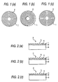
- 1 designates a solid lubrication coating film (a sliding contact layer), 2 a peripheral groove, 3 a ridge portion, 4 a root portion, 6 an intermediate layer, 8 a base member, and 10 a slide member, respectively.
- the grooves to be formed in the sliding surface of the slide member are not limited to any specific arrangements, provided that they can secure the above-mentioned structure. That is, the plurality of grooves, which are concentric with one another and extend in the peripheral direction of the sliding surface, (which are hereinafter referred to as peripheral grooves), as shown in Fig. 1 which is a plan view of the slide member, may be concentric-circle-shaped grooves (1a) or spiral-shaped grooves (1b). Also, the grooves may not always be continuous with one another; that is, they may be continuous (1a or 1b) or they may be discontinuous (for example, 1c).
- peripheral direction it may not be always the peripheral direction of a circular shape but it may be the peripheral direction of an elliptical shape; that is, the peripheral direction can be set properly according to the shape of a base member to be used.
- the direction of the peripheral grooves preferably, may be substantially the sliding direction of the slide member.
- the section shapes of the peripheral grooves may be such that the mutually adjoining ones of the grooves respectively form the ridge portions between them; and, the shapes of the root portions of the grooves are not limited to specific ones, provided that they are able to secure the lubricating oil.
- the semicircular shape and triangular shape are preferred, because, in the case of these shapes, the rate of formation of the ridge portions is high and thus the contact surface pressure in the early stage is high, so that the root portions can be easily worn and deformed to thereby be able to attain a good proper initial running-in. property.
- the semicircular shape is preferred because it is able to secure the lubricating oil in a large quantity.
- each of the peripheral grooves are not limited to specific ones but they can be properly set according to the shape and size of a base member and according to the required sliding property of the slide member.
- the depth of each of the peripheral grooves normally, may be in the range of 1 to 20 ⁇ m and, preferably, in the range of 1 to 7 ⁇ m.
- the pitch of each peripheral groove normally, may be in the range of 0.05 to 1 mm and, preferably, in the range of 0.1 to 0.5 m.
- the depths and/or pitches of the peripheral grooves may not all be uniform but, according to the peripheral speed differences or according to differences in the sliding properties, the depths and/or pitches may be varied properly on the sliding surface.
- Amethod for forming the peripheral grooves of the invention on the sliding surface is not limited to a specific one.
- a method in which a slide member with a solid lubrication coating film as a sliding contact layer is cut worked at a given speed on a lathe using a chip having a given shape or a method for transferring a groove shape using a press or a roller.
- peripheral grooves may be formed on a base member or an intermediate layer disposed on a base member, a solid lubrication coating filmmay be applied on the peripheral grooves, with the result that the peripheral grooves can be formed on the sliding surface of the slide member.
- the flat-plate-shaped base member used in the slide member is not limited to a specific member but there can be used various base members which are conventionally known in the field of slide members. Specifically, there can be used an iron-system or aluminum-system member, a composite member made of aluminum members fixed and connected together, a metal member made of iron-system metal such as steel or stainless steel, a metal member made of copper-system metal such as a copper alloy, a metal member made of aluminum-system metal such as an aluminum alloy, or a member made of resin.
- As the aluminum-systemmaterial preferably, there may be used A390 in which pro-eutectic Si is precipitated.
- the surface thereof may be roughened.
- the roughness of the surface preferably, may be set in the range of 0.4 to 25 ⁇ mRz and, more preferably, in the range of 0.6 to 20 ⁇ mRz. That is, in case where the surface roughness is set within this range, the above object can be attained effectively.
- the method for forming the roughened surface in the base member there can be employed a shot blasting method or an etching method.
- the solid lubrication coating film of the invention is a film which contains solid lubricant and normally contains thermosetting resin as a binder.
- the solid lubricant which can be used in the invention, is not limited to any specific one but there are available molybdenum disulfide (MoS 2 ), graphite, h-BN, tungsten disulfide (WS 2 ), poly-4-ethylene fluoride (which is hereinafter referred to as PTFE), fluorine-system resin, Pb, and Cf.
- MoS 2 molybdenum disulfide
- WS 2 tungsten disulfide
- PTFE poly-4-ethylene fluoride
- fluorine-system resin Pb
- Cf fluorine-system resin
- the present solid lubricant can reduce and stabilize the coefficient of friction as well as can prevent occurrence of seizure.
- the average diameter of the grains of the solid lubricant preferably, may be 15 ⁇ m or less and, more preferably, may be
- a solid lubrication coating film (which is also hereinafter referred to as a film simply) according to the invention, most preferably, may contain at least one of PTFE and graphite. In this case, there can be obtained not only more stable low friction property but also excellent wear resistance.
- PTFE especially, it is preferred to use granulated burned poly-4-ethylene fluoride.
- the above-mentioned burned PTFE means one that can be produced when PTFE powder obtained by suspension polymerization or by emulsion polymerization is raised in temperature (is burned) up to its melting point and is then granulated.
- the burned PTFE also includes one which, before burned, is compression molded and, after burned, is granulated.
- the powder obtained by suspension polymerization is used as molding powder, while the powder obtained by emulsion polymerization is used as fine powder. Due to use of such burned powder, as PTFE, there can be obtained relatively hard one, which can provide not only an excellent low friction property but also excellent wear resistance.
- the above-mentioned burned PTFE is granular.
- the average grain diameter thereof is not limitative, use of PTFE having an average grain diameter of 7 ⁇ m or more can provide more excellent low friction property and more excellent wear resistance.
- PTFE having an average grain diameter of less than 7 ⁇ m is used, PTFE is dispersed finely in the binder and thus the friction property of the binder can be preferably enhanced.
- 0.5 to 10 mass % of PTFE having an average grain diameter of 7 ⁇ m or more and 2 to 30 mass % of PTFE having an average grain diameter of less than 7 ⁇ m may be combined together.
- Graphite may preferably have a high degree of crystallization. More preferably, graphite may have an inter-surface clearance of 3.5 or less and, in this case, graphite can provide an effect that it can stabilize the friction torque thereof during the sliding motion of the slide member.
- the term "to stabilize the friction torque” means to reduce variations in the friction coefficient.
- Graphite may be natural graphite or artificial graphite. However, preferably, artificial graphite may be used from the viewpoint of wear resistance.
- the average grain diameter of graphite is not limitative, use of graphite having an average grain diameter of 10 ⁇ m or more can further enhance the wear resistance thereof when it receives a load.
- graphite having an average grain diameter of less than 10 ⁇ m graphite is finely dispersed in the binder, which preferably can enhance the wear property of the binder and also can stabilize the friction toque. Therefore, preferably, 0.5 to 5 mass % of graphite having an average grain diameter of 10 ⁇ m or more and 13 to 35 mass % of graphite having an average grain diameter of less than 10 ⁇ m may be combined together.
- the content of PTFE contained in the film material preferably, may be 10 to 40 mass % and, more preferably, 22 to 35 mass %; and, the graphite content of the film material, preferably, may be 3 to 40 mass % and, more preferably, 5 to 30 mass %.
- the total content of PTFE and graphite preferably, maybe 70 mass % or less in the coating filmmaterial. In case where the PTFE content is less than 10 mass %, lubrication on the sliding surface is insufficient and thus the friction coefficient increases; and, on the other hand, in case where the PTFE content is more than 40 mass %, the material strength is lowered and thus the wear resistance is reduced.
- the load capacity is lowered and thus the wear resistance is reduced; and, on the other hand, in case where the graphite content is more than 40 mass %, lubrication on the sliding surface is insufficient and thus the friction coefficient increases.
- PTFE having an average grain diameter of 7 ⁇ m or more may be contained by 0.5 to 10 mass %, more preferably, by 2 to 7 mass % and PTFE having an average grain diameter of less than 7 ⁇ m may be contained by 2 to 30 mass %, more preferably, by 5 to 25 mass %.
- the film coated surface is roughened and thus the friction coefficient increases; and, on the other hand, in case where the content of PTFE having an average grain diameter of less than 7 ⁇ m is more than 30 mass %, unfavorably, the material strength is weakened and thus the wear resistance is lowered.
- graphite having an average grain diameter of 10 ⁇ m or more may be contained by 0.5 to 5 mass %, more preferably, by 1 to 3 mass % and graphite having an average grain diameter of less than 10 ⁇ m may be contained by 13 to 35 mass %, more preferably, by 20 to 30 mass %.
- the resin binder that can be used in the film of the slide member according to the invention, for example, there are available polyimide resin (PI) , polyamide-imide-systemresin (PAI), epoxy resin, phenol resin, polyamide (nylon), fluoro-resin (PTFE, FEP), and elastomer.
- PI polyimide resin
- PAI polyamide-imide-systemresin
- epoxy resin epoxy resin
- phenol resin polyamide
- polyamide polyamide (nylon)
- fluoro-resin PTFE, FEP
- elastomer elastomer
- the above-mentioned resin binder can be selectively used according to using conditions.
- the above-mentioned film may preferably contain the resin binder by 30 to 80 mass %. Use of this content can maintain the holdability of the solid lubricant and abrasives in the coating film containing thermosetting resin, can obtain sufficient seizure resistance and running-in property, and allows the acute-angle-shaped hard powder to fulfill its grinding function effectively.
- PI and/or PAI may be contained by 30 to 77 mass %.
- Use of this content can maintain the holdability of the solid lubricant and abrasives in the coating film containing thermosetting resin, can obtain sufficient seizure resistance and running-in property, and allows the above-mentioned PTFE and graphite to fulfill the above-mentioned functions thereof effectively.
- a film material according to the invention in addition to the above-mentioned materials, can further contain an extreme pressure agent.
- an extreme pressure agent there are available sulfur containing metal compounds such as Zns, Ag 2 S, CuS, FeS, FeS 2 , Sb 3 S 2 , PbS, Bi 2 S 3 , CdS; sulfur containing compounds such as thiram, morpholine disulfide, dithionate, sulfide, sulfoxide, sulfonic acid, thiophosphonate, thiocarbonate, dithiocarbonate, alkylthiocarbamoyl, olefin sulfide; halogen-system compounds such as chlorinated hydrocarbon; organic-metal-system compounds such as thiophosphate (dithiophosphate), and thiocalbamate; and, organic molybdenum compounds such as molybdenum dithiophosphate and molybdenum dithiocarbamate.
- organic solvent can adjust the viscosity of the film composition to thereby facilitate the mixture thereof; and, it can be used with no special limit, provided that it is able to solve polyamideimide resin.
- resin is polyamideimide
- xylene, N-methyl-2-pyrrolidone, and toluene there can be used xylene, N-methyl-2-pyrrolidone, and toluene.
- an intermediate layer is interposed between the base member and sliding contact layer and can be used to keep the sliding performance of the slide member in a good level even in case where the sliding contact layer is worn.
- electrolytic or no-electrolytic Sn plating As the material that can provide a good sliding property, there are available electrolytic or no-electrolytic Sn plating, electrolytic Sn alloy plating, electrolytic or no-electrolytic Cu plating, electrolytic copper alloy (a copper alloy to which there is added an element such as Pb, Sn, In, or Ag capable of improving the sliding performance) plating, thermally-sprayed copper alloy, clad copper (alloy), and sintered copper (alloy); that is, preferably, the intermediate layers may be composed of the above materials.
- thermosetting resin attached on these intermediate layers flows together with the solid lubricant and is transferred from the low-load area of the swash plate to the high-load area thereof by a shoe
- the resin and other materials are pressure attached to their transferred area where the film has been worn in part or completely.
- a base member made of iron-system material is used as the base member of the intermediate layers
- Ni-plated layer which can improve the close adhesion property of the intermediate layers.
- a chlomate treatment can be enforced on the intermediate layers.
- a copper-aluminum composite thermally-sprayed layer there may be used as the intermediate layer.
- a copper-aluminum composite thermally-sprayed layer disclosed in JP-A-2001-20054 in which copper or a copper alloy (which is hereinafter referred to as a copper alloy simply) contains at least an undissolved phase and aluminum or an aluminum alloy (which is hereinafter referred to as an aluminum alloy simply) contains at least a dissolved phase.
- the term "dissolved phase” means a system which is dissolved during the thermal spray treatment of the above-mentioned composite material, that is, a state in which the material is dissolved and solidified during the thermal spray treatment.
- the thermal spray treatment when copper alloy powder and aluminum alloy powder are equal in the average grain diameter, the aluminum alloy powder is dissolved; and, when the average grain diameter of the aluminum alloy powder is much larger than that of the copper alloy powder, the latter is also dissolved. That is, by making use of this tendency, there can be manufactured a copper-aluminum composite material in which at least part of the aluminumalloy powder thereof is dissolved and the remaining portions of the aluminum alloy powder substantially maintain the property of solid powder.
- the thus-manufactured copper-aluminum composite material is more excellent in the pure aluminum wear resistance than copper (alloy) and, further, many of aluminum alloys, in the cast states thereof, are excellent in the wear resistance.
- the wear resistance of the whole of the composite material can be enhanced over the copper (alloy).
- the former may be 80 to 30% by weight and the latter may be the remaining percentage (that is, 20 to 70%) by weight.
- the base member After a base member made of copper, stainless steel, copper alloy, aluminum alloy or resin is worked into a given shape, the base member is degreased in an alkaline treatment solution such as caustic soda and is then rinsed by water or by warm water to thereby remove alkali attached to the surface of the base material.
- an alkaline treatment solution such as caustic soda
- the surface of a lining may be roughened by a chemical treatment consisting of alkaline etching and acid cleaning, or the lining surface may be roughened by a mechanical treatment such as shot blasting, or the lining surface may be poled to form uneven portions on the lining surface.
- a chemical treatment may be enforced on the lining surface by using a layer of zinc phosphate or zinc calcium phosphate having a thickness of 0.1 to 5 ⁇ m.
- the base treatment such as poling and chemical treatment are combined, there can be obtained a lubrication film layer which has a very high degree of close contact property.
- thermal spray method there can be employed various thermal spray methods which are disclosed in the above-mentioned "toraibolojisuto", Page 20, Fig. 2; and, preferably, there may be used a high velocity oxyfuel spray method (HVOF).
- HVOF high velocity oxyfuel spray method
- the solid solution film composition which has been dried after degreasing and diluted using a proper diluent, is applied onto a lining by spraying and is then dried and burned at the temperature of 150 to 300° c.
- the film surface may be smoothened by buffing.
- the solid solution film can be formed according to not only a spray coating method (for example, an air spray method, and an air electrostatic coating method) but also a tumbling method, a dipping method, a brushing method, a roll-type printing method (for example, a screen printing method, a pad printing method), and a bell-type rotation-atomization-type electrostatic coating method.
- the thickness of the solid lubrication film preferably, may be in the range of 1 to 50 ⁇ m.
- the solid lubrication film is cut worked at a given feed speed on a lathe using a chip having a given shape, or a groove shape is transferred to the surface of the solid lubrication film using a press or a roller. In this manner, a slide member according to the invention can be obtained.
- a slide member according to the invention can be applied to a swash plate for a compressor, a thrust washer, and a crank washer.
- thermal spraying a thermal spray material consisting of Cu 44.0%, Sn 2.0%, Pb 9.0%, Al 25.0% and Si 20.0% onto a base member for a swash plate made of iron-system material, there is formed an intermediate layer.
- a solid solution film composition there was prepared raw material in such a manner that it consists of polyamideimide resin 50 mass %, PTFE (average grain diameter 5 ⁇ m) 24 mass %, and graphite (average grain diameter 1 ⁇ m) 20 mass %.
- N-methyl-2-pyrrolidone as the solvent of the resin, was added to the raw material and they were all mixed together, the mixture was applied by spray coating onto the base member with the intermediate layer formed thereon, thereby forming a solid lubrication coating film having a thickness of 40 ⁇ m.
- the solid lubrication coating film was burned at the temperature of 190° C for an hour and, next, the thus-burned solid lubrication coating film was groove worked at the feed speed of 0.16 mm on a lathe using'a diamond chip of 0.8 R (curvature), thereby forming such a peripheral groove as shown in Figs. 1a and 2a which has a depth of 4 ⁇ m and a pitch of 0.16 mm.
- a peeling occurrence state means the number of peeled portions occurred in one swash plate).
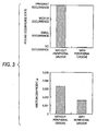
- test results show that, due to provision of a peripheral groove according to the invention, there can be obtained a slide member which is enhanced in the initial running-in property, is good in the friction characteristic and is excellent in the wear resistance.
- Patent Application 2001-076230 filed on March 16, 2001 and thus the contents thereof are cited into the present application for reference.
- a slide member with a solid lubrication coating film according to the invention is enhanced in the initial running-in property and thus can provide an excellent sliding property even under the strict sliding conditions.
- a slide member according to the invention can provide a good friction property under the fluid lubrication, boundary lubrication and dry lubrication conditions as well as is excellent in the wear resistance.
Landscapes
- Chemical & Material Sciences (AREA)
- Engineering & Computer Science (AREA)
- Organic Chemistry (AREA)
- Chemical Kinetics & Catalysis (AREA)
- Mechanical Engineering (AREA)
- General Engineering & Computer Science (AREA)
- Materials Engineering (AREA)
- Metallurgy (AREA)
- General Chemical & Material Sciences (AREA)
- Oil, Petroleum & Natural Gas (AREA)
- Life Sciences & Earth Sciences (AREA)
- Wood Science & Technology (AREA)
- Inorganic Chemistry (AREA)
- Manufacturing & Machinery (AREA)
- Health & Medical Sciences (AREA)
- Medicinal Chemistry (AREA)
- Polymers & Plastics (AREA)
- Electrochemistry (AREA)
- Lubricants (AREA)
- Sliding-Contact Bearings (AREA)
- Compressors, Vaccum Pumps And Other Relevant Systems (AREA)
Abstract
Description
Test type: 3 shoes/flat plate
Number of rotations: 2000 rpm (6.3 m/s)
Load: 3000 N (10 MPa)
Lubrication: Mist lubrication
Kind of oil: Refrigerating machine oil
Amount of oil': 1.8g/min
Time: 1 hour.
Claims (5)
- A slide member including a solid lubrication coating film on a flat-plate-shaped base member,
wherein, in the surface of said slide member, there are formed a plurality of concentrical grooves extending in the peripheral direction of said slide member surface, and, between the mutually adjoining ones of said grooves, there are formed ridge portions respectively. - The slide member as set forth in Claim 1, further including an intermediate layer formed between said base member and said solid lubrication coating film.
- The slide member as set forth in Claim 1 or 2, wherein said solid lubrication coating film includes at least one of poly-4-ethylene fluoride and graphite.
- The slide member as set forth in any one of Claims 1 to 3, wherein the depth of each of said grooves is set in the range of 1 to 20 µ m and the pitch of said groove is set in the range of 0.05 to 1 mm.
- The slide member as set forth in any one of Claims 1 to 4, wherein said slide member is a swash plate for a compressor.
Applications Claiming Priority (3)
| Application Number | Priority Date | Filing Date | Title |
|---|---|---|---|
| JP2001076230 | 2001-03-16 | ||
| JP2001076230 | 2001-03-16 | ||
| PCT/JP2002/002361 WO2002075172A1 (en) | 2001-03-16 | 2002-03-13 | Sliding material |
Publications (3)
| Publication Number | Publication Date |
|---|---|
| EP1281881A1 true EP1281881A1 (en) | 2003-02-05 |
| EP1281881A4 EP1281881A4 (en) | 2011-03-02 |
| EP1281881B1 EP1281881B1 (en) | 2019-10-30 |
Family
ID=18933202
Family Applications (1)
| Application Number | Title | Priority Date | Filing Date |
|---|---|---|---|
| EP02705132.5A Expired - Lifetime EP1281881B1 (en) | 2001-03-16 | 2002-03-13 | Sliding material |
Country Status (8)
| Country | Link |
|---|---|
| US (1) | US6921205B2 (en) |
| EP (1) | EP1281881B1 (en) |
| JP (1) | JP4376519B2 (en) |
| KR (1) | KR20030001500A (en) |
| CN (1) | CN1215267C (en) |
| BR (1) | BR0204484B1 (en) |
| HU (1) | HU228100B1 (en) |
| WO (1) | WO2002075172A1 (en) |
Cited By (16)
| Publication number | Priority date | Publication date | Assignee | Title |
|---|---|---|---|---|
| EP1584828A4 (en) * | 2003-01-08 | 2007-01-17 | Taiho Kogyo Co Ltd | SLIDING BEARING |
| EP1985856A1 (en) * | 2007-04-25 | 2008-10-29 | Kabushiki Kaisha Toyota Jidoshokki | Compressor swash plate and method of manufacturing the same |
| EP2209184A1 (en) * | 2009-01-14 | 2010-07-21 | Grundfos Management A/S | Magnetic rotor |
| EP1950279A4 (en) * | 2005-11-15 | 2012-09-19 | Idemitsu Kosan Co | OIL FOR REFRIGERATING MACHINE |
| ITBG20120023A1 (en) * | 2012-05-08 | 2013-11-09 | Technymon Srl | COMPOSITION AND METHOD FOR OBTAINING A MULTILAYER STRIPED BEARING |
| CN103671024A (en) * | 2012-09-17 | 2014-03-26 | 苏州中成汽车空调压缩机有限公司 | Main shaft swash plate mechanism for compressor |
| WO2016029235A1 (en) * | 2014-08-27 | 2016-03-03 | Miba Gleitlager Gmbh | Sliding bearing element |
| EP2878820A4 (en) * | 2012-06-07 | 2016-05-11 | Ntn Toyo Bearing Co Ltd | Swash plate for swash plate compressor, method for manufacturing same, and swash plate compressor |
| EP2636914A4 (en) * | 2010-11-02 | 2016-05-25 | Taiho Kogyo Co Ltd | BEARINGS |
| EP2623780A4 (en) * | 2010-09-28 | 2016-10-19 | Ntn Toyo Bearing Co Ltd | Swash plate of swash plate compressor and swash plate compressor |
| EP2224146A4 (en) * | 2007-12-21 | 2016-12-28 | Taiho Kogyo Co Ltd | SLIDING ELEMENT FOR THRUST BEARING |
| EP3051135A4 (en) * | 2013-09-27 | 2017-08-02 | Taiho Kogyo Co., Ltd | Scroll member and scroll-type fluid machine |
| EP2631482A4 (en) * | 2010-11-24 | 2018-01-24 | Taiho Kogyo Co., Ltd | Swash plate compressor |
| US10443654B2 (en) | 2014-03-06 | 2019-10-15 | Taiho Kogyo Co., Ltd. | Bearing and scroll-type fluid machine |
| EP3543322A4 (en) * | 2016-11-17 | 2020-07-15 | Taiho Kogyo Co., Ltd. | RESIN COMPOSITION AND SLIDING ELEMENT |
| US11352581B2 (en) | 2016-11-17 | 2022-06-07 | Taiho Kogyo Co., Ltd. | Resin composition and sliding member |
Families Citing this family (45)
| Publication number | Priority date | Publication date | Assignee | Title |
|---|---|---|---|---|
| JP2006008994A (en) * | 2004-05-21 | 2006-01-12 | Toyota Central Res & Dev Lab Inc | Sliding coating, sliding member, sliding coating composition, sliding device, swash plate compressor, sliding coating forming method, and sliding member manufacturing method |
| JP4848121B2 (en) * | 2004-06-10 | 2011-12-28 | Ntn株式会社 | Sliding material |
| JP2006002716A (en) * | 2004-06-21 | 2006-01-05 | Zexel Valeo Climate Control Corp | Sealing structure for compressor |
| JP2006070838A (en) * | 2004-09-03 | 2006-03-16 | Taiho Kogyo Co Ltd | Sliding member |
| DE102004044519A1 (en) * | 2004-09-15 | 2006-03-30 | Wieland-Werke Ag | Sliding body and method for producing a slider and its use |
| EP1818553B1 (en) | 2004-12-01 | 2010-03-03 | JTEKT Corporation | Touchdown bearing |
| JP4539861B2 (en) * | 2004-12-01 | 2010-09-08 | 株式会社ジェイテクト | Touchdown bearing |
| JP4927349B2 (en) * | 2005-05-11 | 2012-05-09 | 出光興産株式会社 | Refrigerator oil composition, compressor and refrigeration apparatus using the same |
| DE102006013399A1 (en) | 2005-12-21 | 2007-07-05 | Mahle International Gmbh | Connecting rod for internal combustion engine, has small connecting rod eye for holding piston pin and large connecting rod eye for holding crank pin whereby bore is provided with coating having resin with solid lubricant particles |
| JP4569829B2 (en) * | 2006-01-23 | 2010-10-27 | 株式会社豊田自動織機 | Sliding member |
| CN101970624A (en) * | 2007-11-22 | 2011-02-09 | 出光兴产株式会社 | Lubricating oil composition for refrigerator and compressor using same |
| JP5321943B2 (en) * | 2008-03-03 | 2013-10-23 | Ntn株式会社 | Swash plate compressor and swash plate compressor |
| JP2009270609A (en) * | 2008-05-05 | 2009-11-19 | Sanden Corp | Sliding member |
| JP5298838B2 (en) * | 2008-12-25 | 2013-09-25 | 大豊工業株式会社 | Swash plate and its manufacturing method |
| JP5229576B2 (en) | 2009-01-30 | 2013-07-03 | 大豊工業株式会社 | Swash plate compressor |
| DE102009002425A1 (en) * | 2009-04-16 | 2010-10-21 | Albert Handtmann Elteka Gmbh & Co Kg | Bearing arrangement with bearing element made of Eltimid |
| JP5594466B2 (en) | 2010-07-28 | 2014-09-24 | 大豊工業株式会社 | Swash plate compressor |
| JP5695362B2 (en) * | 2010-08-05 | 2015-04-01 | 株式会社サンコー | Gas stopper |
| FR2967199B1 (en) * | 2010-11-10 | 2013-11-01 | Vallourec Mannesmann Oil & Gas France | METHOD FOR COATING A THREADED TUBULAR COMPONENT, THREADED TUBULAR COMPONENT AND RESULTING SEAL |
| BR112013013301A2 (en) * | 2010-12-02 | 2016-09-06 | Taiho Kogyo Co Ltd | oscillating plate compressor type oscillating plate |
| CN103261696B (en) * | 2010-12-22 | 2016-08-10 | 大金工业株式会社 | Compressor |
| JP5041059B2 (en) * | 2010-12-27 | 2012-10-03 | ダイキン工業株式会社 | Compressor |
| EP2660472B1 (en) | 2010-12-27 | 2015-08-26 | Daikin Industries, Ltd. | Compressor |
| JP4934749B1 (en) * | 2011-02-23 | 2012-05-16 | 株式会社小松製作所 | Variable displacement hydraulic pump / motor |
| JP5767959B2 (en) | 2011-12-22 | 2015-08-26 | 大豊工業株式会社 | Sliding member |
| JP5621990B2 (en) | 2011-12-22 | 2014-11-12 | 大豊工業株式会社 | Sliding member |
| JP5731991B2 (en) | 2012-01-20 | 2015-06-10 | 大豊工業株式会社 | Sliding member |
| CN102635533A (en) * | 2012-03-19 | 2012-08-15 | 桐乡市易锋机械厂 | Swash plate outer ring of compressor of automobile air conditioner and method for machining swash plate outer ring |
| JP5850777B2 (en) * | 2012-03-23 | 2016-02-03 | 大同メタル工業株式会社 | Sliding member |
| CN103671023A (en) * | 2012-09-17 | 2014-03-26 | 苏州中成汽车空调压缩机有限公司 | Tilting frame assembly |
| GB2508915A (en) * | 2012-12-14 | 2014-06-18 | Mahle Int Gmbh | A thrust washer for a sliding bearing |
| EP2940327B1 (en) * | 2012-12-27 | 2020-06-24 | Taiho Kogyo Co., Ltd | Sliding member |
| JP6210814B2 (en) * | 2013-09-26 | 2017-10-11 | ポリプラスチックス株式会社 | Sliding member |
| JP2015042907A (en) * | 2014-12-05 | 2015-03-05 | 株式会社サンコー | Gas cock |
| JP6568395B2 (en) | 2015-04-27 | 2019-08-28 | 大同メタル工業株式会社 | Thrust washer, resin coating layer used therefor, paint for forming resin coating layer, and internal combustion engine provided with thrust washer |
| WO2016174909A1 (en) * | 2015-04-27 | 2016-11-03 | 大同メタル工業株式会社 | Sliding member and thrust washer |
| KR20170018718A (en) | 2015-08-10 | 2017-02-20 | 삼성전자주식회사 | Transparent electrode using amorphous alloy and method for manufacturing the same |
| JP6177852B2 (en) | 2015-10-01 | 2017-08-09 | 大豊工業株式会社 | Swash plate for compressor and compressor having the same |
| JP6706185B2 (en) * | 2016-09-30 | 2020-06-03 | 大豊工業株式会社 | Swash plate for compressor |
| CN106640976B (en) * | 2016-12-20 | 2019-02-26 | 湖南崇德工业科技有限公司 | A kind of thrust bearing |
| JP2019082148A (en) | 2017-10-31 | 2019-05-30 | 大豊工業株式会社 | Swash plate |
| FR3073586B1 (en) * | 2017-11-15 | 2020-01-03 | Arianegroup Sas | SELF-LUBRICATING RING FOR FLUID BEARING AND METHOD FOR MANUFACTURING SUCH A RING |
| JP7075251B2 (en) | 2018-03-22 | 2022-05-25 | 大同メタル工業株式会社 | Sliding member |
| CN110242575B (en) * | 2019-06-17 | 2021-01-05 | 珠海格力节能环保制冷技术研究中心有限公司 | Friction piece, compressor, air conditioner and friction surface treatment method |
| JP6768991B1 (en) * | 2020-01-07 | 2020-10-14 | 三菱電機株式会社 | Scroll parts, scroll compressors equipped with these scroll parts, and methods for manufacturing scroll parts |
Family Cites Families (16)
| Publication number | Priority date | Publication date | Assignee | Title |
|---|---|---|---|---|
| FR2234815A5 (en) * | 1973-06-21 | 1975-01-17 | Commissariat Energie Atomique | Dry rotary sealing and lubrification system - uses solid lubricant injected into porous body formed of metal powder |
| JPS5986714A (en) * | 1982-11-08 | 1984-05-19 | Taiho Kogyo Co Ltd | Sliding member |
| JPS6026188A (en) * | 1983-07-20 | 1985-02-09 | Taiho Kogyo Co Ltd | Swash plate type compressor |
| JPS60217329A (en) * | 1984-04-13 | 1985-10-30 | Matsushita Electric Ind Co Ltd | Rotating polygon mirror assembly |
| AT385822B (en) * | 1984-02-27 | 1988-05-25 | Miba Gleitlager Ag | COMPOSITE SLIDING BEARING |
| US4683804A (en) * | 1985-01-18 | 1987-08-04 | Taiho Kogyo Kabushiki Kaisha | Swash plate type compressor shoe |
| JPH0697033B2 (en) * | 1988-11-11 | 1994-11-30 | 株式会社豊田自動織機製作所 | Swash plate type compressor |
| JPH074435A (en) * | 1993-06-16 | 1995-01-10 | Nagata Buhin Seizo Kk | Bearing member and wear preventing method for bearing member |
| JPH07233816A (en) | 1994-02-22 | 1995-09-05 | Toshiba Corp | Bearing device |
| JP2974044B2 (en) * | 1994-03-18 | 1999-11-08 | 大豊工業株式会社 | Plain bearing |
| JP2850941B2 (en) | 1994-03-18 | 1999-01-27 | 大豊工業株式会社 | Plain bearing |
| JP3642077B2 (en) * | 1995-01-27 | 2005-04-27 | 大豊工業株式会社 | Swash plate compressor swash plate |
| DE19504607A1 (en) | 1995-02-11 | 1996-08-14 | Schlafhorst & Co W | Sliver feed device for OE spinning machines |
| JP3568061B2 (en) * | 1995-05-17 | 2004-09-22 | 大豊工業株式会社 | Swash plate of swash plate compressor and combination of swash plate and shoe |
| JP4023872B2 (en) * | 1997-06-26 | 2007-12-19 | 大豊工業株式会社 | Swash plate compressor swash plate |
| JPH11193780A (en) | 1997-12-26 | 1999-07-21 | Toyota Autom Loom Works Ltd | Single-headed piston swash plate type compression machine and method for manufacturing swash plate |
-
2002
- 2002-03-13 CN CNB02800714XA patent/CN1215267C/en not_active Expired - Lifetime
- 2002-03-13 EP EP02705132.5A patent/EP1281881B1/en not_active Expired - Lifetime
- 2002-03-13 KR KR1020027015371A patent/KR20030001500A/en not_active Ceased
- 2002-03-13 JP JP2002573547A patent/JP4376519B2/en not_active Expired - Lifetime
- 2002-03-13 HU HU0302324A patent/HU228100B1/en not_active IP Right Cessation
- 2002-03-13 BR BRPI0204484-6A patent/BR0204484B1/en not_active IP Right Cessation
- 2002-03-13 US US10/276,241 patent/US6921205B2/en not_active Expired - Lifetime
- 2002-03-13 WO PCT/JP2002/002361 patent/WO2002075172A1/en not_active Ceased
Cited By (19)
| Publication number | Priority date | Publication date | Assignee | Title |
|---|---|---|---|---|
| EP1584828A4 (en) * | 2003-01-08 | 2007-01-17 | Taiho Kogyo Co Ltd | SLIDING BEARING |
| EP1950279A4 (en) * | 2005-11-15 | 2012-09-19 | Idemitsu Kosan Co | OIL FOR REFRIGERATING MACHINE |
| EP1985856A1 (en) * | 2007-04-25 | 2008-10-29 | Kabushiki Kaisha Toyota Jidoshokki | Compressor swash plate and method of manufacturing the same |
| EP2224146A4 (en) * | 2007-12-21 | 2016-12-28 | Taiho Kogyo Co Ltd | SLIDING ELEMENT FOR THRUST BEARING |
| WO2010081653A1 (en) * | 2009-01-14 | 2010-07-22 | Grundfos Management A/S | Rotor made of magnetic material |
| EP2209184A1 (en) * | 2009-01-14 | 2010-07-21 | Grundfos Management A/S | Magnetic rotor |
| US8729768B2 (en) | 2009-01-14 | 2014-05-20 | Grundfos Management A/S | Rotor made of magnetic material |
| EP2623780A4 (en) * | 2010-09-28 | 2016-10-19 | Ntn Toyo Bearing Co Ltd | Swash plate of swash plate compressor and swash plate compressor |
| EP2636914A4 (en) * | 2010-11-02 | 2016-05-25 | Taiho Kogyo Co Ltd | BEARINGS |
| EP2631482A4 (en) * | 2010-11-24 | 2018-01-24 | Taiho Kogyo Co., Ltd | Swash plate compressor |
| ITBG20120023A1 (en) * | 2012-05-08 | 2013-11-09 | Technymon Srl | COMPOSITION AND METHOD FOR OBTAINING A MULTILAYER STRIPED BEARING |
| EP2878820A4 (en) * | 2012-06-07 | 2016-05-11 | Ntn Toyo Bearing Co Ltd | Swash plate for swash plate compressor, method for manufacturing same, and swash plate compressor |
| CN103671024A (en) * | 2012-09-17 | 2014-03-26 | 苏州中成汽车空调压缩机有限公司 | Main shaft swash plate mechanism for compressor |
| EP3051135A4 (en) * | 2013-09-27 | 2017-08-02 | Taiho Kogyo Co., Ltd | Scroll member and scroll-type fluid machine |
| US10443654B2 (en) | 2014-03-06 | 2019-10-15 | Taiho Kogyo Co., Ltd. | Bearing and scroll-type fluid machine |
| WO2016029235A1 (en) * | 2014-08-27 | 2016-03-03 | Miba Gleitlager Gmbh | Sliding bearing element |
| EP3543322A4 (en) * | 2016-11-17 | 2020-07-15 | Taiho Kogyo Co., Ltd. | RESIN COMPOSITION AND SLIDING ELEMENT |
| US11352581B2 (en) | 2016-11-17 | 2022-06-07 | Taiho Kogyo Co., Ltd. | Resin composition and sliding member |
| US11421173B2 (en) | 2016-11-17 | 2022-08-23 | Taiho Kogyo Co., Ltd. | Resin composition and sliding member |
Also Published As
| Publication number | Publication date |
|---|---|
| JP4376519B2 (en) | 2009-12-02 |
| EP1281881A4 (en) | 2011-03-02 |
| HUP0302324A3 (en) | 2005-05-30 |
| BR0204484B1 (en) | 2010-08-10 |
| HUP0302324A2 (en) | 2003-10-28 |
| EP1281881B1 (en) | 2019-10-30 |
| US20030111511A1 (en) | 2003-06-19 |
| US6921205B2 (en) | 2005-07-26 |
| JPWO2002075172A1 (en) | 2004-07-08 |
| BR0204484A (en) | 2003-03-11 |
| HU228100B1 (en) | 2012-10-29 |
| WO2002075172A1 (en) | 2002-09-26 |
| KR20030001500A (en) | 2003-01-06 |
| CN1215267C (en) | 2005-08-17 |
| CN1459006A (en) | 2003-11-26 |
Similar Documents
| Publication | Publication Date | Title |
|---|---|---|
| US6921205B2 (en) | Sliding material | |
| KR100454306B1 (en) | Plain bearing | |
| US8939644B2 (en) | Swash plate and production method of the same | |
| KR100493218B1 (en) | Sliding member and sliding device | |
| US5525246A (en) | Sliding-Bearing Material | |
| JPH11106779A (en) | Solid lubricating coating composition and sliding bearing material using the same | |
| JP4485131B2 (en) | Plain bearing | |
| KR100594335B1 (en) | Compressor | |
| CN101400453A (en) | Component, especially a preform, comprising a coating | |
| JP3764754B2 (en) | Swash plate compressor | |
| JPH11325077A (en) | Multiple-layered slide material | |
| JP2002005063A (en) | Rotary compressor | |
| JP2006008994A (en) | Sliding coating, sliding member, sliding coating composition, sliding device, swash plate compressor, sliding coating forming method, and sliding member manufacturing method | |
| JPH1162970A (en) | Floating bush for turbocharger | |
| KR20070032248A (en) | Bearing member | |
| JP2002088484A (en) | Sliding material | |
| JP4784829B2 (en) | Sliding member manufacturing method and sliding member | |
| JP2007205334A (en) | Swash plate of swash plate compressor and swash plate compressor |
Legal Events
| Date | Code | Title | Description |
|---|---|---|---|
| PUAI | Public reference made under article 153(3) epc to a published international application that has entered the european phase |
Free format text: ORIGINAL CODE: 0009012 |
|
| 17P | Request for examination filed |
Effective date: 20021115 |
|
| AK | Designated contracting states |
Designated state(s): AT BE CH CY DE DK ES FI FR GB GR IE IT LI LU MC NL PT SE TR |
|
| A4 | Supplementary search report drawn up and despatched |
Effective date: 20110201 |
|
| RIC1 | Information provided on ipc code assigned before grant |
Ipc: F16C 33/12 20060101ALI20110126BHEP Ipc: F04B 27/08 20060101AFI20110126BHEP Ipc: F04B 39/00 20060101ALI20110126BHEP Ipc: F16C 33/10 20060101ALI20110126BHEP |
|
| 17Q | First examination report despatched |
Effective date: 20110617 |
|
| STAA | Information on the status of an ep patent application or granted ep patent |
Free format text: STATUS: EXAMINATION IS IN PROGRESS |
|
| GRAP | Despatch of communication of intention to grant a patent |
Free format text: ORIGINAL CODE: EPIDOSNIGR1 |
|
| STAA | Information on the status of an ep patent application or granted ep patent |
Free format text: STATUS: GRANT OF PATENT IS INTENDED |
|
| INTG | Intention to grant announced |
Effective date: 20181122 |
|
| RIC1 | Information provided on ipc code assigned before grant |
Ipc: F04B 39/00 20060101ALI20110126BHEP Ipc: F04B 27/08 20060101AFI20110126BHEP Ipc: F16C 33/10 20060101ALI20110126BHEP Ipc: F16C 33/12 20060101ALI20110126BHEP |
|
| GRAJ | Information related to disapproval of communication of intention to grant by the applicant or resumption of examination proceedings by the epo deleted |
Free format text: ORIGINAL CODE: EPIDOSDIGR1 |
|
| STAA | Information on the status of an ep patent application or granted ep patent |
Free format text: STATUS: EXAMINATION IS IN PROGRESS |
|
| GRAP | Despatch of communication of intention to grant a patent |
Free format text: ORIGINAL CODE: EPIDOSNIGR1 |
|
| STAA | Information on the status of an ep patent application or granted ep patent |
Free format text: STATUS: GRANT OF PATENT IS INTENDED |
|
| INTC | Intention to grant announced (deleted) | ||
| RIC1 | Information provided on ipc code assigned before grant |
Ipc: C23C 18/52 20060101ALI20190401BHEP Ipc: C10M 107/38 20060101ALI20190401BHEP Ipc: F16C 33/20 20060101ALI20190401BHEP Ipc: F16C 17/04 20060101ALI20190401BHEP Ipc: F04B 27/08 20060101AFI20190401BHEP Ipc: C09D 177/00 20060101ALI20190401BHEP Ipc: C23C 22/22 20060101ALI20190401BHEP Ipc: C10M 103/06 20060101ALI20190401BHEP Ipc: C10M 103/02 20060101ALI20190401BHEP Ipc: C08G 73/14 20060101ALI20190401BHEP Ipc: F16C 33/12 20060101ALI20190401BHEP Ipc: F16C 33/14 20060101ALI20190401BHEP Ipc: C09D 179/08 20060101ALI20190401BHEP Ipc: C23C 28/00 20060101ALI20190401BHEP Ipc: C09D 161/08 20060101ALI20190401BHEP Ipc: C23C 18/38 20060101ALI20190401BHEP Ipc: C09D 161/06 20060101ALI20190401BHEP Ipc: C25D 7/10 20060101ALI20190401BHEP Ipc: F04B 39/00 20060101ALI20190401BHEP Ipc: F04B 27/10 20060101ALI20190401BHEP Ipc: F16C 33/10 20060101ALI20190401BHEP |
|
| INTG | Intention to grant announced |
Effective date: 20190416 |
|
| GRAJ | Information related to disapproval of communication of intention to grant by the applicant or resumption of examination proceedings by the epo deleted |
Free format text: ORIGINAL CODE: EPIDOSDIGR1 |
|
| STAA | Information on the status of an ep patent application or granted ep patent |
Free format text: STATUS: EXAMINATION IS IN PROGRESS |
|
| GRAP | Despatch of communication of intention to grant a patent |
Free format text: ORIGINAL CODE: EPIDOSNIGR1 |
|
| STAA | Information on the status of an ep patent application or granted ep patent |
Free format text: STATUS: GRANT OF PATENT IS INTENDED |
|
| INTC | Intention to grant announced (deleted) | ||
| INTG | Intention to grant announced |
Effective date: 20190624 |
|
| GRAS | Grant fee paid |
Free format text: ORIGINAL CODE: EPIDOSNIGR3 |
|
| GRAA | (expected) grant |
Free format text: ORIGINAL CODE: 0009210 |
|
| STAA | Information on the status of an ep patent application or granted ep patent |
Free format text: STATUS: THE PATENT HAS BEEN GRANTED |
|
| AK | Designated contracting states |
Kind code of ref document: B1 Designated state(s): AT BE CH CY DE DK ES FI FR GB GR IE IT LI LU MC NL PT SE TR |
|
| REG | Reference to a national code |
Ref country code: GB Ref legal event code: FG4D |
|
| REG | Reference to a national code |
Ref country code: CH Ref legal event code: EP |
|
| REG | Reference to a national code |
Ref country code: AT Ref legal event code: REF Ref document number: 1196423 Country of ref document: AT Kind code of ref document: T Effective date: 20191115 |
|
| REG | Reference to a national code |
Ref country code: DE Ref legal event code: R096 Ref document number: 60250027 Country of ref document: DE |
|
| REG | Reference to a national code |
Ref country code: IE Ref legal event code: FG4D |
|
| PG25 | Lapsed in a contracting state [announced via postgrant information from national office to epo] |
Ref country code: PT Free format text: LAPSE BECAUSE OF FAILURE TO SUBMIT A TRANSLATION OF THE DESCRIPTION OR TO PAY THE FEE WITHIN THE PRESCRIBED TIME-LIMIT Effective date: 20200302 Ref country code: SE Free format text: LAPSE BECAUSE OF FAILURE TO SUBMIT A TRANSLATION OF THE DESCRIPTION OR TO PAY THE FEE WITHIN THE PRESCRIBED TIME-LIMIT Effective date: 20191030 Ref country code: FI Free format text: LAPSE BECAUSE OF FAILURE TO SUBMIT A TRANSLATION OF THE DESCRIPTION OR TO PAY THE FEE WITHIN THE PRESCRIBED TIME-LIMIT Effective date: 20191030 Ref country code: GR Free format text: LAPSE BECAUSE OF FAILURE TO SUBMIT A TRANSLATION OF THE DESCRIPTION OR TO PAY THE FEE WITHIN THE PRESCRIBED TIME-LIMIT Effective date: 20200131 Ref country code: NL Free format text: LAPSE BECAUSE OF FAILURE TO SUBMIT A TRANSLATION OF THE DESCRIPTION OR TO PAY THE FEE WITHIN THE PRESCRIBED TIME-LIMIT Effective date: 20191030 Ref country code: ES Free format text: LAPSE BECAUSE OF FAILURE TO SUBMIT A TRANSLATION OF THE DESCRIPTION OR TO PAY THE FEE WITHIN THE PRESCRIBED TIME-LIMIT Effective date: 20191030 |
|
| REG | Reference to a national code |
Ref country code: NL Ref legal event code: MP Effective date: 20191030 |
|
| PG25 | Lapsed in a contracting state [announced via postgrant information from national office to epo] |
Ref country code: DK Free format text: LAPSE BECAUSE OF FAILURE TO SUBMIT A TRANSLATION OF THE DESCRIPTION OR TO PAY THE FEE WITHIN THE PRESCRIBED TIME-LIMIT Effective date: 20191030 |
|
| REG | Reference to a national code |
Ref country code: DE Ref legal event code: R097 Ref document number: 60250027 Country of ref document: DE |
|
| REG | Reference to a national code |
Ref country code: AT Ref legal event code: MK05 Ref document number: 1196423 Country of ref document: AT Kind code of ref document: T Effective date: 20191030 |
|
| PG25 | Lapsed in a contracting state [announced via postgrant information from national office to epo] |
Ref country code: IT Free format text: LAPSE BECAUSE OF FAILURE TO SUBMIT A TRANSLATION OF THE DESCRIPTION OR TO PAY THE FEE WITHIN THE PRESCRIBED TIME-LIMIT Effective date: 20191030 |
|
| PLBE | No opposition filed within time limit |
Free format text: ORIGINAL CODE: 0009261 |
|
| STAA | Information on the status of an ep patent application or granted ep patent |
Free format text: STATUS: NO OPPOSITION FILED WITHIN TIME LIMIT |
|
| 26N | No opposition filed |
Effective date: 20200731 |
|
| PG25 | Lapsed in a contracting state [announced via postgrant information from national office to epo] |
Ref country code: MC Free format text: LAPSE BECAUSE OF FAILURE TO SUBMIT A TRANSLATION OF THE DESCRIPTION OR TO PAY THE FEE WITHIN THE PRESCRIBED TIME-LIMIT Effective date: 20191030 |
|
| REG | Reference to a national code |
Ref country code: CH Ref legal event code: PL |
|
| PG25 | Lapsed in a contracting state [announced via postgrant information from national office to epo] |
Ref country code: AT Free format text: LAPSE BECAUSE OF FAILURE TO SUBMIT A TRANSLATION OF THE DESCRIPTION OR TO PAY THE FEE WITHIN THE PRESCRIBED TIME-LIMIT Effective date: 20191030 |
|
| REG | Reference to a national code |
Ref country code: BE Ref legal event code: MM Effective date: 20200331 |
|
| PG25 | Lapsed in a contracting state [announced via postgrant information from national office to epo] |
Ref country code: LU Free format text: LAPSE BECAUSE OF NON-PAYMENT OF DUE FEES Effective date: 20200313 |
|
| PG25 | Lapsed in a contracting state [announced via postgrant information from national office to epo] |
Ref country code: IE Free format text: LAPSE BECAUSE OF NON-PAYMENT OF DUE FEES Effective date: 20200313 Ref country code: CH Free format text: LAPSE BECAUSE OF NON-PAYMENT OF DUE FEES Effective date: 20200331 Ref country code: LI Free format text: LAPSE BECAUSE OF NON-PAYMENT OF DUE FEES Effective date: 20200331 Ref country code: FR Free format text: LAPSE BECAUSE OF NON-PAYMENT OF DUE FEES Effective date: 20200331 |
|
| PG25 | Lapsed in a contracting state [announced via postgrant information from national office to epo] |
Ref country code: BE Free format text: LAPSE BECAUSE OF NON-PAYMENT OF DUE FEES Effective date: 20200331 |
|
| GBPC | Gb: european patent ceased through non-payment of renewal fee |
Effective date: 20200313 |
|
| PG25 | Lapsed in a contracting state [announced via postgrant information from national office to epo] |
Ref country code: GB Free format text: LAPSE BECAUSE OF NON-PAYMENT OF DUE FEES Effective date: 20200313 |
|
| PGFP | Annual fee paid to national office [announced via postgrant information from national office to epo] |
Ref country code: DE Payment date: 20210302 Year of fee payment: 20 |
|
| REG | Reference to a national code |
Ref country code: DE Ref legal event code: R071 Ref document number: 60250027 Country of ref document: DE |
|
| PG25 | Lapsed in a contracting state [announced via postgrant information from national office to epo] |
Ref country code: TR Free format text: LAPSE BECAUSE OF FAILURE TO SUBMIT A TRANSLATION OF THE DESCRIPTION OR TO PAY THE FEE WITHIN THE PRESCRIBED TIME-LIMIT Effective date: 20191030 Ref country code: CY Free format text: LAPSE BECAUSE OF FAILURE TO SUBMIT A TRANSLATION OF THE DESCRIPTION OR TO PAY THE FEE WITHIN THE PRESCRIBED TIME-LIMIT Effective date: 20191030 |