EP1281810A2 - Device and procedure for adjusting the diameter profile of a calender roller - Google Patents
Device and procedure for adjusting the diameter profile of a calender roller Download PDFInfo
- Publication number
- EP1281810A2 EP1281810A2 EP02016241A EP02016241A EP1281810A2 EP 1281810 A2 EP1281810 A2 EP 1281810A2 EP 02016241 A EP02016241 A EP 02016241A EP 02016241 A EP02016241 A EP 02016241A EP 1281810 A2 EP1281810 A2 EP 1281810A2
- Authority
- EP
- European Patent Office
- Prior art keywords
- air
- roller
- flow rate
- nozzle
- thickness
- Prior art date
- Legal status (The legal status is an assumption and is not a legal conclusion. Google has not performed a legal analysis and makes no representation as to the accuracy of the status listed.)
- Granted
Links
Images

Classifications
-
- D—TEXTILES; PAPER
- D21—PAPER-MAKING; PRODUCTION OF CELLULOSE
- D21F—PAPER-MAKING MACHINES; METHODS OF PRODUCING PAPER THEREON
- D21F7/00—Other details of machines for making continuous webs of paper
- D21F7/06—Indicating or regulating the thickness of the layer; Signal devices
-
- D—TEXTILES; PAPER
- D21—PAPER-MAKING; PRODUCTION OF CELLULOSE
- D21G—CALENDERS; ACCESSORIES FOR PAPER-MAKING MACHINES
- D21G1/00—Calenders; Smoothing apparatus
- D21G1/02—Rolls; Their bearings
- D21G1/0253—Heating or cooling the rolls; Regulating the temperature
- D21G1/0266—Heating or cooling the rolls; Regulating the temperature using a heat-transfer fluid
- D21G1/0273—Heating or cooling the rolls; Regulating the temperature using a heat-transfer fluid on the exterior surface of the rolls
-
- D—TEXTILES; PAPER
- D21—PAPER-MAKING; PRODUCTION OF CELLULOSE
- D21G—CALENDERS; ACCESSORIES FOR PAPER-MAKING MACHINES
- D21G1/00—Calenders; Smoothing apparatus
- D21G1/02—Rolls; Their bearings
- D21G1/0253—Heating or cooling the rolls; Regulating the temperature
- D21G1/0286—Regulating the axial or circumferential temperature profile of the roll
Definitions
- the technical sector to which the invention refers to is that of devices for adjusting the diameter profile of a calender roller, better known as "calijet”.
- systems for the production of material in film normally comprise a calendering station.
- the thickness profile crosswise to the direction of movement of the film is ideally constant but in reality tends to be irregular due to, in particular, mechanical deformations of the calender rollers as a result of the stress as to which they are subjected and to the working tolerances of the rollers.
- the diameter profile of at least one of the calender rollers is locally adjusted by means of thermal expansion.
- a feedback circuit continuously measures the transverse thickness profile of the film and cools the parts of the roller where the film thickness is below the set value and, vice versa, heats the parts of the roller where the film thickness is above the set value.
- the roller which is thermally expanded is usually made of steel, a material that has a thermal expansion coefficient of approximately 12 parts per million and is subject to a thermal range that can reach approximately 300°C.
- a calender roller can have a diameter of 400-700 mm, can mean that it is possible to obtain local adjustment of the roller diameter in terms of several dozens of ⁇ m.
- US-A-3,770,578 (SPURREL) describes a device provided with a series of nozzles arranged parallel to the roller axis, which can be selectively connected to a source of pressurised hot or cold air.
- the amount of heat or cooling units released is regulated by adj sting the air flow rate of the individual nozzles.
- SPURREL limits the heating (or cooling) effect of a nozzle by providing the simultaneous outflow of an adequate amount of cold (or hot) air from the adjacent nozzles.
- the said device requires adequate thermal insulation for the hot air tank and is complex and costly from the construction point of view.
- EP-B1-0 194 010 describes an adjustment device comprising a series of nozzles arranged parallel to the roller axis, connected to a single pressurised air source.
- Suitable electrical resistances positioned at the nozzle inlets or inside the nozzles, can selectively adjust the temperature of the air jet coming out of each nozzle, while the air flow rate is reliably constant.
- the air temperature varies between the ambient temperature and a maximum temperature of approximately 300°C.
- the air is emitted without being heated.
- the nozzles also deliver air to the areas of the cylinder where the film thickness profile is within the pre-set tolerances, and which therefore do not require any adjustment.
- the said adjustment devices consequently use considerable energy consumption.
- the aim of this invention is therefore to find a solution to the above mentioned problems.
- the said problems are solved by means of a device which can adjust the diameter profile of a roller in accordance with the wording of claim 1 and by means of a procedure for adjusting the diameter profile of a roller in accordance with the wording of claim 5.
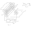
- number 1 indicates, overall, a calender with an inverted L arrangement, into which a film 2 is fed.
- Roller 3 of the calender 1 is designed to expand and contract radially due to thermal action.
- Device 4 is provided to adjust the diameter profile of the roller 3 according to the transverse thickness profile of the film 2 coming out of the calender 1.
- the said device 4 is provided with a number of nozzles 5, communicating with a pressurised air source 6, which direct jets of air onto the roller 3.
- the nozzles 5 are arranged so that the air jets are directed onto adjacent sectors 31 of the roller 3 throughout its length; several nozzles can be directed at the same sector of the roller 3, in particular at the ends of the roller where natural cooling is quicker.
- Means 7 are provided to selectively regulate the temperature of the air coming out of each nozzle and means 8 are provided to selectively regulate the air flow rate of each nozzle 5.
- Means 9 provide an electrical signal, corresponding to the transverse thickness profile of the film 2 coming out of the calender 1, which, via a regulation and control system 10, controls the means 7 for selectively adjusting the temperature of the air coming out of each nozzle and the means 8 for selectively adjusting the air flow rate of each nozzle.
- the device operates as follows:
- the pressurised air source 6 comprises a stainless steel seal manifold 61, fed by a fan (not shown).
- the manifold 61 is arranged parallel to the roller 3 and the nozzles 5 are provided on one face 611 with a half-bearing shape.
- the depth of the air space is preferably 25-30 mm.
- nozzles 5 can be provided on the same sector 51, in particular at the ends of the roller 3 where natural cooling of the roller occurs more rapidly.
- the nozzles 5 are suitably arranged so that they are directed at the sectors of the roller with a width of 75 mm; assuming that the roller is 1800 mm long, then there will be at least 24 nozzles.
- the working pressure inside the manifold 61 is substantially constant and is preferably between 15 and 20 mbars.
- a drain valve can be provided (not shown).
- the air inside manifold 61 is at a substantially constant temperature, preferably at ambient value.
- the maximum flow rate of each nozzle is preferably 0.4 m 3 /min.
- the nozzles 5 are tubular-shaped and the devices 7 for selectively adjusting the air temperature consist of electrical resistances 7 arranged inside the nozzles 5.
- the minimum temperature of the air jet is to that of the manifold supply temperature, while the maximum temperature that can be reached is approximately 270°C, and the electrical power of the resistance of each nozzle can reach 1600 Watts.
- the nozzles 5 are arranged inside the manifold 61 and are provided with adequate thermal insulation to prevent the resistance affecting the temperature inside the manifold.
- the devices 8, for adjusting the air jet flow rate of the nozzles 5, consist of shutters 81, controlled by a stepper motor 82, which regulate the inlet section of each nozzle 5.
Landscapes
- Casting Or Compression Moulding Of Plastics Or The Like (AREA)
- Paper (AREA)
- Shaping Of Tube Ends By Bending Or Straightening (AREA)
Abstract
- means (9) for sensing the transverse thickness profile of a film (2) coming out of a calender (1) and for providing a signal corresponding to the thickness of the film (2);
- a pressurised air source (6);
- a number of nozzles (5), communicating with the pressurised air source (6), designed to direct the air towards the roller (3);
- means (7) for selectively adjusting the temperature of the air coming out of each nozzle (5);
- means (8) for selectively regulating the flow rate of the air coming out of each nozzle (5);
- means (10) for operating said means (7) and (8) for selectively adjusting the temperature and air flow rate of each nozzle according to the signal corresponding to the thickness of the film coming out of the calender.
Description
- Figure 1 is a schematic view of a calendering system provided with a device for adjusting the diameter profile of a roller according to the invention;
- figure 2 shows the transverse thickness profile measured on a calendered film and the difference with respect to the set profile;
- figure 3 is a schematic axonometric drawing of the adjustment device in accordance with the invention;
- figure 4 is a schematic
- where the roller diameter profile does not require adjustment, the air flow rate is interrupted;
- where the roller diameter profile has to be reduced, the air is not heated and the air flow rate is regulated according to the difference between the thickness measured and the thickness set, and
- where the roller diameter profile has to be increased, the air flow rate is set at a maximum and the air is heated according to the difference between the thickness measured and the thickness set.
Claims (5)
- Device for adjusting the diameter profile of a roller (3) of a calender (1), comprising:means (9) for sensing the transverse thickness profile of a film (2) coming out of a calender (1) and for providing a signal corresponding to the thickness of the film (2);a pressurised air source (6);a number of nozzles (5), communicating with the pressurised air source (6), designed to direct the air towards the roller (3);means (7) for selectively adjusting the temperature of the air coming out of each nozzle (5);means (8) for selectively regulating the flow rate of the air coming out of each nozzle (5);means (10) for operating said means (7) and (8) for selectively adjusting the temperature and air flow rate of each nozzle according to the signal corresponding to the thickness of the film coming out of the calender.
- Device, according to claim 1, in which means (63) are provided to maintain the pressure of the pressurised air source (6) constant as the air flow rate varies.
- Device, according to claim 1 or 2, in which said means (7) for selectively adjusting the temperature of the air coming out of each nozzle (5), consist of electrical resistances positioned inside each nozzle and/or before the inlet of each nozzle (5).
- Device, according to claim 1 or 2 or 3 in which said means (8) for selectively regulating the air flow rate of each nozzle (5) consist of shutters (81) controlled by a stepper motor (82).
- Procedure for adjusting the diameter profile of a calender roller, comprising the following steps:sensing the transverse thickness profile of the film (2) coming out of the calender (1) and provide a signal corresponding to the film thickness;provide a number of air jets directed towards the roller (3), selectively adjusting the temperature and air flow rate of each jet so that:a) where the diameter profile of the roller does not require adjustment the air flow rate is interrupted;b) where the diameter profile of the roller has to be reduced, the air is not heated and the flow rate is regulated according to the difference between the thickness measured and the thickness set,c) where the diameter profile of the roller has to be increased, the air flow rate is at maximum and the air is heated according to the difference between the thickness measured and the thickness set.
Applications Claiming Priority (2)
| Application Number | Priority Date | Filing Date | Title |
|---|---|---|---|
| IT2001MI001660A ITMI20011660A1 (en) | 2001-07-31 | 2001-07-31 | DEVICE AND PROCEDURE FOR ADJUSTING THE DIAMETER PROFILE OF A CALENDER ROLL |
| ITMI20011660 | 2001-07-31 |
Publications (3)
| Publication Number | Publication Date |
|---|---|
| EP1281810A2 true EP1281810A2 (en) | 2003-02-05 |
| EP1281810A3 EP1281810A3 (en) | 2004-01-02 |
| EP1281810B1 EP1281810B1 (en) | 2006-06-14 |
Family
ID=11448190
Family Applications (1)
| Application Number | Title | Priority Date | Filing Date |
|---|---|---|---|
| EP02016241A Expired - Lifetime EP1281810B1 (en) | 2001-07-31 | 2002-07-22 | Device and procedure for adjusting the diameter profile of a calender roller |
Country Status (4)
| Country | Link |
|---|---|
| EP (1) | EP1281810B1 (en) |
| DE (1) | DE60212269T2 (en) |
| ES (1) | ES2266355T3 (en) |
| IT (1) | ITMI20011660A1 (en) |
Family Cites Families (1)
| Publication number | Priority date | Publication date | Assignee | Title |
|---|---|---|---|---|
| US3770578A (en) * | 1971-05-12 | 1973-11-06 | Midland Ross Corp | Method for controlling caliper |
-
2001
- 2001-07-31 IT IT2001MI001660A patent/ITMI20011660A1/en unknown
-
2002
- 2002-07-22 ES ES02016241T patent/ES2266355T3/en not_active Expired - Lifetime
- 2002-07-22 DE DE60212269T patent/DE60212269T2/en not_active Expired - Fee Related
- 2002-07-22 EP EP02016241A patent/EP1281810B1/en not_active Expired - Lifetime
Also Published As
| Publication number | Publication date |
|---|---|
| EP1281810B1 (en) | 2006-06-14 |
| DE60212269D1 (en) | 2006-07-27 |
| EP1281810A3 (en) | 2004-01-02 |
| ITMI20011660A1 (en) | 2003-01-31 |
| DE60212269T2 (en) | 2007-05-24 |
| ES2266355T3 (en) | 2007-03-01 |
| ITMI20011660A0 (en) | 2001-07-31 |
Similar Documents
| Publication | Publication Date | Title |
|---|---|---|
| FI82275C (en) | FOERFARANDE OCH ANORDNING FOER REGLERING AV TJOCKLEKEN HOS ETT BANMATERIAL SOM GAOR GENOM EN NIP. | |
| CA1242099A (en) | Hot air calender roll controller | |
| CA2008733C (en) | Cross-directional smoothness controller and method of using same | |
| CN1215000C (en) | Method and apparatus of heating glass plate in tempering furnace equipped with roller | |
| KR20020029748A (en) | Improved flat glass annealing lehrs | |
| US4658716A (en) | Infrared heating calender roll controller | |
| KR102121677B1 (en) | Preheating and thermal control of work rolls in metal rolling process and its control system | |
| US6282923B1 (en) | Heating glass sheets in tempering furnace | |
| US4823688A (en) | Calendering apparatus using inductive heating for hot-calendering a paper web | |
| KR950009501B1 (en) | Air heater for a calender roll diameter controller | |
| US4671173A (en) | Steam jet calender controller with condensate suction | |
| EP1281810B1 (en) | Device and procedure for adjusting the diameter profile of a calender roller | |
| US4685389A (en) | Hot air calender roll controller | |
| US7897075B2 (en) | Calender gap control | |
| CA2116603C (en) | Steam spray tube and process for adjusting gloss and/or smoothness of a moving web of material | |
| US4748906A (en) | Air shower apparatus and method | |
| CA2315822C (en) | Heating system for compressive shrinkage machines | |
| EP2141132B1 (en) | Furnace | |
| US4867054A (en) | Caliper control system | |
| US6010323A (en) | Vacuum pressure forming apparatus and vacuum pressure forming method | |
| FI111864B (en) | Method of calendering paper web and calender applying the procedure | |
| US6881362B2 (en) | Process and apparatus for the relaxation of interlayer sheet | |
| WO1990014216A1 (en) | Calendering control system | |
| US6000328A (en) | Gloss control system using air jets | |
| JPH0375676B2 (en) |
Legal Events
| Date | Code | Title | Description |
|---|---|---|---|
| PUAI | Public reference made under article 153(3) epc to a published international application that has entered the european phase |
Free format text: ORIGINAL CODE: 0009012 |
|
| AK | Designated contracting states |
Designated state(s): AT BE BG CH CY CZ DE DK EE ES FI FR GB GR IE IT LI LU MC NL PT SE SK TR |
|
| AX | Request for extension of the european patent |
Extension state: AL LT LV MK RO SI |
|
| PUAL | Search report despatched |
Free format text: ORIGINAL CODE: 0009013 |
|
| AK | Designated contracting states |
Kind code of ref document: A3 Designated state(s): AT BE BG CH CY CZ DE DK EE ES FI FR GB GR IE IT LI LU MC NL PT SE SK TR |
|
| AX | Request for extension of the european patent |
Extension state: AL LT LV MK RO SI |
|
| RIC1 | Information provided on ipc code assigned before grant |
Ipc: 7D 21F 7/06 A |
|
| 17P | Request for examination filed |
Effective date: 20040518 |
|
| AKX | Designation fees paid |
Designated state(s): DE ES FR GB IT |
|
| GRAP | Despatch of communication of intention to grant a patent |
Free format text: ORIGINAL CODE: EPIDOSNIGR1 |
|
| GRAS | Grant fee paid |
Free format text: ORIGINAL CODE: EPIDOSNIGR3 |
|
| GRAA | (expected) grant |
Free format text: ORIGINAL CODE: 0009210 |
|
| AK | Designated contracting states |
Kind code of ref document: B1 Designated state(s): DE ES FR GB IT |
|
| REG | Reference to a national code |
Ref country code: GB Ref legal event code: FG4D |
|
| REF | Corresponds to: |
Ref document number: 60212269 Country of ref document: DE Date of ref document: 20060727 Kind code of ref document: P |
|
| ET | Fr: translation filed | ||
| REG | Reference to a national code |
Ref country code: ES Ref legal event code: FG2A Ref document number: 2266355 Country of ref document: ES Kind code of ref document: T3 |
|
| PLBE | No opposition filed within time limit |
Free format text: ORIGINAL CODE: 0009261 |
|
| STAA | Information on the status of an ep patent application or granted ep patent |
Free format text: STATUS: NO OPPOSITION FILED WITHIN TIME LIMIT |
|
| 26N | No opposition filed |
Effective date: 20070315 |
|
| REG | Reference to a national code |
Ref country code: FR Ref legal event code: ST Effective date: 20070531 |
|
| PGFP | Annual fee paid to national office [announced via postgrant information from national office to epo] |
Ref country code: ES Payment date: 20070709 Year of fee payment: 6 |
|
| PGFP | Annual fee paid to national office [announced via postgrant information from national office to epo] |
Ref country code: DE Payment date: 20070731 Year of fee payment: 6 |
|
| REG | Reference to a national code |
Ref country code: FR Ref legal event code: RN |
|
| PGFP | Annual fee paid to national office [announced via postgrant information from national office to epo] |
Ref country code: GB Payment date: 20070716 Year of fee payment: 6 |
|
| PGFP | Annual fee paid to national office [announced via postgrant information from national office to epo] |
Ref country code: IT Payment date: 20070723 Year of fee payment: 6 |
|
| REG | Reference to a national code |
Ref country code: FR Ref legal event code: D3 |
|
| PG25 | Lapsed in a contracting state [announced via postgrant information from national office to epo] |
Ref country code: FR Free format text: LAPSE BECAUSE OF NON-PAYMENT OF DUE FEES Effective date: 20060731 |
|
| PGFP | Annual fee paid to national office [announced via postgrant information from national office to epo] |
Ref country code: FR Payment date: 20070720 Year of fee payment: 6 |
|
| GBPC | Gb: european patent ceased through non-payment of renewal fee |
Effective date: 20080722 |
|
| PG25 | Lapsed in a contracting state [announced via postgrant information from national office to epo] |
Ref country code: DE Free format text: LAPSE BECAUSE OF NON-PAYMENT OF DUE FEES Effective date: 20090203 |
|
| REG | Reference to a national code |
Ref country code: FR Ref legal event code: ST Effective date: 20090331 |
|
| PG25 | Lapsed in a contracting state [announced via postgrant information from national office to epo] |
Ref country code: GB Free format text: LAPSE BECAUSE OF NON-PAYMENT OF DUE FEES Effective date: 20080722 |
|
| PG25 | Lapsed in a contracting state [announced via postgrant information from national office to epo] |
Ref country code: IT Free format text: LAPSE BECAUSE OF NON-PAYMENT OF DUE FEES Effective date: 20080722 |
|
| REG | Reference to a national code |
Ref country code: ES Ref legal event code: FD2A Effective date: 20080723 |
|
| PG25 | Lapsed in a contracting state [announced via postgrant information from national office to epo] |
Ref country code: ES Free format text: LAPSE BECAUSE OF NON-PAYMENT OF DUE FEES Effective date: 20080723 |
|
| PG25 | Lapsed in a contracting state [announced via postgrant information from national office to epo] |
Ref country code: FR Free format text: LAPSE BECAUSE OF NON-PAYMENT OF DUE FEES Effective date: 20080731 |