EP1281741A1 - Sealant for prevention of blowout, tubeless tire, and tire tube - Google Patents
Sealant for prevention of blowout, tubeless tire, and tire tube Download PDFInfo
- Publication number
- EP1281741A1 EP1281741A1 EP01917627A EP01917627A EP1281741A1 EP 1281741 A1 EP1281741 A1 EP 1281741A1 EP 01917627 A EP01917627 A EP 01917627A EP 01917627 A EP01917627 A EP 01917627A EP 1281741 A1 EP1281741 A1 EP 1281741A1
- Authority
- EP
- European Patent Office
- Prior art keywords
- sealant
- tire
- chamber
- viscosity
- vehicle
- Prior art date
- Legal status (The legal status is an assumption and is not a legal conclusion. Google has not performed a legal analysis and makes no representation as to the accuracy of the status listed.)
- Granted
Links
- AQUSHMBHIVJHCA-UHFFFAOYSA-N CCCCC(CC1)CCC1C(CC1)CC1C(C1)CC1C1CCC1 Chemical compound CCCCC(CC1)CCC1C(CC1)CC1C(C1)CC1C1CCC1 AQUSHMBHIVJHCA-UHFFFAOYSA-N 0.000 description 1
Images


Classifications
-
- B—PERFORMING OPERATIONS; TRANSPORTING
- B29—WORKING OF PLASTICS; WORKING OF SUBSTANCES IN A PLASTIC STATE IN GENERAL
- B29C—SHAPING OR JOINING OF PLASTICS; SHAPING OF MATERIAL IN A PLASTIC STATE, NOT OTHERWISE PROVIDED FOR; AFTER-TREATMENT OF THE SHAPED PRODUCTS, e.g. REPAIRING
- B29C73/00—Repairing of articles made from plastics or substances in a plastic state, e.g. of articles shaped or produced by using techniques covered by this subclass or subclass B29D
- B29C73/16—Auto-repairing or self-sealing arrangements or agents
- B29C73/22—Auto-repairing or self-sealing arrangements or agents the article containing elements including a sealing composition, e.g. powder being liberated when the article is damaged
-
- B—PERFORMING OPERATIONS; TRANSPORTING
- B29—WORKING OF PLASTICS; WORKING OF SUBSTANCES IN A PLASTIC STATE IN GENERAL
- B29D—PRODUCING PARTICULAR ARTICLES FROM PLASTICS OR FROM SUBSTANCES IN A PLASTIC STATE
- B29D30/00—Producing pneumatic or solid tyres or parts thereof
- B29D30/06—Pneumatic tyres or parts thereof (e.g. produced by casting, moulding, compression moulding, injection moulding, centrifugal casting)
- B29D30/0681—Parts of pneumatic tyres; accessories, auxiliary operations
- B29D30/0685—Incorporating auto-repairing or self-sealing arrangements or agents on or into tyres
-
- B—PERFORMING OPERATIONS; TRANSPORTING
- B60—VEHICLES IN GENERAL
- B60C—VEHICLE TYRES; TYRE INFLATION; TYRE CHANGING; CONNECTING VALVES TO INFLATABLE ELASTIC BODIES IN GENERAL; DEVICES OR ARRANGEMENTS RELATED TO TYRES
- B60C19/00—Tyre parts or constructions not otherwise provided for
- B60C19/12—Puncture preventing arrangements
-
- B—PERFORMING OPERATIONS; TRANSPORTING
- B29—WORKING OF PLASTICS; WORKING OF SUBSTANCES IN A PLASTIC STATE IN GENERAL
- B29D—PRODUCING PARTICULAR ARTICLES FROM PLASTICS OR FROM SUBSTANCES IN A PLASTIC STATE
- B29D30/00—Producing pneumatic or solid tyres or parts thereof
- B29D30/06—Pneumatic tyres or parts thereof (e.g. produced by casting, moulding, compression moulding, injection moulding, centrifugal casting)
- B29D30/0681—Parts of pneumatic tyres; accessories, auxiliary operations
- B29D30/0685—Incorporating auto-repairing or self-sealing arrangements or agents on or into tyres
- B29D2030/0686—Incorporating sealants on or into tyres not otherwise provided for; auxiliary operations therefore, e.g. preparation of the tyre
- B29D2030/0698—Incorporating sealants on or into tyres not otherwise provided for; auxiliary operations therefore, e.g. preparation of the tyre the sealant being applied by injection, e.g. introducing the sealant through a hole
-
- B—PERFORMING OPERATIONS; TRANSPORTING
- B29—WORKING OF PLASTICS; WORKING OF SUBSTANCES IN A PLASTIC STATE IN GENERAL
- B29K—INDEXING SCHEME ASSOCIATED WITH SUBCLASSES B29B, B29C OR B29D, RELATING TO MOULDING MATERIALS OR TO MATERIALS FOR MOULDS, REINFORCEMENTS, FILLERS OR PREFORMED PARTS, e.g. INSERTS
- B29K2105/00—Condition, form or state of moulded material or of the material to be shaped
- B29K2105/0094—Condition, form or state of moulded material or of the material to be shaped having particular viscosity
-
- B—PERFORMING OPERATIONS; TRANSPORTING
- B29—WORKING OF PLASTICS; WORKING OF SUBSTANCES IN A PLASTIC STATE IN GENERAL
- B29L—INDEXING SCHEME ASSOCIATED WITH SUBCLASS B29C, RELATING TO PARTICULAR ARTICLES
- B29L2030/00—Pneumatic or solid tyres or parts thereof
-
- Y—GENERAL TAGGING OF NEW TECHNOLOGICAL DEVELOPMENTS; GENERAL TAGGING OF CROSS-SECTIONAL TECHNOLOGIES SPANNING OVER SEVERAL SECTIONS OF THE IPC; TECHNICAL SUBJECTS COVERED BY FORMER USPC CROSS-REFERENCE ART COLLECTIONS [XRACs] AND DIGESTS
- Y10—TECHNICAL SUBJECTS COVERED BY FORMER USPC
- Y10T—TECHNICAL SUBJECTS COVERED BY FORMER US CLASSIFICATION
- Y10T152/00—Resilient tires and wheels
- Y10T152/10—Tires, resilient
- Y10T152/10495—Pneumatic tire or inner tube
- Y10T152/10666—Automatic sealing of punctures [e.g., self-healing, etc.]
- Y10T152/10675—Using flowable coating or composition
-
- Y—GENERAL TAGGING OF NEW TECHNOLOGICAL DEVELOPMENTS; GENERAL TAGGING OF CROSS-SECTIONAL TECHNOLOGIES SPANNING OVER SEVERAL SECTIONS OF THE IPC; TECHNICAL SUBJECTS COVERED BY FORMER USPC CROSS-REFERENCE ART COLLECTIONS [XRACs] AND DIGESTS
- Y10—TECHNICAL SUBJECTS COVERED BY FORMER USPC
- Y10T—TECHNICAL SUBJECTS COVERED BY FORMER US CLASSIFICATION
- Y10T152/00—Resilient tires and wheels
- Y10T152/10—Tires, resilient
- Y10T152/10495—Pneumatic tire or inner tube
- Y10T152/10666—Automatic sealing of punctures [e.g., self-healing, etc.]
- Y10T152/10675—Using flowable coating or composition
- Y10T152/10684—On inner surface of tubeless tire
-
- Y—GENERAL TAGGING OF NEW TECHNOLOGICAL DEVELOPMENTS; GENERAL TAGGING OF CROSS-SECTIONAL TECHNOLOGIES SPANNING OVER SEVERAL SECTIONS OF THE IPC; TECHNICAL SUBJECTS COVERED BY FORMER USPC CROSS-REFERENCE ART COLLECTIONS [XRACs] AND DIGESTS
- Y10—TECHNICAL SUBJECTS COVERED BY FORMER USPC
- Y10T—TECHNICAL SUBJECTS COVERED BY FORMER US CLASSIFICATION
- Y10T152/00—Resilient tires and wheels
- Y10T152/10—Tires, resilient
- Y10T152/10495—Pneumatic tire or inner tube
- Y10T152/10666—Automatic sealing of punctures [e.g., self-healing, etc.]
- Y10T152/10675—Using flowable coating or composition
- Y10T152/10702—Using flowable coating or composition within or part of construction of inflating inner tube
Definitions
- the present invention relates to a puncture-preventing sealant which is filled in a sealant chamber defined to extend along an outer periphery of an air chamber in a tire, as well as to a tubeless tire and a tire tube using such puncture-preventing sealant.
- a tire using such a puncture-preventing sealant is already known from Japanese Patent Application Laid-open No.10-71806, for example.
- the known puncture-preventing sealant has a viscosity set in a range of 20 to 23 dPa•s, and a thixotropy index set in a range of 5.5 to 5.8.
- the present invention has been accomplished in view of the circumstances described above, and it is an object of the present invention to ensure that the puncture-preventing sealant has such a nature that the sealant is easy to flow due to a low viscosity during traveling of a vehicle, and is difficult to flow due to a high viscosity when it is left to stand, while ensuring that the puncture-preventing sealant has a sealability equivalent to that of the known sealant, whereby the balanceability can be enhanced.
- a puncture-preventing sealant which is filled in a sealant chamber defined to extend along an outer periphery of an air chamber in a tire, the sealant having a viscosity in a range of 25 to 35 dPa ⁇ s. and a thixotropy index in a range of 6.5 to 11.0.
- the viscosity of the puncture-preventing sealant is in the range of 25 to 35 dPa ⁇ s, and the thixotropy index of the sealant is in the range of 6.5 to 11.0. Therefore, when the tire is being rotated by traveling of a vehicle, the viscosity of the sealant is reduced by a stirring action caused by a vibration or a centrifugal force, whereby the sealant can be diffused uniformly within the sealant chamber. When the vehicle has been stopped, resulting in the elimination of stirring action, the viscosity of the sealant is increased, whereby the sealant is maintained in a state in which it has been diffused uniformly without flowing downwards within the sealant chamber by gravitation. Therefore, a balanced state can be maintained, and even when the vehicle travels at a high speed after lapse of a long time in the stopped state of the vehicle, the generation of a vibration and a noise can be prevented.
- the sealant chamber having a radial thickness in a range of 1.2 ⁇ 0.3 mm.
- the radial thickness of the sealant chamber is set in the range of 1.2 ⁇ 0.3 mm. Therefore, it is possible to prevent the thickness from being too large, causing the sealant to flow downwards under the action of the force of gravity, resulting in the balance loss, when the tire is left to stand, and to prevent the thickness from being too small, causing the sealability for a puncture to be reduced, or to prevent the sealant from being difficult to diffuse uniformly within the sealant chamber.
- both of the balanceability and the sealability of the tire can be reconciled to the maximum.
- the sealant chamber having a radial thickness in a range of 1.2 ⁇ 0.3 mm.
- the radial thickness of the sealant chamber is in the range of 1.2 ⁇ 0.3 mm. Therefore, it is possible to prevent the thickness from being too large, causing the sealant to flow downwards by gravitation, resulting in the balance loss, when the tire is left to stand, and to prevent the thickness from being too small, causing the sealability for a puncture to be reduced, or to prevent the sealant from being difficult to diffuse uniformly within the sealant chamber. Thus, both of the balanceability and the sealability of the tire can be reconciled to the maximum.
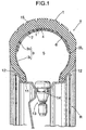
- Fig.1 shows an embodiment in which a sealant according to the present invention is utilized in a tubeless tire T.
- the tubeless tire T is mounted on a rim R of a wheel, and comprises a tire body 1 and an inner liner 2L adhered by vulcanization to the inside of the tire body 1.
- the inner liner 2L includes a peripheral wall 3, which is formed into a U-shape in section and has air-chamber peripheral wall portions 3i, 3i located on the radially inner side of the tire T, and a sealant-chamber peripheral wall portion 30 located on the radially outer side of the tire T.
- Air is filled in an air chamber 5 substantially circular in section and defined between the air-chamber peripheral wall portions 3i, 3i and the partition wall 4, and a gelled sealant 7 is filled in a sealant chamber 6 substantially arcuate in section and defined between the sealant-chamber peripheral wall portion 3o and the partition wall 4.
- the rim R includes an annular rim body 11 extending circumferentially of the tire T, and a pair of flange portions 12, 12 extending radially outwards from widthwise opposite ends of the rim body 11 to retain an inner periphery of the tire body 1.
- a pneumatic valve 13 for filling air into the air chamber 5 defined inside the inner liner 2L is supported to extend through a pneumatic valve-mounting portion 14 formed at circumferentially one point on the rim body 11.
- Fig.2 shows an embodiment in which a sealant 7 according to the present invention is utilized in a tube-incorporated tire T.
- the tube-incorporated tire T includes a tire tube 2T corresponding to the inner liner 2L of the above-described tubeless tire T.
- the tire tube 2T is capable of being mounted and removed on and from the tire body 1, and includes air-chamber peripheral wall portions 3i, a sealant-chamber peripheral wall portion 3o and a partition wall 4. as does the inner liner 2L.
- An air chamber 5 is defined between the air-chamber peripheral wall portions 3i and the partition wall 4, so that air is filled in the air chamber 5, and a sealant chamber 6 is defined between the sealant-chamber peripheral wall portion 3o and the partition wall 4, so that a sealant 7 is filled in the sealant chamber 6.
- a pneumatic valve 13 is mounted in the air-chamber peripheral wall portions 3i of the tire tube 2T and supported to extend through a pneumatic valve-mounting portion 14 formed at circumferentially one point on the rim body 11.
- the sealant chamber 6 in the inner liner 2L or the tire tube 2T is maintained in a shape extending along the inside of a tread 15 by an air pressure in the air chamber 5. Therefore, even if the tire body 1 is punctured radially or sideways by a nail or the like, the sealant 7 fills the puncture immediately to repair it, thereby retarding the leakage of the air from the air chamber 5.
- the sealant 7 is retained in the sealant chamber 6 and cannot flow out of the sealant chamber 6 into the air chamber 5, and hence, the pneumatic valve 13, a pressure gauge applied to the pneumatic valve 13 and the like cannot be clogged.
- the sealant 7 filled in the sealant chamber 6 will be described below.
- the viscosity of the sealant 7 in the present embodiment is reduced by a stirring action provided by a vibration transmitted from a road surface or by a centrifugal force of the sealant 7, whereby the sealant 7 can be diffused uniformly in the annular sealant chamber 6 to provide a static balance and a dynamic balance for wheels.
- the viscosity of the sealant 7 is increased, whereby the sealant 7 is maintained in a state in which it has been diffused uniformly in the sealant chamber 6 without flowing downwards in the sealant chamber 6 by gravitation. Therefore, when the vehicle is traveling at a high speed, the same state as in the balancing can be reproduced.
- Constituent % By weight Water 65 Propylene glycol 30 Thickener 2.0 Nylon fiber 0.5 Cotton fiber 1.4 Ceramic powder 0.5 Dye 0.1
- constituents of the sealant 7 in the present embodiment are 56 % by weight of water, 30 % by weight of propylene glycol, 2.0 % by weight of a thickener, 0.5 % by weight of a nylon fiber, 1.4 % by weight of a cotton fiber, 0.5 % by weight of a ceramic powder, and 0.1 % by weight of a dye.
- Prior art Embodiment Viscosity 23 30 Thixotropy index 5.8 7.02 Balanceability ⁇ ⁇ Sealability for puncture ⁇ - ⁇ ⁇
- the prior art sealant has a viscosity of 20 dPa ⁇ s and a thixotropy index of 5.8, while the sealant 7 in the present embodiment has a viscosity of 30 dPa ⁇ s and a thixotropy index of 7.02.
- the thixotropy index is a value determined according to JIS K(6800), and the viscosity is a value measured by a VT-04 type viscometer made by LYON.
- the sealant 7 in the present embodiment has the thixotropy index larger than that of the prior art sealant and hence, shows a remarked tendency to reduce in viscosity during traveling of the vehicle and to increase in viscosity when the sealant is being left to stand.
- the puncture sealability of the sealant 7 in the present embodiment is also superior to that of the prior art sealant due to the constituent of the sealant 7 shown in Table 1.
- the unbalance amount is varied with an increase in number of days on which the sealant has been left to stand after traveling of the vehicle, but in the tire T using the sealant 7 in the present embodiment having the higher thixotropy index, the unbalance amount is maintained stably, even if the number of days on which the sealant has been left to stand after traveling of the vehicle is increased.
- the sealant chamber 6 has a radial thickness t set in a range of 1.2 ⁇ 0.3 mm and thus, it is possible to exhibit the balanceability and the puncture sealability of the tire T to the maximum.
- the viscosity of the sealant 7 is 30 dPa•s, and the thixotropy index is 7.02, but if the viscosity is set in a range of 25 to 35 dPa•s, and the thixotropy index is in a range of 6.5 to 11.0, a desired effect can be provided.
Landscapes
- Engineering & Computer Science (AREA)
- Mechanical Engineering (AREA)
- Tires In General (AREA)
- Sealing Material Composition (AREA)
Abstract
Description
| Constituent | % By weight |
| Water | 65 |
| | 30 |
| Thickener | 2.0 |
| Nylon fiber | 0.5 |
| Cotton fiber | 1.4 |
| Ceramic powder | 0.5 |
| Dye | 0.1 |
| Prior art | Embodiment | |
| Viscosity | 23 | 30 |
| Thixotropy index | 5.8 | 7.02 |
| Balanceability | × | ○ |
| Sealability for puncture | Δ-○ | ○ |
Claims (3)
- A puncture-preventing sealant which is filled in a sealant chamber defined to extend along an outer periphery of an air chamber in a tire, said sealant having a viscosity in a range of 25 to 35 dPa•s, and a thixotropy index in a range of 6.5 to 11.0.
- A tubeless tire using a puncture-preventing sealant according to claim 1, said sealant chamber having a radial thickness in a range of 1.2 ± 0.3 mm.
- A tire tube using a puncture-preventing sealant according to claim 1, said sealant chamber having a radial thickness in a range of 1.2 ± 0.3 mm.
Applications Claiming Priority (3)
| Application Number | Priority Date | Filing Date | Title |
|---|---|---|---|
| JP2000108019A JP3943799B2 (en) | 2000-04-05 | 2000-04-05 | Anti-puncture sealant, tubeless tires and tire tubes |
| JP2000108019 | 2000-04-05 | ||
| PCT/JP2001/002664 WO2001077251A1 (en) | 2000-04-05 | 2001-03-29 | Sealant for prevention of blowout, tubeless tire, and tire tube |
Publications (3)
| Publication Number | Publication Date |
|---|---|
| EP1281741A1 true EP1281741A1 (en) | 2003-02-05 |
| EP1281741A4 EP1281741A4 (en) | 2003-04-02 |
| EP1281741B1 EP1281741B1 (en) | 2004-05-06 |
Family
ID=18620936
Family Applications (1)
| Application Number | Title | Priority Date | Filing Date |
|---|---|---|---|
| EP01917627A Expired - Lifetime EP1281741B1 (en) | 2000-04-05 | 2001-03-29 | Sealant for prevention of blowout, tubeless tire, and tire tube |
Country Status (12)
| Country | Link |
|---|---|
| US (1) | US7316253B2 (en) |
| EP (1) | EP1281741B1 (en) |
| JP (1) | JP3943799B2 (en) |
| KR (1) | KR100513905B1 (en) |
| CN (1) | CN100387671C (en) |
| AR (1) | AR028909A1 (en) |
| BR (1) | BR0109865B1 (en) |
| DE (1) | DE60103148T2 (en) |
| ES (1) | ES2220747T3 (en) |
| MY (1) | MY124518A (en) |
| TW (1) | TW580463B (en) |
| WO (1) | WO2001077251A1 (en) |
Families Citing this family (9)
| Publication number | Priority date | Publication date | Assignee | Title |
|---|---|---|---|---|
| US7073550B2 (en) * | 2004-03-17 | 2006-07-11 | The Goodyear Tire & Rubber Company | Pneumatic tire having built-in colored sealant layer and preparation thereof |
| JP4507970B2 (en) * | 2005-04-25 | 2010-07-21 | 横浜ゴム株式会社 | Low noise pneumatic tire |
| JP4299813B2 (en) * | 2005-07-20 | 2009-07-22 | 住友ゴム工業株式会社 | Pneumatic tire |
| FR2895312B1 (en) * | 2005-12-23 | 2009-11-27 | Michelin Soc Tech | LARGE DIMENSION FOAM CHAMBER FOR PNEUMATIC. |
| BRPI0816494A2 (en) * | 2007-10-09 | 2015-02-24 | Trydel Res Pty Ltd | IMPROVED SEALING COMPOSITION |
| US8646501B2 (en) | 2010-11-11 | 2014-02-11 | The Goodyear Tire & Rubber Company | Puncture sealant laminate |
| CN104669947A (en) * | 2013-11-28 | 2015-06-03 | 杜永财 | Tire anti-piercing pad |
| KR101664177B1 (en) | 2014-11-20 | 2016-10-11 | 장철환 | Tubeless tire and wheel reducing hydro planing |
| TWI741200B (en) * | 2018-07-20 | 2021-10-01 | 正新橡膠工業股份有限公司 | Tire noise reduction device |
Family Cites Families (18)
| Publication number | Priority date | Publication date | Assignee | Title |
|---|---|---|---|---|
| CA987211A (en) * | 1973-05-03 | 1976-04-13 | Roy J. Emerson | Puncture sealing means for pneumatic tires |
| GB1541382A (en) * | 1976-06-07 | 1979-02-28 | Yokohama Rubber Co Ltd | Puncture sealant for a tubeless pneumatic tyre |
| JPS548307A (en) * | 1977-06-21 | 1979-01-22 | Bridgestone Corp | Method of repairing puncture |
| JPS5763374A (en) * | 1980-09-30 | 1982-04-16 | Deii Ando Bii Chem Corp | Liquid composition for air-containing tire sealant |
| US4665963A (en) | 1983-06-01 | 1987-05-19 | Polysar Limited | Pneumatic tire inner liner having puncture sealing characteristics |
| GB2236534B (en) * | 1989-09-29 | 1993-02-03 | Day Jiann Jinn | A tyre |
| US5772747A (en) * | 1994-08-01 | 1998-06-30 | Peter Chun | Tire sealant composition |
| WO1996005048A1 (en) * | 1994-08-12 | 1996-02-22 | Terence Dowel | Tyre puncture sealant compositions |
| US6013697A (en) * | 1995-10-31 | 2000-01-11 | Glaser-True Bike Route, Ltd. | Tire sealant composition |
| US5856376A (en) * | 1996-03-29 | 1999-01-05 | Nch Corporation | Tire puncture sealant |
| JP3497326B2 (en) * | 1996-06-27 | 2004-02-16 | 本田技研工業株式会社 | Puncture prevention sealant |
| JPH1017851A (en) * | 1996-07-03 | 1998-01-20 | Three Bond Co Ltd | Tire puncture preventive |
| US5785749A (en) * | 1997-02-19 | 1998-07-28 | Southern Clay Products, Inc. | Method for producing rheological additives and coating compositions incorporating same |
| US6646354B2 (en) * | 1997-08-22 | 2003-11-11 | Micron Technology, Inc. | Adhesive composition and methods for use in packaging applications |
| JP3912636B2 (en) * | 1998-03-04 | 2007-05-09 | 本田技研工業株式会社 | Tire tube manufacturing equipment |
| ES2230832T3 (en) * | 1998-03-16 | 2005-05-01 | Honda Giken Kogyo Kabushiki Kaisha | TIRES MANUFACTURING PROCEDURE WITH SEALING AGENT AND TIRES WITH SEALING AGENT. |
| JP2000104042A (en) * | 1998-09-30 | 2000-04-11 | Three Bond Co Ltd | Tire puncture preventive |
| US20020077391A1 (en) * | 2000-12-15 | 2002-06-20 | Mcinnes Robert P. | Fibers for tire sealant composition |
-
2000
- 2000-04-05 JP JP2000108019A patent/JP3943799B2/en not_active Expired - Fee Related
-
2001
- 2001-03-29 ES ES01917627T patent/ES2220747T3/en not_active Expired - Lifetime
- 2001-03-29 BR BRPI0109865-9A patent/BR0109865B1/en not_active IP Right Cessation
- 2001-03-29 CN CNB018082130A patent/CN100387671C/en not_active Expired - Fee Related
- 2001-03-29 EP EP01917627A patent/EP1281741B1/en not_active Expired - Lifetime
- 2001-03-29 WO PCT/JP2001/002664 patent/WO2001077251A1/en not_active Ceased
- 2001-03-29 DE DE60103148T patent/DE60103148T2/en not_active Expired - Fee Related
- 2001-03-29 KR KR10-2002-7013223A patent/KR100513905B1/en not_active Expired - Fee Related
- 2001-03-29 US US10/239,872 patent/US7316253B2/en not_active Expired - Fee Related
- 2001-04-04 AR ARP010101598A patent/AR028909A1/en active IP Right Grant
- 2001-04-04 TW TW090108186A patent/TW580463B/en not_active IP Right Cessation
- 2001-04-04 MY MYPI20011585A patent/MY124518A/en unknown
Also Published As
| Publication number | Publication date |
|---|---|
| AR028909A1 (en) | 2003-05-28 |
| WO2001077251A1 (en) | 2001-10-18 |
| TW580463B (en) | 2004-03-21 |
| KR100513905B1 (en) | 2005-09-07 |
| CN100387671C (en) | 2008-05-14 |
| MY124518A (en) | 2006-06-30 |
| CN1425051A (en) | 2003-06-18 |
| BR0109865B1 (en) | 2011-04-05 |
| DE60103148D1 (en) | 2004-06-09 |
| DE60103148T2 (en) | 2004-09-02 |
| JP3943799B2 (en) | 2007-07-11 |
| EP1281741B1 (en) | 2004-05-06 |
| US7316253B2 (en) | 2008-01-08 |
| BR0109865A (en) | 2003-06-03 |
| KR20020091175A (en) | 2002-12-05 |
| JP2001287517A (en) | 2001-10-16 |
| ES2220747T3 (en) | 2004-12-16 |
| EP1281741A4 (en) | 2003-04-02 |
| US20040089386A1 (en) | 2004-05-13 |
Similar Documents
| Publication | Publication Date | Title |
|---|---|---|
| US6581658B2 (en) | Method of correcting tire unbalance | |
| CN100375680C (en) | Assembly of pneumatic tire and rim, noise suppressing body, and method for storing pneumatic tire | |
| US5573612A (en) | Tire and rim combination with exhaust means in tire bead | |
| US7316253B2 (en) | Sealant for prevention of blowout, tubeless tire, and tire tube | |
| US4212339A (en) | Tire/wheel assembly with low molecular weight coolant-lubricant | |
| US5894874A (en) | Tire tube containing elastics members | |
| US4246948A (en) | Pneumatic tire having a pneumatic safety insert with beads | |
| US6672352B2 (en) | Tube-incorporated tire | |
| EP1072447A2 (en) | Pneumatic tyre and method of improving high-speed rfv thereof | |
| CN211468079U (en) | Vehicle engineering wear-resistant tire | |
| KR980001009A (en) | Built-in tire | |
| JPH09240210A (en) | Tires with tubes containing sealant | |
| US2754876A (en) | Safety tire | |
| CS209416B2 (en) | Wheel rim | |
| US4241776A (en) | Tire and wheel assemblies | |
| US6557603B1 (en) | Tube for a tire | |
| EP1279525B1 (en) | Self-sealing tire | |
| KR910009479A (en) | Pneumatic radial tires for passenger cars | |
| CN219487085U (en) | Inflation-free damping tyre | |
| US5660655A (en) | Tire and rim combination with exhaust ribs in tire bead | |
| JPS5813361B2 (en) | Kuuki Tire Shearin | |
| JP3081770B2 (en) | Rim for pneumatic tires | |
| JP2000142006A (en) | Rim for tire | |
| JP2008080970A (en) | Pneumatic tire and pneumatic run flat tire | |
| JP2006193005A (en) | Assembly of pneumatic tire and rim and assembling method for pneumatic tire and rim |
Legal Events
| Date | Code | Title | Description |
|---|---|---|---|
| PUAI | Public reference made under article 153(3) epc to a published international application that has entered the european phase |
Free format text: ORIGINAL CODE: 0009012 |
|
| 17P | Request for examination filed |
Effective date: 20020926 |
|
| AK | Designated contracting states |
Designated state(s): AT BE CH CY DE DK ES FI FR GB GR IE IT LI LU MC NL PT SE TR |
|
| A4 | Supplementary search report drawn up and despatched |
Effective date: 20030219 |
|
| 17Q | First examination report despatched |
Effective date: 20030516 |
|
| GRAP | Despatch of communication of intention to grant a patent |
Free format text: ORIGINAL CODE: EPIDOSNIGR1 |
|
| GRAS | Grant fee paid |
Free format text: ORIGINAL CODE: EPIDOSNIGR3 |
|
| GRAA | (expected) grant |
Free format text: ORIGINAL CODE: 0009210 |
|
| AK | Designated contracting states |
Kind code of ref document: B1 Designated state(s): DE ES FR GB IT |
|
| REG | Reference to a national code |
Ref country code: GB Ref legal event code: FG4D |
|
| REF | Corresponds to: |
Ref document number: 60103148 Country of ref document: DE Date of ref document: 20040609 Kind code of ref document: P |
|
| REG | Reference to a national code |
Ref country code: IE Ref legal event code: FG4D |
|
| REG | Reference to a national code |
Ref country code: ES Ref legal event code: FG2A Ref document number: 2220747 Country of ref document: ES Kind code of ref document: T3 |
|
| ET | Fr: translation filed | ||
| PLBE | No opposition filed within time limit |
Free format text: ORIGINAL CODE: 0009261 |
|
| STAA | Information on the status of an ep patent application or granted ep patent |
Free format text: STATUS: NO OPPOSITION FILED WITHIN TIME LIMIT |
|
| 26N | No opposition filed |
Effective date: 20050208 |
|
| PGFP | Annual fee paid to national office [announced via postgrant information from national office to epo] |
Ref country code: DE Payment date: 20061229 Year of fee payment: 7 |
|
| PGFP | Annual fee paid to national office [announced via postgrant information from national office to epo] |
Ref country code: GB Payment date: 20070315 Year of fee payment: 7 |
|
| PGFP | Annual fee paid to national office [announced via postgrant information from national office to epo] |
Ref country code: ES Payment date: 20070330 Year of fee payment: 7 |
|
| PGFP | Annual fee paid to national office [announced via postgrant information from national office to epo] |
Ref country code: IT Payment date: 20070510 Year of fee payment: 7 |
|
| PGFP | Annual fee paid to national office [announced via postgrant information from national office to epo] |
Ref country code: FR Payment date: 20070328 Year of fee payment: 7 |
|
| GBPC | Gb: european patent ceased through non-payment of renewal fee |
Effective date: 20080329 |
|
| REG | Reference to a national code |
Ref country code: FR Ref legal event code: ST Effective date: 20081125 |
|
| PG25 | Lapsed in a contracting state [announced via postgrant information from national office to epo] |
Ref country code: DE Free format text: LAPSE BECAUSE OF NON-PAYMENT OF DUE FEES Effective date: 20081001 |
|
| PG25 | Lapsed in a contracting state [announced via postgrant information from national office to epo] |
Ref country code: FR Free format text: LAPSE BECAUSE OF NON-PAYMENT OF DUE FEES Effective date: 20080331 |
|
| REG | Reference to a national code |
Ref country code: ES Ref legal event code: FD2A Effective date: 20080331 |
|
| PG25 | Lapsed in a contracting state [announced via postgrant information from national office to epo] |
Ref country code: GB Free format text: LAPSE BECAUSE OF NON-PAYMENT OF DUE FEES Effective date: 20080329 |
|
| PG25 | Lapsed in a contracting state [announced via postgrant information from national office to epo] |
Ref country code: ES Free format text: LAPSE BECAUSE OF NON-PAYMENT OF DUE FEES Effective date: 20080331 |
|
| PG25 | Lapsed in a contracting state [announced via postgrant information from national office to epo] |
Ref country code: IT Free format text: LAPSE BECAUSE OF NON-PAYMENT OF DUE FEES Effective date: 20080329 |