EP1281502A1 - Apparatus for injection molding - Google Patents
Apparatus for injection molding Download PDFInfo
- Publication number
- EP1281502A1 EP1281502A1 EP02016856A EP02016856A EP1281502A1 EP 1281502 A1 EP1281502 A1 EP 1281502A1 EP 02016856 A EP02016856 A EP 02016856A EP 02016856 A EP02016856 A EP 02016856A EP 1281502 A1 EP1281502 A1 EP 1281502A1
- Authority
- EP
- European Patent Office
- Prior art keywords
- cavity
- check valve
- injection
- mold
- extruder
- Prior art date
- Legal status (The legal status is an assumption and is not a legal conclusion. Google has not performed a legal analysis and makes no representation as to the accuracy of the status listed.)
- Withdrawn
Links
- 238000001746 injection moulding Methods 0.000 title claims abstract description 9
- 239000000463 material Substances 0.000 claims abstract description 37
- 238000002347 injection Methods 0.000 claims abstract description 31
- 239000007924 injection Substances 0.000 claims abstract description 31
- 239000012778 molding material Substances 0.000 claims abstract description 20
- 238000000465 moulding Methods 0.000 abstract description 7
- 239000002826 coolant Substances 0.000 description 3
- 239000002131 composite material Substances 0.000 description 1
- 230000001143 conditioned effect Effects 0.000 description 1
- 238000001816 cooling Methods 0.000 description 1
- 238000004519 manufacturing process Methods 0.000 description 1
- 230000018984 mastication Effects 0.000 description 1
- 238000010077 mastication Methods 0.000 description 1
- 230000007246 mechanism Effects 0.000 description 1
- 238000000034 method Methods 0.000 description 1
- 238000007789 sealing Methods 0.000 description 1
Images

Classifications
-
- B—PERFORMING OPERATIONS; TRANSPORTING
- B29—WORKING OF PLASTICS; WORKING OF SUBSTANCES IN A PLASTIC STATE IN GENERAL
- B29C—SHAPING OR JOINING OF PLASTICS; SHAPING OF MATERIAL IN A PLASTIC STATE, NOT OTHERWISE PROVIDED FOR; AFTER-TREATMENT OF THE SHAPED PRODUCTS, e.g. REPAIRING
- B29C45/00—Injection moulding, i.e. forcing the required volume of moulding material through a nozzle into a closed mould; Apparatus therefor
- B29C45/17—Component parts, details or accessories; Auxiliary operations
- B29C45/46—Means for plasticising or homogenising the moulding material or forcing it into the mould
- B29C45/53—Means for plasticising or homogenising the moulding material or forcing it into the mould using injection ram or piston
- B29C45/54—Means for plasticising or homogenising the moulding material or forcing it into the mould using injection ram or piston and plasticising screw
-
- B—PERFORMING OPERATIONS; TRANSPORTING
- B29—WORKING OF PLASTICS; WORKING OF SUBSTANCES IN A PLASTIC STATE IN GENERAL
- B29K—INDEXING SCHEME ASSOCIATED WITH SUBCLASSES B29B, B29C OR B29D, RELATING TO MOULDING MATERIALS OR TO MATERIALS FOR MOULDS, REINFORCEMENTS, FILLERS OR PREFORMED PARTS, e.g. INSERTS
- B29K2021/00—Use of unspecified rubbers as moulding material
Definitions
- the present invention is directed to an apparatus for injection molding. More specifically, the disclosed apparatus allows for reduced injection cycle time when injecting rubber.
- Injection molding presses for injecting molding materials into molds are well known in the manufacturing industry. Molding materials such as rubber composites must typically be cured within their molds under specific temperature and pressure conditions. Prior to the injection of molding material into the mold, the injection press clamps the mold so that the mold is under pressure during the injection operation.
- a molding cycle typically includes the steps of clamping the mold, injecting material into the mold, holding the mold in a clamped condition with the injection nozzle still contacting the mold to initiate curing, and recharging the injection unit with material.
- Such molding cycle times are required, since the molds must remain under pressure within the press to complete the injection operation, initiate curing, and recharge the injection unit with molding material for the next cycle. Recharging of the unit with material occurs during this time in order to prevent any loss of material from the unit and so that when the next mold is presented to the unit for filling, filling may immediately begin.
- US-A- 5,286,186 discloses an apparatus for injection molding rubber.
- the apparatus has both a check valve to prevent molding material from passing back into the extruder during injection of the material and a separate shut-off valve to prevent molding material from passing to the injection nozzle during recharging of the internal cavity.
- the check valve and the shut-off valve do not operate together such that when one is activated the other is automatically operated and material may still pass through one of the valves when not desired.
- the present invention provides a new and improved apparatus for performing a molding process.
- the apparatus is designed to increase the number of molds processed in a specific time period by permitting recharging of the injection molding machine on the fly.
- the injection molding machine has an extruder for providing molding material, a cavity for retaining the molding material prior to injection into a mold, a plunger within the cavity to move the material out of the cavity, and a check valve.
- the check valve has separate means to permit the material to flow from the extruder to the cavity and from the cavity to an adjacent mold.
- the check valve has an injection outlet port to permit flow from the cavity to an injection nozzle and a transfer column to permit flow from the extruder to the cavity.
- the injection outlet port and the transfer column are spaced from one another.
- Movement of the check valve from a recharging position to an injecting position is activated by a hydraulic cylinder.
- the check valve is moved axially along its centerline to move the valve from an injecting position to a recharging position.
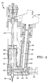
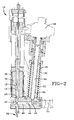
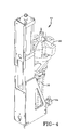
- FIGS 1, 2, and 4 An injection apparatus 10 in accordance with the present invention is illustrated in FIGS 1, 2, and 4.
- the injector 10 has an internal cavity 12 with a plunger 14 to which a charge of molding material is supplied by the extruder 16. Once the internal cavity 12 is filled with material, the plunger 14 is activated to inject the material into an adjacent mold (not shown). To conserve space, the cavity 12 and the extruder 16 are located adjacent to one another, with the extruder 16 inclined at a low angle relative to the cavity 12 to reduce the distance between the exit port 18 of the extruder and the opening of the cavity 20.
- the extruder 16 includes a barrel 22 with a single extruder screw 24 located within the barrel 22.
- An opening (not shown) is provided in the extruder barrel 22 for feeding strips of molding material into the barrel 22.
- the molding material is rubber.
- the extruder screw 24 is driven by a reciprocating motor 26. Since heat is generated within the barrel 22 by mastication of the molding material, coolant flow is provided about the barrel 22 in a coolant flow area 28. The desired temperature is maintained by a thermal jacket 30 and monitored by thermocouplings located about the barrel 22.
- the internal cavity 12 is located within a housing 32. After the cavity 12 is filled with material, the material is pushed out of the cavity 12 by the plunger 14 and to the nozzle 34. The nozzle 34, at that time, is engaged in a sealing relationship with a sprue opening of a mold. To maintain the desired temperature in the internal cavity 12, cooling jacket 36 is provided about the cavity housing 32 and coolant is provided similar to the extruder.
- the check valve 40 Connecting the extruder 16 and the internal cavity 12 and connecting the internal cavity 12 and the nozzle 34 is the check valve 40.
- the check valve 40 has a block configuration, see FIG 3.
- the check valve 40 has an injection outlet port 42 and a transfer column 44.
- the injection outlet port 42 permits material to flow from the internal cavity 12 to the nozzle 34 and the transfer column 44 permits material to flow from the extruder 16 to the cavity 12.
- the injection outlet port 42 is located at one end of the check valve 40.
- the injection outlet port 42 has an internal diameter D V equivalent to the diameter D I of the nozzle tube 46. If desired, for the purpose of altering the material flow pressure, the port diameter D V may be greater than the diameter D I of the nozzle tube 46.
- the injection outlet port 42 connects the nozzle 34 to the internal cavity 12 to allow the molding material to pass from the cavity 12 to the nozzle 34 and into a mold.
- the transfer column 44 connects the extruder 16 and the cavity 12, permitting material to flow from the extruder 16 to the cavity 12 when the injector 10 is being recharged with molding material.
- the column 44 has an entrance port 48 and an exit port 50. When aligned for use, the entrance port 48 connects to the extruder 16 and the exit port 50 connects to the internal cavity 12.
- the illustrated column is shown with two bends 52 in the column. For material flow purposes, any bends 52 in the column 44 are preferably constructed to reduce material build up in the bends 52 and the creation of dead zones.
- a hydraulic cylinder 54 for moving the check valve 40 between the injection and the recharging position.
- the hydraulic cylinder 54 has a position sensor for indicating what position the cylinder 54 is in, and thus, what position the check valve 40 is in.
- the check-valve 40 is in injection position when the injection outlet port 42 is aligned with the nozzle 34 and the internal cavity 12, as seen in FIG. 1.
- the check valve 40 is in recharging position when the transfer column 44 permits the flow of material from the extruder 16 to the cavity 12, as seen in FIG. 2.
- the check valve 40 has a block configuration.
- the configuration may have an overall circular, square, triangular, or polygonal shape.
- the check valve 40 When the check valve 40 is formed in a non-circular block configuration, it reduces any accidental or incidental radial rotation of the check valve 40 within the apparatus, reducing the possibility of misalignment of the injection outlet port 42 and the transfer column 44.
- the main portion of the transfer column 44, and the associated portion of the hydraulic cylinder 54, is illustrated as axially off-center in the check valve 40.
- axially offsetting the column 44 rotation of the check valve 40 is precluded and prevents misalignment of the check valve 40.
- the configuration of the check valve 40 is non-circular, than the transfer column 44 may also be located along the central axis of the block and rotation of the check valve 40 is precluded by the check valve configuration.
- Other means of preventing radial rotation of the check valve 40 may be used in addition to or instead of these specific means.
- Operation of the apparatus occurs in the following manner.
- the hydraulic cylinder 54 is activated to move the transfer column 44 to the recharging position, as seen in FIG. 2. Molding material has been feed into the extruder screw 24. The material is masticated and conditioned by the screw 24. The material flows from the screw 24 into the column 44 and then into the internal cavity 12. As the material flows into the cavity 12, the plunger 14 is pushed back by the material to a position so that the volume in the cavity 12 is approximately equivalent to the volume of rubber to be injected into the mold.
- the hydraulic cylinder 54 is activated to move the check valve 40 into the injecting position, as seen in FIG 1.
- the plunger 14 is then moved forward to shoot the material into the injection outlet port 42 and then into the nozzle 34.
- the nozzle 34 is in contact with the mold sprue port, and the material passes from the nozzle 34 into the mold.
- the hydraulic cylinder 54 is activated to return the check valve 40 to the recharging position, closing off any means for further material to continue to flow into the mold. Material that has already been prepared by the screw 24 now flows, via the transfer column 44, to the internal cavity 12, recharging the injector 10 and preparing for the next molding operation.
- check valve 40 By forming the check valve 40 with two different mechanisms 42, 44 for injecting the material into the mold and for recharging the cavity 12, while the injector 10 is recharging, material cannot flow out of the nozzle 34, and during molding, excess material cannot flow from the screw 24 and into the nozzle 34. Because material cannot flow out the injector 10 during recharging, it makes it possible to recharge the injector 10 while "on the fly;” that is, the injector 10 may be recharged as either the injector 10 is moved to the next mold or as a new mold is being positioned adjacent to the injector 10 for filling.
- the disclosed check valve provides the injector 10 with a consistency and reliability that is not present with conventional check valves and shut-off valves.
Landscapes
- Engineering & Computer Science (AREA)
- Manufacturing & Machinery (AREA)
- Mechanical Engineering (AREA)
- Injection Moulding Of Plastics Or The Like (AREA)
Abstract
Description
- The present invention is directed to an apparatus for injection molding. More specifically, the disclosed apparatus allows for reduced injection cycle time when injecting rubber.
- Injection molding presses for injecting molding materials into molds are well known in the manufacturing industry. Molding materials such as rubber composites must typically be cured within their molds under specific temperature and pressure conditions. Prior to the injection of molding material into the mold, the injection press clamps the mold so that the mold is under pressure during the injection operation.
- The time required for each molding cycle may be six minutes or more. A molding cycle typically includes the steps of clamping the mold, injecting material into the mold, holding the mold in a clamped condition with the injection nozzle still contacting the mold to initiate curing, and recharging the injection unit with material. Such molding cycle times are required, since the molds must remain under pressure within the press to complete the injection operation, initiate curing, and recharge the injection unit with molding material for the next cycle. Recharging of the unit with material occurs during this time in order to prevent any loss of material from the unit and so that when the next mold is presented to the unit for filling, filling may immediately begin.
- US-A- 5,286,186 discloses an apparatus for injection molding rubber.
The apparatus has both a check valve to prevent molding material from passing back into the extruder during injection of the material and a separate shut-off valve to prevent molding material from passing to the injection nozzle during recharging of the internal cavity. The check valve and the shut-off valve do not operate together such that when one is activated the other is automatically operated and material may still pass through one of the valves when not desired. - The present invention provides a new and improved apparatus for performing a molding process. The apparatus is designed to increase the number of molds processed in a specific time period by permitting recharging of the injection molding machine on the fly.
- The injection molding machine has an extruder for providing molding material, a cavity for retaining the molding material prior to injection into a mold, a plunger within the cavity to move the material out of the cavity, and a check valve. The check valve has separate means to permit the material to flow from the extruder to the cavity and from the cavity to an adjacent mold.
- The check valve has an injection outlet port to permit flow from the cavity to an injection nozzle and a transfer column to permit flow from the extruder to the cavity. The injection outlet port and the transfer column are spaced from one another.
- Movement of the check valve from a recharging position to an injecting position is activated by a hydraulic cylinder. The check valve is moved axially along its centerline to move the valve from an injecting position to a recharging position.
- The invention will be described by way of example and with reference to the accompanying drawings in which:
- FIG. 1 is a cross sectional view of the injection apparatus;
- FIG. 2 is a cross sectional view of the injection apparatus;
- FIG. 3 is a cross sectional view of the check valve; and
- FIG. 4 is a perspective view of the injection apparatus.
-
- An
injection apparatus 10 in accordance with the present invention is illustrated in FIGS 1, 2, and 4. Theinjector 10 has aninternal cavity 12 with aplunger 14 to which a charge of molding material is supplied by theextruder 16. Once theinternal cavity 12 is filled with material, theplunger 14 is activated to inject the material into an adjacent mold (not shown). To conserve space, thecavity 12 and theextruder 16 are located adjacent to one another, with theextruder 16 inclined at a low angle relative to thecavity 12 to reduce the distance between theexit port 18 of the extruder and the opening of thecavity 20. - The
extruder 16 includes abarrel 22 with asingle extruder screw 24 located within thebarrel 22. An opening (not shown) is provided in theextruder barrel 22 for feeding strips of molding material into thebarrel 22. Preferably, the molding material is rubber. Theextruder screw 24 is driven by a reciprocatingmotor 26. Since heat is generated within thebarrel 22 by mastication of the molding material, coolant flow is provided about thebarrel 22 in acoolant flow area 28. The desired temperature is maintained by athermal jacket 30 and monitored by thermocouplings located about thebarrel 22. - The
internal cavity 12 is located within ahousing 32. After thecavity 12 is filled with material, the material is pushed out of thecavity 12 by theplunger 14 and to thenozzle 34. Thenozzle 34, at that time, is engaged in a sealing relationship with a sprue opening of a mold. To maintain the desired temperature in theinternal cavity 12,cooling jacket 36 is provided about thecavity housing 32 and coolant is provided similar to the extruder. - Connecting the
extruder 16 and theinternal cavity 12 and connecting theinternal cavity 12 and thenozzle 34 is thecheck valve 40. Thecheck valve 40 has a block configuration, see FIG 3. Thecheck valve 40 has aninjection outlet port 42 and atransfer column 44. Theinjection outlet port 42 permits material to flow from theinternal cavity 12 to thenozzle 34 and thetransfer column 44 permits material to flow from theextruder 16 to thecavity 12. - The
injection outlet port 42 is located at one end of thecheck valve 40. Theinjection outlet port 42 has an internal diameter DV equivalent to the diameter DI of thenozzle tube 46. If desired, for the purpose of altering the material flow pressure, the port diameter DV may be greater than the diameter DI of thenozzle tube 46. When aligned for use, theinjection outlet port 42 connects thenozzle 34 to theinternal cavity 12 to allow the molding material to pass from thecavity 12 to thenozzle 34 and into a mold. - Distanced from the
injection outlet port 42 is thetransfer column 44. Thetransfer column 44 connects theextruder 16 and thecavity 12, permitting material to flow from theextruder 16 to thecavity 12 when theinjector 10 is being recharged with molding material. Thecolumn 44 has anentrance port 48 and anexit port 50. When aligned for use, theentrance port 48 connects to theextruder 16 and theexit port 50 connects to theinternal cavity 12. The illustrated column is shown with twobends 52 in the column. For material flow purposes, anybends 52 in thecolumn 44 are preferably constructed to reduce material build up in thebends 52 and the creation of dead zones. - Below the
check valve 40 is ahydraulic cylinder 54 for moving thecheck valve 40 between the injection and the recharging position. Thehydraulic cylinder 54 has a position sensor for indicating what position thecylinder 54 is in, and thus, what position thecheck valve 40 is in. The check-valve 40 is in injection position when theinjection outlet port 42 is aligned with thenozzle 34 and theinternal cavity 12, as seen in FIG. 1. Thecheck valve 40 is in recharging position when thetransfer column 44 permits the flow of material from theextruder 16 to thecavity 12, as seen in FIG. 2. - As noted, the
check valve 40 has a block configuration. The configuration may have an overall circular, square, triangular, or polygonal shape. When thecheck valve 40 is formed in a non-circular block configuration, it reduces any accidental or incidental radial rotation of thecheck valve 40 within the apparatus, reducing the possibility of misalignment of theinjection outlet port 42 and thetransfer column 44. - The main portion of the
transfer column 44, and the associated portion of thehydraulic cylinder 54, is illustrated as axially off-center in thecheck valve 40. By axially offsetting thecolumn 44, rotation of thecheck valve 40 is precluded and prevents misalignment of thecheck valve 40. If the configuration of thecheck valve 40 is non-circular, than thetransfer column 44 may also be located along the central axis of the block and rotation of thecheck valve 40 is precluded by the check valve configuration. Other means of preventing radial rotation of thecheck valve 40 may be used in addition to or instead of these specific means. - Operation of the apparatus occurs in the following manner. The
hydraulic cylinder 54 is activated to move thetransfer column 44 to the recharging position, as seen in FIG. 2. Molding material has been feed into theextruder screw 24. The material is masticated and conditioned by thescrew 24. The material flows from thescrew 24 into thecolumn 44 and then into theinternal cavity 12. As the material flows into thecavity 12, theplunger 14 is pushed back by the material to a position so that the volume in thecavity 12 is approximately equivalent to the volume of rubber to be injected into the mold. - After the required volume of material is in the
internal cavity 12, thehydraulic cylinder 54 is activated to move thecheck valve 40 into the injecting position, as seen in FIG 1. Theplunger 14 is then moved forward to shoot the material into theinjection outlet port 42 and then into thenozzle 34. At this time, thenozzle 34 is in contact with the mold sprue port, and the material passes from thenozzle 34 into the mold. - After all of the material is transferred to the mold, the
hydraulic cylinder 54 is activated to return thecheck valve 40 to the recharging position, closing off any means for further material to continue to flow into the mold. Material that has already been prepared by thescrew 24 now flows, via thetransfer column 44, to theinternal cavity 12, recharging theinjector 10 and preparing for the next molding operation. - By forming the
check valve 40 with twodifferent mechanisms cavity 12, while theinjector 10 is recharging, material cannot flow out of thenozzle 34, and during molding, excess material cannot flow from thescrew 24 and into thenozzle 34. Because material cannot flow out theinjector 10 during recharging, it makes it possible to recharge theinjector 10 while "on the fly;" that is, theinjector 10 may be recharged as either theinjector 10 is moved to the next mold or as a new mold is being positioned adjacent to theinjector 10 for filling. The disclosed check valve provides theinjector 10 with a consistency and reliability that is not present with conventional check valves and shut-off valves.
Claims (5)
- An apparatus for injection molding material into a mold, the apparatus comprising an extruder (16) for providing molding material, a cavity (12) for retaining the molding material prior to injection into a mold, a plunger (14) within the cavity to move the material out of the cavity, a check valve (40), the check valve being characterized by comprising separate means to permit the material to flow from the extruder (16) to the cavity (12) and from the cavity to an adjacent mold.
- The apparatus in accordance with claim 1 wherein the check valve (40) is activated by a hydraulic cylinder (54).
- The apparatus in accordance with claim 1 wherein the check valve (40) is block shaped.
- The apparatus in accordance with claim 1 wherein the check valve (40) moves axially along its centerline to move the valve from an injecting position to a recharging position.
- The apparatus in accordance with claim 1 wherein the check valve has a radial cross-section configuration selected from the following group of circular, oval, triangular, and polygonal.
Applications Claiming Priority (2)
| Application Number | Priority Date | Filing Date | Title |
|---|---|---|---|
| US09/920,088 US6604936B2 (en) | 2001-08-01 | 2001-08-01 | Apparatus for injection molding |
| US920088 | 2001-08-01 |
Publications (1)
| Publication Number | Publication Date |
|---|---|
| EP1281502A1 true EP1281502A1 (en) | 2003-02-05 |
Family
ID=25443132
Family Applications (1)
| Application Number | Title | Priority Date | Filing Date |
|---|---|---|---|
| EP02016856A Withdrawn EP1281502A1 (en) | 2001-08-01 | 2002-07-30 | Apparatus for injection molding |
Country Status (6)
| Country | Link |
|---|---|
| US (1) | US6604936B2 (en) |
| EP (1) | EP1281502A1 (en) |
| JP (1) | JP2003053809A (en) |
| BR (2) | BR0202849A (en) |
| CA (1) | CA2392516A1 (en) |
| MX (1) | MXPA02006979A (en) |
Families Citing this family (4)
| Publication number | Priority date | Publication date | Assignee | Title |
|---|---|---|---|---|
| WO2004082916A2 (en) * | 2003-03-17 | 2004-09-30 | Manufacturing Technologies International Corporation | Rotary injection molding apparatus and method for use |
| US7393479B2 (en) * | 2004-10-15 | 2008-07-01 | Husky Injection Molding Systems Ltd. | Injection molding three-way shut off valve |
| JP5309845B2 (en) * | 2008-09-30 | 2013-10-09 | 株式会社村田製作所 | Pre-plastic injection molding machine |
| US8328546B2 (en) | 2010-06-29 | 2012-12-11 | Mold-Masters (2007) Limited | Auxiliary injection unit integrated in injection molding system |
Citations (3)
| Publication number | Priority date | Publication date | Assignee | Title |
|---|---|---|---|---|
| FR1438470A (en) * | 1965-03-25 | 1966-05-13 | Transformat Mat Plastiques | Improvements to machines for plastic injection |
| DE4237217A1 (en) * | 1992-11-04 | 1994-05-05 | Spiess Kunststoff Recycling | Payout for filling closed casting moulds with plasticised melt - feeds melt from e.g. extruder through two-way valve to fill pressure chamber and then reverses valve so that shot is expressed into mould(s). |
| US5605707A (en) * | 1993-10-18 | 1997-02-25 | Thermold Partners L.P. | Molding apparatus and a method of using the same |
Family Cites Families (28)
| Publication number | Priority date | Publication date | Assignee | Title |
|---|---|---|---|---|
| US3034175A (en) | 1959-08-22 | 1962-05-15 | Arburg Feingeratefabrik O H G | Injection molding apparatus |
| US3068520A (en) | 1960-01-29 | 1962-12-18 | Arburg Feingeraetefabrik Ohg | Injection molding machine |
| US3173176A (en) | 1961-09-18 | 1965-03-16 | Kobayashi Shoji | Rotary injection moulding machine |
| CH404187A (en) | 1963-09-03 | 1965-12-15 | Netstal Ag Maschf Giesserei | Machine for injecting molded plastic parts |
| FR1560433A (en) | 1968-01-12 | 1969-03-21 | ||
| US4083396A (en) | 1977-04-05 | 1978-04-11 | Ashland Oil, Inc. | Rotary type core-making machine |
| US4547140A (en) | 1983-04-04 | 1985-10-15 | Illinois Precision Corporation | Rotary injection molding press |
| DE3320520C1 (en) | 1983-06-07 | 1984-12-13 | Klöckner-Werke AG, 4100 Duisburg | Hydraulic control for extruder injection units for processing rubber |
| US4695238A (en) | 1985-01-21 | 1987-09-22 | Toyo Machinary & Metal Co., Ltd. | Injection molder |
| US4613475A (en) | 1985-02-19 | 1986-09-23 | Siebolt Hettinga | Clamping structure and method for clamping the mold unit of a mold injection apparatus |
| US5131226A (en) | 1987-07-09 | 1992-07-21 | Milad Limited Partnership | Variable volume reservoir and method for its use |
| JPH0661801B2 (en) | 1988-07-13 | 1994-08-17 | 住友重機械工業株式会社 | Motor control device for electric injection molding machine |
| US4976603A (en) | 1989-05-17 | 1990-12-11 | Husky Injection Molding Systems, Ltd. | Pivoting workpiece removal device |
| US5286186A (en) | 1990-11-30 | 1994-02-15 | Gencorp Inc. | Apparatus for injection into a self-clamping mold |
| US5122051A (en) | 1991-01-10 | 1992-06-16 | Cincinnati Milacron Inc. | Molded part ejection apparatus |
| JPH082586B2 (en) | 1991-01-31 | 1996-01-17 | 日精エー・エス・ビー機械株式会社 | Rotary molding machine |
| US5112213A (en) | 1991-02-26 | 1992-05-12 | Van Dorn Company | Driven ring-type non-return valve for injection molding |
| AT400235B (en) | 1991-04-26 | 1995-11-27 | Engel Gmbh Maschbau | HANDLING DEVICE FOR REMOVING MOLDED PLASTIC SPLASHERS |
| US5112212A (en) | 1991-05-02 | 1992-05-12 | Husky Injection Molding Systems Ltd. | Shooting pot with combined valve and piston |
| US5153007A (en) | 1991-05-29 | 1992-10-06 | Illinois Precision Corporation | Rotary injection molding press |
| DE4122617A1 (en) | 1991-07-09 | 1993-02-18 | Waldorf Veronika | DEVICE FOR INSERTING AND / OR REMOVING ITEMS IN / OR FROM A MACHINE |
| US5435715A (en) | 1992-10-26 | 1995-07-25 | Campbell; Gerald D. | Multi-station injection molding apparatus |
| DE19517009A1 (en) * | 1995-05-10 | 1996-11-14 | Kautex Maschinenbau Gmbh | Injection molding machine for processing thermoplastics |
| AU7829898A (en) | 1997-06-11 | 1998-12-30 | Vertech Systems, Llc | Injection molding machine and method with integrated carriage assembly |
| WO1998057787A2 (en) | 1997-06-19 | 1998-12-23 | Plastic Pallet Production, Inc. | Multiple mold workstation with single injection feeder and hydraulic pumping station |
| US6086353A (en) | 1998-02-17 | 2000-07-11 | Cincinnati Milacron Inc. | Two-stage electric injection unit with rotating plunger |
| US5975872A (en) | 1998-02-23 | 1999-11-02 | Illinois Precision Corp. | Direct drive injection molding apparatus |
| US6203311B1 (en) | 1998-05-04 | 2001-03-20 | Robert F. Dray | Sliding ring non-return valve |
-
2001
- 2001-08-01 US US09/920,088 patent/US6604936B2/en not_active Expired - Fee Related
-
2002
- 2002-07-05 CA CA002392516A patent/CA2392516A1/en not_active Abandoned
- 2002-07-17 MX MXPA02006979A patent/MXPA02006979A/en active IP Right Grant
- 2002-07-24 BR BR0202849-2A patent/BR0202849A/en not_active Application Discontinuation
- 2002-07-24 BR BR0202848-4A patent/BR0202848A/en not_active Application Discontinuation
- 2002-07-30 EP EP02016856A patent/EP1281502A1/en not_active Withdrawn
- 2002-08-01 JP JP2002224606A patent/JP2003053809A/en active Pending
Patent Citations (3)
| Publication number | Priority date | Publication date | Assignee | Title |
|---|---|---|---|---|
| FR1438470A (en) * | 1965-03-25 | 1966-05-13 | Transformat Mat Plastiques | Improvements to machines for plastic injection |
| DE4237217A1 (en) * | 1992-11-04 | 1994-05-05 | Spiess Kunststoff Recycling | Payout for filling closed casting moulds with plasticised melt - feeds melt from e.g. extruder through two-way valve to fill pressure chamber and then reverses valve so that shot is expressed into mould(s). |
| US5605707A (en) * | 1993-10-18 | 1997-02-25 | Thermold Partners L.P. | Molding apparatus and a method of using the same |
Also Published As
| Publication number | Publication date |
|---|---|
| JP2003053809A (en) | 2003-02-26 |
| BR0202848A (en) | 2003-05-20 |
| CA2392516A1 (en) | 2003-02-01 |
| MXPA02006979A (en) | 2003-02-24 |
| US6604936B2 (en) | 2003-08-12 |
| US20030026870A1 (en) | 2003-02-06 |
| BR0202849A (en) | 2003-05-20 |
Similar Documents
| Publication | Publication Date | Title |
|---|---|---|
| CN1086627C (en) | Preplasticizing injection moulding apparatus | |
| EP0443387A1 (en) | Injection molding system having spring biased nozzles | |
| US5454995A (en) | Method for reducing cycle time in an injection molding machine | |
| EP0163083A2 (en) | Injection molding peripheral opening core ring gate | |
| JPH1199544A (en) | Improved shooting pot | |
| DE69919809T2 (en) | micro injection | |
| CN101579911B (en) | Injection molding machine apparatus and method with moving platen injection and ejection actuation | |
| JP2548956B2 (en) | Hydraulic system for toggle plastic injection molding machine with precision coining | |
| MXPA06014089A (en) | Apparatus and method for actuation of injection molding shooting pots. | |
| CN1064235A (en) | Improved Hot Runner Mold Device and Its Application | |
| US5182118A (en) | Plasticizing apparatus for use in an injection molding machine | |
| US6604936B2 (en) | Apparatus for injection molding | |
| US20030107154A1 (en) | Production of moulded articles and apparatus for producing moulded articles | |
| JPH11114990A (en) | Pre-plasticization type injection device and injection molding method using the same | |
| CA2048106A1 (en) | Injection molding machine with pressure assist nozzle | |
| EP0402503B1 (en) | Injection molding system having valve member split ring | |
| CN1976792B (en) | Apparatus for sealing injection unit and sprue | |
| WO1998056563A1 (en) | Injection molding machine and method with integrated carriage assembly | |
| EP1333968B1 (en) | Injection unit of an injection system | |
| CN1091024C (en) | Injection molding device | |
| GB2254283A (en) | Improvements in plasticising units for screw injection moulding machines | |
| JP3459214B2 (en) | Pre-plasticizing injection equipment | |
| US7125242B2 (en) | Decompression device for an injection molding apparatus | |
| WO2002060671A1 (en) | Injection nozzle | |
| JPH0612026U (en) | Injection device |
Legal Events
| Date | Code | Title | Description |
|---|---|---|---|
| PUAI | Public reference made under article 153(3) epc to a published international application that has entered the european phase |
Free format text: ORIGINAL CODE: 0009012 |
|
| AK | Designated contracting states |
Designated state(s): AT BE BG CH CY CZ DE DK EE ES FI FR GB GR IE IT LI LU MC NL PT SE SK TR |
|
| AX | Request for extension of the european patent |
Extension state: AL LT LV MK RO SI |
|
| 17P | Request for examination filed |
Effective date: 20030805 |
|
| 17Q | First examination report despatched |
Effective date: 20030829 |
|
| AKX | Designation fees paid |
Designated state(s): DE FR GB IT |
|
| 17Q | First examination report despatched |
Effective date: 20030829 |
|
| GRAP | Despatch of communication of intention to grant a patent |
Free format text: ORIGINAL CODE: EPIDOSNIGR1 |
|
| STAA | Information on the status of an ep patent application or granted ep patent |
Free format text: STATUS: THE APPLICATION IS DEEMED TO BE WITHDRAWN |
|
| 18D | Application deemed to be withdrawn |
Effective date: 20080704 |