EP1281371B1 - Dental instrument - Google Patents
Dental instrument Download PDFInfo
- Publication number
- EP1281371B1 EP1281371B1 EP02255269A EP02255269A EP1281371B1 EP 1281371 B1 EP1281371 B1 EP 1281371B1 EP 02255269 A EP02255269 A EP 02255269A EP 02255269 A EP02255269 A EP 02255269A EP 1281371 B1 EP1281371 B1 EP 1281371B1
- Authority
- EP
- European Patent Office
- Prior art keywords
- instrument
- stem
- cone
- handle
- glue
- Prior art date
- Legal status (The legal status is an assumption and is not a legal conclusion. Google has not performed a legal analysis and makes no representation as to the accuracy of the status listed.)
- Expired - Lifetime
Links
- 229910052751 metal Inorganic materials 0.000 claims abstract description 15
- 239000002184 metal Substances 0.000 claims abstract description 15
- 239000003292 glue Substances 0.000 claims description 11
- 230000001747 exhibiting effect Effects 0.000 claims 1
- 229920005989 resin Polymers 0.000 abstract description 26
- 239000011347 resin Substances 0.000 abstract description 26
- 239000000853 adhesive Substances 0.000 abstract description 14
- 230000001070 adhesive effect Effects 0.000 abstract description 14
- 238000012360 testing method Methods 0.000 abstract description 5
- 239000007787 solid Substances 0.000 abstract description 3
- 230000002093 peripheral effect Effects 0.000 description 10
- 230000009977 dual effect Effects 0.000 description 5
- 238000000034 method Methods 0.000 description 5
- 230000008569 process Effects 0.000 description 3
- 230000001954 sterilising effect Effects 0.000 description 3
- 238000004659 sterilization and disinfection Methods 0.000 description 3
- 229910001369 Brass Inorganic materials 0.000 description 2
- 229910052782 aluminium Inorganic materials 0.000 description 2
- XAGFODPZIPBFFR-UHFFFAOYSA-N aluminium Chemical compound [Al] XAGFODPZIPBFFR-UHFFFAOYSA-N 0.000 description 2
- 239000010951 brass Substances 0.000 description 2
- 238000005219 brazing Methods 0.000 description 2
- 238000013461 design Methods 0.000 description 2
- 229920006335 epoxy glue Polymers 0.000 description 2
- 238000012986 modification Methods 0.000 description 2
- 230000004048 modification Effects 0.000 description 2
- 230000003014 reinforcing effect Effects 0.000 description 2
- 230000004044 response Effects 0.000 description 2
- 229910001220 stainless steel Inorganic materials 0.000 description 2
- 239000010935 stainless steel Substances 0.000 description 2
- 239000004593 Epoxy Substances 0.000 description 1
- 244000273618 Sphenoclea zeylanica Species 0.000 description 1
- 238000004026 adhesive bonding Methods 0.000 description 1
- 230000004888 barrier function Effects 0.000 description 1
- 239000011324 bead Substances 0.000 description 1
- 239000000919 ceramic Substances 0.000 description 1
- 238000005520 cutting process Methods 0.000 description 1
- 230000001627 detrimental effect Effects 0.000 description 1
- 229920001971 elastomer Polymers 0.000 description 1
- 239000000806 elastomer Substances 0.000 description 1
- 238000004519 manufacturing process Methods 0.000 description 1
- 239000000463 material Substances 0.000 description 1
- 230000007246 mechanism Effects 0.000 description 1
- 230000002028 premature Effects 0.000 description 1
- 238000012545 processing Methods 0.000 description 1
- 229910052710 silicon Inorganic materials 0.000 description 1
- 239000010703 silicon Substances 0.000 description 1
Images



Classifications
-
- A—HUMAN NECESSITIES
- A61—MEDICAL OR VETERINARY SCIENCE; HYGIENE
- A61C—DENTISTRY; APPARATUS OR METHODS FOR ORAL OR DENTAL HYGIENE
- A61C3/00—Dental tools or instruments
Definitions
- the present invention pertains to dental instruments. More particularly, the present invention pertains to such instruments with handles that are of large diameter and more comfortable to use.
- a number of dental instruments such as scalers, have been marketed with elongated plastic handles as an alternative to traditional metal handles.
- Light weight, relatively large diameter resin handles are preferred by some dental professionals as they tend to reduce hand fatigue.
- Resin handles with large diameters are not only comfortable to use, their weight does not increase significantly (despite their diameter values being large), this being attributed to the lower density of resin when compared to other materials that have been previously used for the same purpose, such as stainless steel, aluminum or brass.
- Resin handles have advantages in that they usually exhibit lower manufacturing cost than is the case with stainless steel, aluminum, brass or ceramic handles. In addition, resin permits greater design latitude than is the case with metal.
- a greater degree of torque resistance can be attained by using a tubular metal insert around which the resin handle is molded.
- the tip can then be press-fitted into the metal insert.
- the thin wall of the insert may deform outwardly to some extent in this process creating undesirable circumferential hoop stress in the ends of the resin handle. This hoop stress can shorten the life of the instrument and should be avoided.
- a dental instrument comprising: an elongated metal tube, hollow at least at one end; and at least one cone having a stem and an instrument-receiving portion; characterised by an overmolded plastic handle locked axially and rotatably to the metal tube, the tube having an exterior periphery and first and second spirals formed in the periphery; and characterised in that the stem includes at least one laterally-oriented, glue-receiving opening, the glue-receiving opening being displaced from and not engaging the tube, whereby when the stem is inserted into a glue-filled hollow end of the tube, the glue interacts with the opening and, when cured, locks the cone to the tube to prevent at least rotation of the cone relative to the tube.
- a dental instrument comprising an elongated metal tube, hollow at least at one end, forming a handle and a cone having a stem and an instrument-receiving portion.
- the connection between the handle and the cone is formed by brazing, not gluing. Brazing cannot be used where plastic handles are used, as in the present invention.
- DE 3722368A discloses a dental instrument in which a mechanical connection is provided between the instrument and the hand piece, the connection being provided by mutually engageable protrusions and recesses which mate when the instrument is pulled into the recess of the handpiece. All of the stems of the instrument have a continuous, unperforated periphery.
- the present invention relates to a dental instrument as claimed in claim 1.
- the plastic handle of the present invention could have an exemplary diameter on the order of 0.9906 cm (0.390 inches).
- the tube could have an exemplary diameter on the order of 5.5563 cm (0.219 inches).
- the solid adhesive barrier in combination with the cone and metal tube resists applied torque in excess of 3.39 Nm (30 inch-pounds) with a relatively light-weight metal tube. This result can be achieved with reduced interference, by way of a weaker fit, between the hollow end of the tube and the stem of the cone, and without subjecting the plastic handle to undesirable hoop stress.
- the additional torsional strength is achieved without increasing the force needed to press-fit the cone into the insert.
- Hoop stress which is particularly detrimental in resin handles, can increase exponentially with an increase in press-fit forces.
- the slot, or hole, at the free end of the cone helps to achieve the desired torsional strength, on the order of 400 newton-centimeters, without increasing the press-fit (the hoop stress causing mechanism), thereby maintaining the structural integrity of the instrument.
- a bead of epoxy glue may be used to hold the cone securely in place once the glue has been cured.
- the epoxy glue is repeatedly sterilizable.
- Fig. 1 illustrates an instrument 10 according to one embodiment of the present invention.
- the instrument 10 includes a reinforcing hollow core, or insert 12, which has formed thereon, by cutting or any other form of processing, dual reverse spirals 12a and 12b.
- An elongated resin handle, generally indicated at 14, is molded around the reinforcing insert 12.
- the resin 14a flows into the dual spirals 12a, 12b and when cured is locked to the insert 12, thereby precluding axial and/or rotary movement between insert 12 and handle 14.
- Figs. 1C and 1D illustrate an insert 12' which has dual reverse spirals 12a', b'.
- the various exemplary cross-sections of spirals 12a', b' from region 12'-i are illustrated in Figs. 1E-1H. Other cross-sections are possible and come within the scope of the claims.
- Rings 12'-5a, b can be formed in insert 12' and provide additional features which resin 14a can engage with, and lock onto, when cured.
- Fig. 1A illustrates a sectional view of insert 12 bonded to handle 14.
- the design of the handle includes an overhang 14a, illustrated at each end of handle 14 relative to insert 12.
- the presence of the overhang 14a at each end of the handle 14 compensates for a potentially higher degree of axial expansion of the insert 12, compared to resin handle 14, during sterilization so that end 12c of insert 12 never extends beyond end 14b of resin handle 14. It will be understood that a single-ended instrument will exhibit the same configuration at the end where the instrument, or mirror, is attached.
- resin handle 14 can be molded of any suitable medical grade plastic, or elastomers including silicon, without departing from the scope of the claims. Further, while preferably the overhang 14a is on the order of 0.381mm (fifteen thousandths of an inch), between the end 12c of the insert 12 and the end 14b of the resin handle, it will be understood that other amounts of overhang come within the spirit and scope of the present invention.
- Instrument 10 is illustrated for purposes of the present disclosure as a double-ended instrument having treatment applying tips 18a, 18b.
- the shape of the tips 18a, 18b can vary, depending on the desired type of instrument, without departing from the spirit and scope of the present invention. It will also be understood that single-ended instruments having only a single operative tip, such as tip 18a, or perhaps a mirror, come within the scope of the claims.
- Each of the tips 18a, 18b is coupled to a respective end of handle 14 by means of a respective cone 20a, 20b.
- Each of the cones 20a, 20b is substantially identical so a discussion of cone 20a will also describe cone 20b.
- cone 20a has a first, or instrument, receiving end generally indicated at 22 and a second, or stem end 24.
- Instrument- receiving end 22 is hollow with an interior peripheral surface 22a which terminates at an exterior end 22b.
- a proximal end 18a-1 of the tip 18a is press-fitted into the instrument receiving end 22.
- a cylindrical surface 22c slidably receives an elastomeric colour-coded overlay, such as overlays 20a-1, 20b-1.
- overlays 20a-1, 20b-1 provide additional non-slip surfaces for a practitioner's fingers while using the instrument 10.
- the stem 24 is formed with a cylindrical interior peripheral surface 24a which extends axially along a central axis "A" of the cone 22. Stem 24 also exhibits, on an exterior peripheral surface thereof, first and second oppositely tapered, abutting, surfaces 24d, e which intersect and form, as discussed in more detail below, an adhesive, or glue, trap, with an interior peripheral surface 12d of the insert 12.
- Tapered surface 24e terminates at a cylindrical exterior peripheral region 24f of stem 24, which in turn abuts an enlarged annular region 26.
- the region 26 is interposed between the insert receiving region 22 and the stem 24.
- an annular surface 26a abuts end 14b of resin handle 14.
- a pair of slots 30a, 30b are formed in the stem 24 adjacent to end 24b.
- the slots 30a, 30b can be formed in a variety of shapes without departing from the scope of the claims.
- the slots 30a, 30b provide a torque lock which couples insert 12 to cone 20a, thereby precluding rotation therebetween in response to applied torques of at least 400 newton-centimeters in accordance with ISO 13397-1.
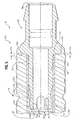
- Fig. 5 illustrates in more detail the relationship between insert 12, handle 14 and representative cone 20a when assembled together.
- stem 24 is slidably received into a hollow end of insert 12, perhaps with a press-fit, in the vicinity of peripheral surface 24f, if desired.
- the end of the insert 12 Prior to inserting cone 20a, the end of the insert 12 is filled with a glue or adhesive 32, such as an epoxy.
- a glue or adhesive 32 such as an epoxy.
- the adhesive 32 fills the glue trap formed of abutting, reverse tapered surfaces 24d, 24e as well as the slot, or slots 30a, 30b.
- the glue 32 also flows into the hollow interior of stem 24 bounded by surface 24a.
- a solid mass fills the annular glue trap formed by reverse tapered surfaces 24d, 24e and interior cylindrical surface 12d. This mass extends between slots 30a, b into hollow stem 24, generally in contact with interior peripheral surface 12d.
- the cured adhesive 32 is effective not only to block axial movement of cone 20a during use but also blocks rotary movement of cone 20a relative to stem 12 in response to any applied torque during use.
- the locking structure of the cured adhesive in the slots 30a, 30b, as well as being in contact with the internal peripheral surface 12d of insert 12, are highly effective in resisting rotation of the cone 20a due to applied torque.
- the operative tips such as tip 18a
- the respective cone such as cone 20a
- the cones 20a, 20b is/are glued into the respective insert 12 and handle 14.
- Fig. 5 also illustrates overhang 14a between end 12c of insert 12 and end 14b of handle 4.
- Surface 26a abuts the end 14b of the handle 14.
- cone 20a has been preferably described as having slots 30a, 30b, it will be understood that other numbers and shapes of slots such as 1, 3, or more come within the scope of the claims.
- Figs. 6-8 illustrate another form of a cone 20c in an embodiment of the present invention. Those portions of cone 20c which correspond to the structure of cones 20a, 20b have been assigned the same identification numerals.
- cone 20c exhibits one or more holes or openings 32a in corresponding stem 24'. It will be understood that as stem 24' is slid into a respective end, such as end 12-1 of insert 12, the adhesive therein flows into opening or openings 32a, 32b as well as into a hollow interior of stem 24' bounded by surface 24a'. This creates a mass of adhesive both within and around stem 24', which, when cured and in combination with interior surface 12d of insert 12, resists rotary motion between cone 24' and respective insert 12 and handle 14.
- stem 24' also exhibits first and second reverse tapered surfaces 24d', 24e', which, in turn, with an interior peripheral surface 12d of the insert 12, form a glue-trap precluding axial movement of cone 20c relative to the respective insert/handle combination 12, 14.
- openings 32a have been illustrated as circular, other forms of openings come within the scope of the claims.
Landscapes
- Health & Medical Sciences (AREA)
- Oral & Maxillofacial Surgery (AREA)
- Dentistry (AREA)
- Epidemiology (AREA)
- Life Sciences & Earth Sciences (AREA)
- Animal Behavior & Ethology (AREA)
- General Health & Medical Sciences (AREA)
- Public Health (AREA)
- Veterinary Medicine (AREA)
- Dental Tools And Instruments Or Auxiliary Dental Instruments (AREA)
Abstract
Description
- The present invention pertains to dental instruments. More particularly, the present invention pertains to such instruments with handles that are of large diameter and more comfortable to use.
- A number of dental instruments, such as scalers, have been marketed with elongated plastic handles as an alternative to traditional metal handles. Light weight, relatively large diameter resin handles are preferred by some dental professionals as they tend to reduce hand fatigue. Resin handles with large diameters are not only comfortable to use, their weight does not increase significantly (despite their diameter values being large), this being attributed to the lower density of resin when compared to other materials that have been previously used for the same purpose, such as stainless steel, aluminum or brass.
- Resin handles have advantages in that they usually exhibit lower manufacturing cost than is the case with stainless steel, aluminum, brass or ceramic handles. In addition, resin permits greater design latitude than is the case with metal.
- Known resin handled scalers have a diameter on the order of 0.9525 - 1.0414 cm (0.375-0.410 inches). Metal scalers have handles with diameters on the order of 0.6858 -0.9525 cm (0.270-0.375 inches).
- Known resin handle scalers have, however, certain limitations. Many known resin-handled instruments do not appear capable of passing the currently specified torque test of ISO 13397-1 issued in December 15, 1995. That test mandates that an applicable instrument must be able to pass an applied torque test of 400 newton-centimeters (35.4 inch-pounds) without damage or relative motion between the instrument's operating tip and the respective resin handle. Some commercially available scalers with resin handles can tolerate only about 2.03 Nm (18 inch-pounds) of applied torque without damage or relative motion between handle and tip.
- One way to increase the amount of torque which the instrument can resist is to increase the force necessary to press-fit the tip of the instrument into the handle. This technique, which increases the interference between the press-fitted surfaces, is not suitable for use in resin-handled instruments.
- A greater degree of torque resistance can be attained by using a tubular metal insert around which the resin handle is molded. The tip can then be press-fitted into the metal insert. However, the thin wall of the insert may deform outwardly to some extent in this process creating undesirable circumferential hoop stress in the ends of the resin handle. This hoop stress can shorten the life of the instrument and should be avoided.
- Increasing the thickness of the wall of the insert tends to reduce hoop stress at the expense of adding weight to the instrument. The increased weight detracts from the advantages of using resin, making this a less desirable solution.
- It is desirable to provide dental instruments with light-weight resin handles, which handles can pass the ISO 13397-1 torque test and which are usable over a time period comparable to previously-proposed handles made of metal.
- According to the present invention, there is provided a dental instrument comprising: an elongated metal tube, hollow at least at one end; and at least one cone having a stem and an instrument-receiving portion;
characterised by an overmolded plastic handle locked axially and rotatably to the metal tube, the tube having an exterior periphery and first and second spirals formed in the periphery; and characterised in that the stem includes at least one laterally-oriented, glue-receiving opening, the glue-receiving opening being displaced from and not engaging the tube, whereby when the stem is inserted into a glue-filled hollow end of the tube, the glue interacts with the opening and, when cured, locks the cone to the tube to prevent at least rotation of the cone relative to the tube. - The applicant's US Patent No. 6109918 upon which prior art the two part form of
claim 1 is based, discloses a dental instrument comprising an elongated metal tube, hollow at least at one end, forming a handle and a cone having a stem and an instrument-receiving portion.
The connection between the handle and the cone is formed by brazing, not gluing. Brazing cannot be used where plastic handles are used, as in the present invention. - DE 3722368A discloses a dental instrument in which a mechanical connection is provided between the instrument and the hand piece, the connection being provided by mutually engageable protrusions and recesses which mate when the instrument is pulled into the recess of the handpiece. All of the stems of the instrument have a continuous, unperforated periphery.
- The present invention relates to a dental instrument as claimed in
claim 1. - The plastic handle of the present invention could have an exemplary diameter on the order of 0.9906 cm (0.390 inches). The tube could have an exemplary diameter on the order of 5.5563 cm (0.219 inches).
- The solid adhesive barrier in combination with the cone and metal tube resists applied torque in excess of 3.39 Nm (30 inch-pounds) with a relatively light-weight metal tube. This result can be achieved with reduced interference, by way of a weaker fit, between the hollow end of the tube and the stem of the cone, and without subjecting the plastic handle to undesirable hoop stress.
- The additional torsional strength is achieved without increasing the force needed to press-fit the cone into the insert. Hoop stress, which is particularly detrimental in resin handles, can increase exponentially with an increase in press-fit forces. A build up of such hoop stress at each end, although invisible when the instrument is new, can lead to premature failure of the resin when subjected to repeated sterilization. The slot, or hole, at the free end of the cone, helps to achieve the desired torsional strength, on the order of 400 newton-centimeters, without increasing the press-fit (the hoop stress causing mechanism), thereby maintaining the structural integrity of the instrument.
- A bead of epoxy glue may be used to hold the cone securely in place once the glue has been cured. The epoxy glue is repeatedly sterilizable.
- Reference will now be made, by way of example, to the accompanying drawings, in which:
- Fig.1 is an exploded view of an exemplary instrument in accordance with an embodiment of the present invention;
- Fig. 1A is a sectional view, illustrating details of the handle of Fig. 1, taken
along
plane 1A-1A of Fig. 1; - Fig. 1B is an enlarged sectional view of a portion of an end of the handle of Fig. 1A;
- Fig. 1C is an enlarged side elevational view of another insert usable in the instrument of Fig. 1;
- Fig. 1D is an enlarged sectional view taken along plane 1D-1D of Fig. 1C;
- Figs. 1E-1H are fragmentary enlarged views of a portion of the insert of Fig. 1D;
- Fig. 2 is a perspective view of an instrument provided with a cone of a type usable in the instrument of Fig. 1;
- Fig. 3 is an end view of the cone of Fig. 2;
- Fig. 4 is a side sectional view of the cone of Fig. 3 taken along plane 4-4 of Fig. 3;
- Fig. 5 is an enlarged sectional, fragmentary view of an end of the instrument of Fig. 1 illustrating further details of the relationship between the components thereof;
- Fig. 6 is a perspective view of another cone in an embodiment of the present invention;
- Fig. 7 is an end view of the cone of Fig. 6; and
- Fig. 8 is a side sectional view of the cone of Fig. 7 taken along plane 8-8 thereof.
-
- While this invention is susceptible of embodiment in many different forms, there are shown in the drawing and will be described herein in detail specific embodiments thereof with the understanding that the present disclosure is to be considered as an exemplification of the principles of the invention and is not intended to limit the invention to the specific embodiments illustrated.
- Fig. 1 illustrates an
instrument 10 according to one embodiment of the present invention. Theinstrument 10 includes a reinforcing hollow core, orinsert 12, which has formed thereon, by cutting or any other form of processing, dualreverse spirals - An elongated resin handle, generally indicated at 14, is molded around the reinforcing
insert 12. Theresin 14a flows into thedual spirals insert 12, thereby precluding axial and/or rotary movement betweeninsert 12 and handle 14. - The
dual spirals insert 12, to which thehandle 14 is bonded, overcome potential, thermally-induced, axial forces such that theinsert 12 cannot move axially due to expansion produced from sterilization heat. Additionally, the bonding between theresin handle 14 and thespirals insert 12 locks thehandle 14 and insert 12 together so as to block both axial and rotary movement therebetween when in use. - It will be understood that a variety of instruments can be used to cut or form the dual reverse spirals 12a, 12b in the exterior periphery of the
insert 12. Additionally, the cross-section of thespirals insert 12. - In contrast to insert 12 shown in Fig. 1A, Figs. 1C and 1D illustrate an insert 12' which has dual reverse spirals 12a', b'. The various exemplary cross-sections of
spirals 12a', b' from region 12'-i are illustrated in Figs. 1E-1H. Other cross-sections are possible and come within the scope of the claims. - Rings 12'-5a, b can be formed in insert 12' and provide additional features which
resin 14a can engage with, and lock onto, when cured. - Fig. 1A illustrates a sectional view of
insert 12 bonded to handle 14. As best illustrated in Fig. 1B, the design of the handle includes anoverhang 14a, illustrated at each end ofhandle 14 relative to insert 12. The presence of theoverhang 14a at each end of thehandle 14 compensates for a potentially higher degree of axial expansion of theinsert 12, compared to resin handle 14, during sterilization so thatend 12c ofinsert 12 never extends beyondend 14b ofresin handle 14. It will be understood that a single-ended instrument will exhibit the same configuration at the end where the instrument, or mirror, is attached. - It will be understood that resin handle 14 can be molded of any suitable medical grade plastic, or elastomers including silicon, without departing from the scope of the claims. Further, while preferably the
overhang 14a is on the order of 0.381mm (fifteen thousandths of an inch), between theend 12c of theinsert 12 and theend 14b of the resin handle, it will be understood that other amounts of overhang come within the spirit and scope of the present invention. -
Instrument 10 is illustrated for purposes of the present disclosure as a double-ended instrument havingtreatment applying tips tips tip 18a, or perhaps a mirror, come within the scope of the claims. - Each of the
tips handle 14 by means of arespective cone cones cone 20a will also describecone 20b. - As illustrated in Figs. 2-4,
cone 20a has a first, or instrument, receiving end generally indicated at 22 and a second, or stemend 24. Instrument- receivingend 22, is hollow with an interiorperipheral surface 22a which terminates at an exterior end 22b. During the assembly process, aproximal end 18a-1 of thetip 18a is press-fitted into theinstrument receiving end 22. - A
cylindrical surface 22c slidably receives an elastomeric colour-coded overlay, such asoverlays 20a-1, 20b-1. In addition to colour coding, in order to identify type of instrument, office or procedure, overlays 20a-1, 20b-1 provide additional non-slip surfaces for a practitioner's fingers while using theinstrument 10. - The
stem 24 is formed with a cylindrical interiorperipheral surface 24a which extends axially along a central axis "A" of thecone 22.Stem 24 also exhibits, on an exterior peripheral surface thereof, first and second oppositely tapered, abutting, surfaces 24d, e which intersect and form, as discussed in more detail below, an adhesive, or glue, trap, with an interiorperipheral surface 12d of theinsert 12. -
Tapered surface 24e terminates at a cylindrical exteriorperipheral region 24f ofstem 24, which in turn abuts an enlargedannular region 26. Theregion 26 is interposed between theinsert receiving region 22 and thestem 24. When assembled, anannular surface 26a abutsend 14b ofresin handle 14. - A pair of
slots stem 24 adjacent to end 24b. Theslots - When
instrument 10 has been assembled, as discussed in more detail subsequently, theslots cone 20a, thereby precluding rotation therebetween in response to applied torques of at least 400 newton-centimeters in accordance with ISO 13397-1. - Fig. 5 illustrates in more detail the relationship between
insert 12, handle 14 andrepresentative cone 20a when assembled together. As illustrated in Fig. 5, stem 24 is slidably received into a hollow end ofinsert 12, perhaps with a press-fit, in the vicinity ofperipheral surface 24f, if desired. - Prior to inserting
cone 20a, the end of theinsert 12 is filled with a glue or adhesive 32, such as an epoxy. As thestem 24 slides along the internalperipheral surface 12d ofinsert 12, the adhesive 32 fills the glue trap formed of abutting, reverse taperedsurfaces slots glue 32 also flows into the hollow interior ofstem 24 bounded bysurface 24a. - When the adhesive 32 has cured, a solid mass fills the annular glue trap formed by reverse tapered
surfaces cylindrical surface 12d. This mass extends betweenslots 30a, b intohollow stem 24, generally in contact with interiorperipheral surface 12d. - The cured adhesive 32 is effective not only to block axial movement of
cone 20a during use but also blocks rotary movement ofcone 20a relative to stem 12 in response to any applied torque during use. The locking structure of the cured adhesive in theslots peripheral surface 12d ofinsert 12, are highly effective in resisting rotation of thecone 20a due to applied torque. - It will be understood that the exact details of assembly of the
instrument 10 are not a limitation of the present invention. In this regard, the operative tips, such astip 18a, can be press-fitted into the respective cone, such ascone 20a, either before or after thecones respective insert 12 and handle 14. - Fig. 5 also illustrates
overhang 14a betweenend 12c ofinsert 12 andend 14b ofhandle 4.Surface 26a abuts theend 14b of thehandle 14. - While
cone 20a has been preferably described as havingslots - Figs. 6-8 illustrate another form of a
cone 20c in an embodiment of the present invention. Those portions ofcone 20c which correspond to the structure ofcones - In contrast to
cones cone 20c exhibits one or more holes oropenings 32a in corresponding stem 24'. It will be understood that as stem 24' is slid into a respective end, such as end 12-1 ofinsert 12, the adhesive therein flows into opening oropenings 32a, 32b as well as into a hollow interior of stem 24' bounded bysurface 24a'. This creates a mass of adhesive both within and around stem 24', which, when cured and in combination withinterior surface 12d ofinsert 12, resists rotary motion between cone 24' andrespective insert 12 and handle 14. - As discussed above, stem 24' also exhibits first and second reverse tapered
surfaces 24d', 24e', which, in turn, with an interiorperipheral surface 12d of theinsert 12, form a glue-trap precluding axial movement ofcone 20c relative to the respective insert/handle combination - It will be understood that while
openings 32a have been illustrated as circular, other forms of openings come within the scope of the claims. - From the foregoing, it will be observed that numerous variations and modifications may be effected without departing from the scope of the claims. It is to be understood that no limitation with respect to the specific apparatus illustrated herein is intended or should be inferred. It is, of course, intended to cover by the appended claims all such modifications as fall within the scope of the claims.
Claims (10)
- A dental instrument (10) comprising:characterised by an overmolded plastic handle (14) locked axially and rotatably to the metal tube (12), the tube (12) having an exterior periphery and first and second spirals (12a, 12b) formed in the periphery;an elongated metal tube (12), hollow at least at one end; andat least one cone (20a, 20b; 20c) having a stem (24; 24') and an instrument-receiving portion (22);
and characterised in that the stem (24; 24') includes at least one laterally-oriented, glue-receiving opening (30a, 30b; 32a, 32b), the glue-receiving opening (30a, 30b; 32a, 32b) being displaced from and not engaging the tube (12), whereby when the stem (24; 24') is inserted into a glue-filled hollow end of the tube (12), the glue interacts with the opening (30a, 30b; 32a, 32b) and, when cured, locks the cone (20a, 20b; 20c) to the tube (12) to prevent at least rotation of the cone (20a, 20b; 20c) relative to the tube (12). - An instrument as in claim 1 wherein the glue-receiving opening (30a, 30b; 32a, 32b) comprises one of a slot (30a, 30b) in the stem (24) or a hole (32a, 32b) in the stem (24').
- An instrument as in claim 2 which carries at least one treatment tip (18a, 18b: 46a, 46b), wherein the tip (18a, 18b: 46a, 46b) engages the instrument-receiving portion (22) of the cone (20a, 20b; 20c) with an interference fit.
- An instrument as in claim 1 wherein the glue-receiving opening (30a, 30b; 32a, 32b) comprises at least one axially oriented elongated slot (30a, 30b) formed in the stem (24) wherein the instrument resists an applied torque in excess of 396 Ncm (35 inch-pounds) without rotation of the cone (20a, 20b; 20c) relative to the handle (14).
- An instrument as in claim 1 wherein the stem (24; 24') is hollow, cylindrical and extends axially from the cone (20a, 20b; 20c) exhibiting a free end.
- An instrument as in claim 5 wherein the glue-receiving opening (30a, 30b; 32a, 32b) comprises one of a slot (30a, 30b) formed in the free end or a hole (32a, 32b) formed in the free end.
- An instrument as in claim 1 wherein the stem (24; 24') includes a region (24d, 24e; 24d', 24e') which interacts with cured glue to preclude axial movement of the cone (20a, 20b; 20c) relative to the tube (12).
- An instrument as in claim 1 which includes a first, external tapered region (24d; 24d') on the stem (24; 24').
- An instrument as in claim 8 which includes a second, external tapered region (24e; 24e') on the stem (24; 24').
- An instrument as in claim 9 wherein the first and second tapered regions (24d, 24e; 24d', 24e') are opposed to one another and intersect along a common circumference thereby providing a laterally located, symmetrical glue-receiving region (24d, 24e; 24d', 24e') which when cured prevents axial movement of the cone (20a, 20b; 20c) relative to the tube (12).
Applications Claiming Priority (4)
| Application Number | Priority Date | Filing Date | Title |
|---|---|---|---|
| US30862401P | 2001-07-30 | 2001-07-30 | |
| US308624P | 2001-07-30 | ||
| US39359 | 2001-11-07 | ||
| US10/039,359 US6729877B2 (en) | 2001-07-30 | 2001-11-07 | Dental instrument having enlarged handle and glued cone |
Publications (3)
| Publication Number | Publication Date |
|---|---|
| EP1281371A2 EP1281371A2 (en) | 2003-02-05 |
| EP1281371A3 EP1281371A3 (en) | 2003-05-14 |
| EP1281371B1 true EP1281371B1 (en) | 2005-10-19 |
Family
ID=26716049
Family Applications (1)
| Application Number | Title | Priority Date | Filing Date |
|---|---|---|---|
| EP02255269A Expired - Lifetime EP1281371B1 (en) | 2001-07-30 | 2002-07-29 | Dental instrument |
Country Status (5)
| Country | Link |
|---|---|
| US (1) | US6729877B2 (en) |
| EP (1) | EP1281371B1 (en) |
| AT (1) | ATE306863T1 (en) |
| DE (1) | DE60206706T2 (en) |
| ES (1) | ES2247274T3 (en) |
Families Citing this family (27)
| Publication number | Priority date | Publication date | Assignee | Title |
|---|---|---|---|---|
| US6949108B2 (en) * | 2001-02-28 | 2005-09-27 | Hol-Med Corporation | Curette with detachable tip |
| US7174808B2 (en) * | 2004-06-23 | 2007-02-13 | Jpj Investment Holding Corporation | Hand tool |
| US7249948B2 (en) * | 2004-08-06 | 2007-07-31 | Chapin Hill Instrument Company, Llc | Ergonomic dental instruments for small hands |
| US20060084032A1 (en) * | 2004-10-14 | 2006-04-20 | Tipton David W | Rotatable dental handle |
| US7234939B2 (en) * | 2004-11-23 | 2007-06-26 | Ultradent Products, Inc. | Dental instruments having a handle formed by two-shot molding |
| US20060257820A1 (en) * | 2005-05-13 | 2006-11-16 | Davis Jeffrey A | Handle for dental/medical instrument |
| US20070003903A1 (en) * | 2005-06-30 | 2007-01-04 | Meuchel Dennis A | Color coded instruments |
| USD571046S1 (en) * | 2006-01-13 | 2008-06-10 | Ponzini S.P.A. | Dental implement |
| FI125273B (en) * | 2009-06-03 | 2015-08-14 | Lm Instr Oy | Hand instrument for dental care |
| US8851308B2 (en) * | 2009-12-10 | 2014-10-07 | Alcon Research, Ltd. | Systems and methods for composite frame systems |
| US8167616B2 (en) * | 2010-03-12 | 2012-05-01 | Hu-Friedy Mfg. Co., Llc | Dental handpiece system with replaceable treatment tips |
| FR2957243B1 (en) * | 2010-03-12 | 2012-04-13 | Conception Des Applic Des Tech Electroniques Soc Pour | VIBRATORY INSTRUMENT WITH INTERCHANGEABLE TOOL |
| US9771196B1 (en) * | 2011-01-25 | 2017-09-26 | Terri Lynn Speed | Dental maintenance kit |
| US9770316B1 (en) * | 2011-01-25 | 2017-09-26 | Terri Lynn Speed | Dental maintenance kit for animals |
| US20140113246A1 (en) * | 2011-11-17 | 2014-04-24 | Loma Linda University | Method and devices for placing root repair materials for root-end cavities |
| USD687553S1 (en) * | 2012-10-24 | 2013-08-06 | Mark Neil Coreil | Orthodontic instrument |
| USD729935S1 (en) | 2013-03-15 | 2015-05-19 | Hu-Friedy Mfg. Co., Llc | Handle for a dental instrument |
| FR3024028B1 (en) * | 2014-07-23 | 2016-08-19 | Patrick Lesage | VIBRATORY INSTRUMENT WITH IMPROVED MEANS FOR CHANGING THE TOOL |
| US20160074135A1 (en) * | 2014-09-12 | 2016-03-17 | Umm Al-Qura University | Adjustable dental hand instrument |
| USD803400S1 (en) * | 2016-04-28 | 2017-11-21 | Sam Latif | Dental tool |
| US20180193109A1 (en) * | 2017-01-09 | 2018-07-12 | Peter Douglas | Ergonomic Dental Hand Instrument System |
| USD846119S1 (en) * | 2017-01-24 | 2019-04-16 | Medtronic Advanced Energy Llc | Lighted surgical retractor base |
| US10736618B2 (en) | 2017-01-24 | 2020-08-11 | Medtronic Advanced Energy Llc | Modular lighted surgical retractor |
| US11612466B2 (en) * | 2018-04-19 | 2023-03-28 | Bitbyte Dental Innovations, Llc | Hand tool |
| US11219994B2 (en) * | 2018-04-19 | 2022-01-11 | Cherie Yvette Wink | Hand tool apparatus with adaptive ergonomic handle |
| US11432906B2 (en) | 2018-06-18 | 2022-09-06 | Hu-Friedy Mfg. Co., Llc | Dental instrument with a flexible tip end and method of manufacture |
| USD960370S1 (en) | 2020-06-29 | 2022-08-09 | Hu-Friedy Mfg. Co., Llc | Handle and grip for a dental instrument |
Family Cites Families (29)
| Publication number | Priority date | Publication date | Assignee | Title |
|---|---|---|---|---|
| US2818647A (en) | 1954-11-22 | 1958-01-07 | Berliner Abraham | Dental instrument |
| US3090653A (en) * | 1959-07-02 | 1963-05-21 | True Temper Corp | Hand tools |
| US3602277A (en) * | 1969-01-27 | 1971-08-31 | True Temper Corp | Handtools |
| US4060897A (en) | 1976-04-23 | 1977-12-06 | Jean Greenstein | Device for forming dental restorations |
| USD249062S (en) | 1977-09-15 | 1978-08-22 | Norabel Ab | Dental instrument |
| US4352381A (en) * | 1980-08-25 | 1982-10-05 | Dasco Products, Inc. | Tool head and handle interconnection |
| US4759713A (en) | 1985-07-25 | 1988-07-26 | Baxter Travenol Laboratories, Inc. | Disposable dental tool |
| SE448272B (en) | 1986-03-13 | 1987-02-09 | Sigurd Linden | DENTAL INSTRUMENTS WITH IDENTIFYING LABELING |
| US4841597A (en) * | 1986-08-08 | 1989-06-27 | Kolonia Robert A | Interchangeable hand tool and handle therefor |
| US4795344A (en) | 1987-01-15 | 1989-01-03 | Brewer Jr Charles A | Plaque and calculus remover for tissue integrated dental prosthesis |
| DE3722368A1 (en) | 1987-07-07 | 1989-01-19 | Neumeyer Stefan | Medical, in particular dental, hand-held instrument |
| US4988295A (en) | 1990-01-26 | 1991-01-29 | Kline Joseph M | Identification marking system for dental instruments |
| US5031272A (en) * | 1990-02-28 | 1991-07-16 | Carmien Joseph A | Tool handle and method of attaching a handle to a percussive tool head |
| US5100321A (en) | 1990-04-30 | 1992-03-31 | Coss Ronald G | Dental tool |
| US5090907A (en) | 1991-08-19 | 1992-02-25 | Hewitt Fred G | Dental curette with finger pad |
| US5477929A (en) * | 1993-12-29 | 1995-12-26 | Malco Products, Inc. | Garden tool |
| US5498158A (en) | 1994-02-14 | 1996-03-12 | Wong; Nelson J. | Color-coded endodontic cutting instruments and color-code system and method |
| US5578050A (en) | 1994-04-04 | 1996-11-26 | Webb; Nicholas J. | Ergonomic surgical scalpel sleeve |
| US5897316A (en) | 1994-04-28 | 1999-04-27 | Buchanan; Leonard Stephen | Endodontic treatment system |
| US5501597A (en) | 1994-04-29 | 1996-03-26 | Minnesota Prophy Power, Inc. | Dental instrument with gripping handle and method for manufacturing same |
| US5816806A (en) | 1996-07-31 | 1998-10-06 | Hu-Friedy Mfg. Co., Inc. | Dental instruments with large molded handles |
| US6042378A (en) | 1997-02-19 | 2000-03-28 | Ultradent Products, Inc. | Contaminant retention resistant tool |
| USD394902S (en) | 1997-02-24 | 1998-06-02 | Hu-Friedy Mfg. Co., Inc. | Dental handle |
| US5934905A (en) | 1997-04-01 | 1999-08-10 | Martoral; Maximo | Flexible sculpting tool for dental units |
| US6261099B1 (en) | 1997-04-07 | 2001-07-17 | Lightspeed Technology, Inc. | Method and apparatus for filling a root canal of a tooth |
| US5893713A (en) | 1997-12-04 | 1999-04-13 | Kerr Manufacturing Company | Dental probe having superelastic plugger element and method of use thereof |
| US6109918A (en) | 1999-01-21 | 2000-08-29 | Hu-Friedy Mfg. Co., Inc. | Dental instrument having overlapping helical scoring pattern |
| US6190168B1 (en) * | 1999-02-17 | 2001-02-20 | Stanley A. Bowen | Dental handpiece having improved bur release means |
| US6427563B1 (en) * | 2000-07-25 | 2002-08-06 | Snap-On Technologies, Inc. | Insulating composite hollow shaft tool |
-
2001
- 2001-11-07 US US10/039,359 patent/US6729877B2/en not_active Expired - Lifetime
-
2002
- 2002-07-29 EP EP02255269A patent/EP1281371B1/en not_active Expired - Lifetime
- 2002-07-29 ES ES02255269T patent/ES2247274T3/en not_active Expired - Lifetime
- 2002-07-29 DE DE60206706T patent/DE60206706T2/en not_active Expired - Fee Related
- 2002-07-29 AT AT02255269T patent/ATE306863T1/en not_active IP Right Cessation
Also Published As
| Publication number | Publication date |
|---|---|
| DE60206706D1 (en) | 2005-11-24 |
| EP1281371A2 (en) | 2003-02-05 |
| ES2247274T3 (en) | 2006-03-01 |
| US20030022130A1 (en) | 2003-01-30 |
| DE60206706T2 (en) | 2006-07-06 |
| ATE306863T1 (en) | 2005-11-15 |
| US6729877B2 (en) | 2004-05-04 |
| EP1281371A3 (en) | 2003-05-14 |
Similar Documents
| Publication | Publication Date | Title |
|---|---|---|
| US6729877B2 (en) | Dental instrument having enlarged handle and glued cone | |
| CN102985021B (en) | intramedullary nail | |
| US6949108B2 (en) | Curette with detachable tip | |
| US4051559A (en) | Total prosthesis of the hip | |
| US6997709B2 (en) | Dental hand instrument and tip of the instrument | |
| US4240412A (en) | Medical device | |
| US5816806A (en) | Dental instruments with large molded handles | |
| EP0213751B1 (en) | Steerable dilatation catheter with rotation limiting device | |
| US6716028B2 (en) | Ultrasonic swivel insert | |
| US4147443A (en) | Handle for a medical instrument | |
| US20060084032A1 (en) | Rotatable dental handle | |
| US20070131063A1 (en) | Ratcheting torque wrench | |
| EP2934366B1 (en) | Dental component with metal adapter | |
| JPH07509619A (en) | Absorbable bone screws and screw insertion tools | |
| JPH05309100A (en) | Bone cement | |
| US7234939B2 (en) | Dental instruments having a handle formed by two-shot molding | |
| US5350381A (en) | Orthopedic broach handle apparatus | |
| US20070105643A1 (en) | Ferrule and golf club incorporating same | |
| EP1871279A2 (en) | Prophylaxis angles and cups | |
| JP4162598B2 (en) | Torque transmission coupling assembly and surgical instrument | |
| US20220168066A1 (en) | A dental drill guiding system | |
| NZ567068A (en) | Voice prosthesis device | |
| US5766008A (en) | Intracoronal bristle brush | |
| US6001103A (en) | Bone connector | |
| EP0525296B1 (en) | Osteointegrated assembly consisting of a pin and an interchangeable collar the height of which is selected according to the thickness of the patient's mucous epithelial connective tissue layer |
Legal Events
| Date | Code | Title | Description |
|---|---|---|---|
| PUAI | Public reference made under article 153(3) epc to a published international application that has entered the european phase |
Free format text: ORIGINAL CODE: 0009012 |
|
| AK | Designated contracting states |
Designated state(s): AT BE BG CH CY CZ DE DK EE ES FI FR GB GR IE IT LI LU MC NL PT SE SK TR |
|
| AX | Request for extension of the european patent |
Extension state: AL LT LV MK RO SI |
|
| PUAL | Search report despatched |
Free format text: ORIGINAL CODE: 0009013 |
|
| AK | Designated contracting states |
Designated state(s): AT BE BG CH CY CZ DE DK EE ES FI FR GB GR IE IT LI LU MC NL PT SE SK TR |
|
| AX | Request for extension of the european patent |
Extension state: AL LT LV MK RO SI |
|
| 17P | Request for examination filed |
Effective date: 20030910 |
|
| 17Q | First examination report despatched |
Effective date: 20031107 |
|
| AKX | Designation fees paid |
Designated state(s): AT BE BG CH CY CZ DE DK EE ES FI FR GB GR IE IT LI LU MC NL PT SE SK TR |
|
| GRAP | Despatch of communication of intention to grant a patent |
Free format text: ORIGINAL CODE: EPIDOSNIGR1 |
|
| GRAS | Grant fee paid |
Free format text: ORIGINAL CODE: EPIDOSNIGR3 |
|
| GRAA | (expected) grant |
Free format text: ORIGINAL CODE: 0009210 |
|
| AK | Designated contracting states |
Kind code of ref document: B1 Designated state(s): AT BE BG CH CY CZ DE DK EE ES FI FR GB GR IE IT LI LU MC NL PT SE SK TR |
|
| PG25 | Lapsed in a contracting state [announced via postgrant information from national office to epo] |
Ref country code: SK Free format text: LAPSE BECAUSE OF FAILURE TO SUBMIT A TRANSLATION OF THE DESCRIPTION OR TO PAY THE FEE WITHIN THE PRESCRIBED TIME-LIMIT Effective date: 20051019 Ref country code: CH Free format text: LAPSE BECAUSE OF FAILURE TO SUBMIT A TRANSLATION OF THE DESCRIPTION OR TO PAY THE FEE WITHIN THE PRESCRIBED TIME-LIMIT Effective date: 20051019 Ref country code: AT Free format text: LAPSE BECAUSE OF FAILURE TO SUBMIT A TRANSLATION OF THE DESCRIPTION OR TO PAY THE FEE WITHIN THE PRESCRIBED TIME-LIMIT Effective date: 20051019 Ref country code: BE Free format text: LAPSE BECAUSE OF FAILURE TO SUBMIT A TRANSLATION OF THE DESCRIPTION OR TO PAY THE FEE WITHIN THE PRESCRIBED TIME-LIMIT Effective date: 20051019 Ref country code: LI Free format text: LAPSE BECAUSE OF FAILURE TO SUBMIT A TRANSLATION OF THE DESCRIPTION OR TO PAY THE FEE WITHIN THE PRESCRIBED TIME-LIMIT Effective date: 20051019 Ref country code: CZ Free format text: LAPSE BECAUSE OF FAILURE TO SUBMIT A TRANSLATION OF THE DESCRIPTION OR TO PAY THE FEE WITHIN THE PRESCRIBED TIME-LIMIT Effective date: 20051019 Ref country code: NL Free format text: LAPSE BECAUSE OF FAILURE TO SUBMIT A TRANSLATION OF THE DESCRIPTION OR TO PAY THE FEE WITHIN THE PRESCRIBED TIME-LIMIT Effective date: 20051019 |
|
| REG | Reference to a national code |
Ref country code: GB Ref legal event code: FG4D |
|
| REG | Reference to a national code |
Ref country code: CH Ref legal event code: EP |
|
| REG | Reference to a national code |
Ref country code: IE Ref legal event code: FG4D |
|
| REF | Corresponds to: |
Ref document number: 60206706 Country of ref document: DE Date of ref document: 20051124 Kind code of ref document: P |
|
| PG25 | Lapsed in a contracting state [announced via postgrant information from national office to epo] |
Ref country code: DK Free format text: LAPSE BECAUSE OF FAILURE TO SUBMIT A TRANSLATION OF THE DESCRIPTION OR TO PAY THE FEE WITHIN THE PRESCRIBED TIME-LIMIT Effective date: 20060119 Ref country code: BG Free format text: LAPSE BECAUSE OF FAILURE TO SUBMIT A TRANSLATION OF THE DESCRIPTION OR TO PAY THE FEE WITHIN THE PRESCRIBED TIME-LIMIT Effective date: 20060119 Ref country code: GR Free format text: LAPSE BECAUSE OF FAILURE TO SUBMIT A TRANSLATION OF THE DESCRIPTION OR TO PAY THE FEE WITHIN THE PRESCRIBED TIME-LIMIT Effective date: 20060119 |
|
| REG | Reference to a national code |
Ref country code: SE Ref legal event code: TRGR |
|
| REG | Reference to a national code |
Ref country code: ES Ref legal event code: FG2A Ref document number: 2247274 Country of ref document: ES Kind code of ref document: T3 |
|
| PG25 | Lapsed in a contracting state [announced via postgrant information from national office to epo] |
Ref country code: PT Free format text: LAPSE BECAUSE OF FAILURE TO SUBMIT A TRANSLATION OF THE DESCRIPTION OR TO PAY THE FEE WITHIN THE PRESCRIBED TIME-LIMIT Effective date: 20060320 |
|
| NLV1 | Nl: lapsed or annulled due to failure to fulfill the requirements of art. 29p and 29m of the patents act | ||
| REG | Reference to a national code |
Ref country code: CH Ref legal event code: PL |
|
| ET | Fr: translation filed | ||
| PG25 | Lapsed in a contracting state [announced via postgrant information from national office to epo] |
Ref country code: MC Free format text: LAPSE BECAUSE OF NON-PAYMENT OF DUE FEES Effective date: 20060731 Ref country code: IE Free format text: LAPSE BECAUSE OF NON-PAYMENT OF DUE FEES Effective date: 20060731 |
|
| PLBE | No opposition filed within time limit |
Free format text: ORIGINAL CODE: 0009261 |
|
| STAA | Information on the status of an ep patent application or granted ep patent |
Free format text: STATUS: NO OPPOSITION FILED WITHIN TIME LIMIT |
|
| 26N | No opposition filed |
Effective date: 20060720 |
|
| REG | Reference to a national code |
Ref country code: IE Ref legal event code: MM4A |
|
| PGFP | Annual fee paid to national office [announced via postgrant information from national office to epo] |
Ref country code: DE Payment date: 20070726 Year of fee payment: 6 |
|
| PGFP | Annual fee paid to national office [announced via postgrant information from national office to epo] |
Ref country code: ES Payment date: 20070824 Year of fee payment: 6 |
|
| PGFP | Annual fee paid to national office [announced via postgrant information from national office to epo] |
Ref country code: FI Payment date: 20070712 Year of fee payment: 6 |
|
| PGFP | Annual fee paid to national office [announced via postgrant information from national office to epo] |
Ref country code: GB Payment date: 20070725 Year of fee payment: 6 |
|
| PGFP | Annual fee paid to national office [announced via postgrant information from national office to epo] |
Ref country code: IT Payment date: 20070727 Year of fee payment: 6 Ref country code: SE Payment date: 20070704 Year of fee payment: 6 |
|
| PGFP | Annual fee paid to national office [announced via postgrant information from national office to epo] |
Ref country code: FR Payment date: 20070710 Year of fee payment: 6 |
|
| PG25 | Lapsed in a contracting state [announced via postgrant information from national office to epo] |
Ref country code: EE Free format text: LAPSE BECAUSE OF FAILURE TO SUBMIT A TRANSLATION OF THE DESCRIPTION OR TO PAY THE FEE WITHIN THE PRESCRIBED TIME-LIMIT Effective date: 20051019 |
|
| PG25 | Lapsed in a contracting state [announced via postgrant information from national office to epo] |
Ref country code: TR Free format text: LAPSE BECAUSE OF FAILURE TO SUBMIT A TRANSLATION OF THE DESCRIPTION OR TO PAY THE FEE WITHIN THE PRESCRIBED TIME-LIMIT Effective date: 20051019 Ref country code: LU Free format text: LAPSE BECAUSE OF NON-PAYMENT OF DUE FEES Effective date: 20060729 |
|
| PG25 | Lapsed in a contracting state [announced via postgrant information from national office to epo] |
Ref country code: CY Free format text: LAPSE BECAUSE OF FAILURE TO SUBMIT A TRANSLATION OF THE DESCRIPTION OR TO PAY THE FEE WITHIN THE PRESCRIBED TIME-LIMIT Effective date: 20051019 |
|
| EUG | Se: european patent has lapsed | ||
| GBPC | Gb: european patent ceased through non-payment of renewal fee |
Effective date: 20080729 |
|
| PG25 | Lapsed in a contracting state [announced via postgrant information from national office to epo] |
Ref country code: DE Free format text: LAPSE BECAUSE OF NON-PAYMENT OF DUE FEES Effective date: 20090203 |
|
| REG | Reference to a national code |
Ref country code: FR Ref legal event code: ST Effective date: 20090331 |
|
| PG25 | Lapsed in a contracting state [announced via postgrant information from national office to epo] |
Ref country code: FI Free format text: LAPSE BECAUSE OF NON-PAYMENT OF DUE FEES Effective date: 20080729 |
|
| PG25 | Lapsed in a contracting state [announced via postgrant information from national office to epo] |
Ref country code: GB Free format text: LAPSE BECAUSE OF NON-PAYMENT OF DUE FEES Effective date: 20080729 |
|
| PG25 | Lapsed in a contracting state [announced via postgrant information from national office to epo] |
Ref country code: FR Free format text: LAPSE BECAUSE OF NON-PAYMENT OF DUE FEES Effective date: 20080731 Ref country code: IT Free format text: LAPSE BECAUSE OF NON-PAYMENT OF DUE FEES Effective date: 20080729 |
|
| REG | Reference to a national code |
Ref country code: ES Ref legal event code: FD2A Effective date: 20080730 |
|
| PG25 | Lapsed in a contracting state [announced via postgrant information from national office to epo] |
Ref country code: ES Free format text: LAPSE BECAUSE OF NON-PAYMENT OF DUE FEES Effective date: 20080730 |
|
| PG25 | Lapsed in a contracting state [announced via postgrant information from national office to epo] |
Ref country code: SE Free format text: LAPSE BECAUSE OF NON-PAYMENT OF DUE FEES Effective date: 20080730 |