EP1280293A1 - Optical fiber communication apparatus and data decoding method using the apparatus based on a nonlinear optical effect - Google Patents
Optical fiber communication apparatus and data decoding method using the apparatus based on a nonlinear optical effect Download PDFInfo
- Publication number
- EP1280293A1 EP1280293A1 EP02291863A EP02291863A EP1280293A1 EP 1280293 A1 EP1280293 A1 EP 1280293A1 EP 02291863 A EP02291863 A EP 02291863A EP 02291863 A EP02291863 A EP 02291863A EP 1280293 A1 EP1280293 A1 EP 1280293A1
- Authority
- EP
- European Patent Office
- Prior art keywords
- optical
- transmission line
- light
- optical transmission
- propagating
- Prior art date
- Legal status (The legal status is an assumption and is not a legal conclusion. Google has not performed a legal analysis and makes no representation as to the accuracy of the status listed.)
- Withdrawn
Links
Images




Classifications
-
- H—ELECTRICITY
- H04—ELECTRIC COMMUNICATION TECHNIQUE
- H04Q—SELECTING
- H04Q11/00—Selecting arrangements for multiplex systems
- H04Q11/0001—Selecting arrangements for multiplex systems using optical switching
- H04Q11/0005—Switch and router aspects
-
- H—ELECTRICITY
- H04—ELECTRIC COMMUNICATION TECHNIQUE
- H04Q—SELECTING
- H04Q11/00—Selecting arrangements for multiplex systems
- H04Q11/0001—Selecting arrangements for multiplex systems using optical switching
- H04Q11/0005—Switch and router aspects
- H04Q2011/0007—Construction
- H04Q2011/0035—Construction using miscellaneous components, e.g. circulator, polarisation, acousto/thermo optical
-
- H—ELECTRICITY
- H04—ELECTRIC COMMUNICATION TECHNIQUE
- H04Q—SELECTING
- H04Q11/00—Selecting arrangements for multiplex systems
- H04Q11/0001—Selecting arrangements for multiplex systems using optical switching
- H04Q11/0005—Switch and router aspects
- H04Q2011/0037—Operation
- H04Q2011/0039—Electrical control
Definitions
- This invention relates to an optical communication apparatus, an optical communication information decoding method, an optical switching system and a driving method for an optical switching system, and more particularly to an optical communication apparatus, an optical communication information decoding method, an optical switching system and a driving method for an optical switching system suitable for use for a switching process of multiplexed optical signals.
- the field of optical communication has been developing rapidly together with the progress of the information-based society in recent years.
- the progress is significant in the field of the enhancement in function beginning with the enhancement in transfer rate and the multiplexing of data.
- wavelength multiplexing techniques such as the WDM (Wavelength Division Multiplexing) and the DWDM (Dense Wavelength Division Multiplexing) have been developed.
- an optical switch which quickly decodes header information included in information propagating in an optical fiber, that is, information in which a destination of information is recorded, and operates rapidly in response to the header information.
- FIG. 1 shows an optical switching system which distributes and outputs wavelength-multiplexed optical signals inputted from an optical fiber 51 to optical fibers 52 and 53 in accordance with header information of the wavelength-multiplexed optical signals.
- wavelength-multiplexed light transmitted along the optical fiber 51 in accordance with the WDM or DWDM system is demultiplexed for individual wavelengths by a demultiplexer 54 and individually received by light reception units 55a to 55f.
- Information reading apparatus 56a to 56f read header information of information signals in the form of optical signals of the different wavelengths received by the light reception units 55a to 55f, respectively.
- the information reading apparatus 56a to 56f discriminate destinations of the individual information signals based on the header information to select output destinations of the information signals and signal the information signals to light emitting elements 57a to 57f or light emitting elements 58a to 58f.
- the information reading apparatus 56a discriminates that the output destination of the pertaining information signal is the optical fiber 52 side, then it outputs the information signal to the light emitting element 57a.
- the information reading apparatus 56a discriminates that the information signal is the optical fiber 53 side, then it outputs the information signal to the light emitting element 58a.
- each of the light emitting elements 57a to 57f and the light emitting elements 58a to 58f receives an information signal, it emits light of an optical signal of a predetermined wavelength corresponding to the information signal.
- Optical signals of different wavelengths outputted from all or some of the light emitting elements 57a to 57f are multiplexed in accordance with the WDM or DWDM system by a multiplexer 59 and signaled to the optical fiber 52.
- optical signals of different wavelengths outputted from all or some of the light emitting elements 58a to 58f are multiplexed in accordance with the WDM or DWDM system by a multiplexer 60 and signaled to the optical fiber 53.
- the optical switching system has a configuration of a great scale.
- the optical switching system since the optical switching system is configured such that it uses a procedure including demultiplexing of multiplexed wavelengths, light reception and information reading in order to select transmission destinations, it has a limitation to satisfaction of the demand for high speed optical switching.
- an optical communication apparatus which includes an optical transmission line made of a material having a nonlinear optical effect, a light irradiation section for irradiating light into the optical transmission line to cause the nonlinear optical effect to occur, and a light reception section for receiving light emitted externally from the optical transmission line by the nonlinear optical effect between the light irradiated into the optical transmission line by the light irradiation section and light propagating in the optical transmission line to acquire intensity information of the light propagating in the optical transmission line.
- an optical communication information decoding method for an optical communication apparatus which includes an optical transmission line made of a material having a nonlinear optical effect, a light irradiation section for irradiating light into the optical transmission line to cause the nonlinear optical effect to occur, and a light reception section for receiving light emitted externally from the optical transmission line by the nonlinear optical effect of the optical transmission line, including the step of receiving the light emitted externally from the optical transmission line by the nonlinear optical effect between the light irradiated into the optical transmission line by the light irradiation section and light propagating in the optical transmission line by means of the light reception section to decode header information of the information propagating in the optical transmission line.
- an optical switching system for switching a transmission line in response to information propagating in an optical transmission line which includes an optical switch for performing switching of a transmission line, an optical transmission line made of a material having a nonlinear optical effect and disposed on the upstream side with respect to the optical switch, a light irradiation section for irradiating light into the optical transmission line to cause the nonlinear optical effect to occur, a light reception section for receiving light emitted externally from the optical transmission line by the nonlinear optical effect between the light irradiated into the optical transmission line by the light irradiation section and light propagating in the optical transmission line to acquire intensity information of the light propagating in the optical transmission line, and driving means for producing a driving signal for the optical switch from the intensity information acquired by the light reception section.
- a driving method for an optical switching system for switching a transmission line in response to information propagating in an optical transmission line including the steps of irradiating light from a light irradiation section into an optical transmission line made of a material having a nonlinear optical effect and disposed on the upstream side with respect to an optical switch which performs switching of a transmission line, receiving light emitted externally from the optical transmission line by the nonlinear optical effect between the light irradiated by the light irradiation section and light propagating in the optical transmission line by means of a light reception section to acquire intensity information of the light propagating in the optical transmission line, and producing a driving signal for the optical switch based on the intensity information.
- the light emitted externally from the optical transmission line by the nonlinear optical effect may have a wavelength different from that of the light propagating in the optical transmission line.
- the light emitted externally from the optical transmission line by the nonlinear optical effect may have a plurality of wavelengths corresponding to the plurality of wavelengths propagating in the optical transmission line.
- the light emitted externally from the optical transmission line by the nonlinear optical effect may be emitted in a plurality of directions corresponding to the plurality of wavelengths propagating in the optical transmission line.
- the light irradiated into the optical transmission line by the light irradiation section to cause the nonlinear optical effect to occur is a laser beam.
- the light irradiation section may include a resonator, in which an optical transmission line made of a material having a nonlinear optical effect is disposed.
- optical communication information decoding method, optical switching system and driving method for an optical switching system for example, where optical signals multiplexed with different wavelengths in accordance with the WDM system or the DWDM system are transmitted, information included in the optical signals can be decoded at a stage before they are demultiplexed from each other through the utilization of a nonlinear optical effect in the optical transmission line, and a switching operation for optical switching can be performed in response to the decoded information. Consequently, there is an advantage that a temporal intensity variation of the light propagating in the optical transmission line can be decoded for each of the wavelengths of the light signals before the light is demultiplexed.
- the optical switching system can be formed in a simplified configuration because there is no necessity to prepare light emitting elements (light sources) for individually different wavelengths.
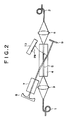
- the optical communication apparatus shown is formed as a repeating apparatus for supplying propagation light having communication information and transmitted thereto from an optical fiber 1 to another optical fiber 2.
- the propagation light here is light wavelength multiplexed, for example, in accordance with the WDM or DWDM system.
- the optical communication apparatus of the first embodiment includes a lens 3, a nonlinear optical crystal member 4 in which an optical waveguide 5 is formed, another lens 6, a YAG laser lot 7, mirrors 8 and 9, and a PD (photo-detector) array 10.
- Propagation light having communication information propagates along the optical waveguide 5 (for example, an optical waveguide element made of a lithium niobate material) formed by the nonlinear optical material 4 in a transmission line, more particularly, between the optical fibers 1 and 2.
- the optical waveguide 5 for example, an optical waveguide element made of a lithium niobate material
- the optical parts (YAG laser lot 7 and the mirrors 8 and 9) for irradiating a high-intensity laser beam from the outside of the optical waveguide 5 are arranged for the optical waveguide 5.
- the optical parts and the optical waveguide 5 are arranged such that an interaction between the propagation light having the communication information which propagates in the optical waveguide 5.
- the laser beam irradiated from the outside of the optical waveguide 5 by the YAG laser lot 7 and the mirrors 8 and 9 occurs such that light having wavelengths different from those of the propagation light having the communication information which propagates in the optical waveguide 5 is emitted to the outside of the optical waveguide 5.
- the PD array 10 is arranged outside the optical waveguide 5 and includes light receiving elements (photo-detectors) PD for converting the light emitted to the outside of the optical waveguide 5 into electric signals.
- the interaction between the propagation light having communication information which propagates in the optical waveguide 5 and the laser beam irradiated from the outside particularly is a phenomenon such as parametric oscillation based on a nonlinear optical constant of the nonlinear optical material 4.
- the interaction is an action wherein light is emitted with a wavelength and in a direction which satisfy a wave number vector Ko1 which depends upon a wave number vector Kf1 of the light which propagates in the transmission line and a wave number vector Kr of the light irradiated from the outside.
- the parametric oscillation phenomenon includes two phenomena of a frequency difference and a frequency sum.
- FIG. 3 illustrates a relationship of vectors where the phenomenon of the frequency difference is used.
- the parametric oscillation phenomenon is a phenomenon wherein light of a wave number vector determined by a wave number vector of light which propagates in the transmission line and a wave number vector of light irradiated from the outside is emitted externally. Therefore, even if the light irradiated from the outside has a single frequency, if another light having a different wavelength propagates in the transmission line, then the light is emitted externally with a wavelength and in a direction which satisfy a wave number vector Ko2 which depends upon a wave number vector Kf2 of the light which propagates in the transmission line and a wave number vector Kr of the light irradiated from the outside as seen from a wave number vector diagram of FIG. 4. Consequently, lights having wavelengths different from each other are emitted externally in directions corresponding to the wavelengths of the lights which propagate in the transmission line.
- the externally emitted light includes a temporal intensity distribution corresponding to a temporal intensity variation of the light propagating in the transmission line.
- temporal intensity variations for the individual wavelengths of the propagation lights which propagate in the transmission line that is, signals corresponding to communication information, are inputted to two light receiving elements PD1 and PD2 seen in FIG. 4.
- the light receiving elements PD1 and PD2 can read the optical information.
- the transmission line shown in FIGS. 3 and 4 corresponds to the optical waveguide 5, and propagation light having communication information is confined in the optical waveguide 5. Then, a laser beam having a high intensity is irradiated from the YAG laser lot 7 upon the optical waveguide 5. In this instance, the irradiated laser beam does not propagate in the optical waveguide 5, and therefore, is not condensed by the lens 6 and does not propagate to the optical fiber 2.
- temporal intensity variations of the individual wavelengths included in the propagation light which propagates in the optical waveguide 5, that is, signals corresponding to the individual multiplexed communication information, are inputted to a plurality of light receiving elements PD in the PD array 10.
- the optical communication apparatus of FIG. 1 can read several kinds of information multiplexed with different wavelengths without demultiplexing the multiplexed information.
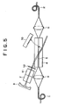
- FIG. 5 A configuration of another optical communication apparatus to which the present invention is supplied is shown in FIG. 5.
- the optical communication apparatus has a resonator configuration provided at a location at which a light irradiation section which irradiates light upon the optical waveguide 5 is provided, and an optical transmission line formed from a material having a nonlinear optical effect is arranged in the resonator.
- optical communication apparatus of FIG. 5 further includes lenses 3 and 6, an optical waveguide 5 and a PD array 10 similar to those of the optical communication apparatus described hereinabove with reference to FIG. 2.
- a YAG laser lot 7 a nonlinear optical crystal member 11, and mirrors 8 and 12 are provided as components of the light irradiation section which irradiates a laser beam from the outside upon the optical waveguide 5.
- the nonlinear optical crystal 11 arranged for the YAG laser lot 7 functions as a second harmonic production element.
- the nonlinear optical crystal element 11 which is a second harmonic production element is used to reduce the wavelength of the laser beam. If the wavelength of the laser beam is reduced by the reduction of the wavelength just described to convert the laser beam into a laser beam of a wavelength shorter than, for example, 1.064 microns, that is, of a higher frequency, a higher conversion efficiency can be achieved.
- FIG. 6 shows an optical communication system to which the present invention is applied.
- the optical communication system shown uses the optical information reading method of the optical communication apparatus shown in FIG. 2.
- the optical communication system uses the optical communication apparatus of FIG. 2 and includes an optical switch 22 connected to the optical fiber 2 shown in FIG. 2 for distributing light from the optical fiber 2 to an optical fiber 23 and another optical fiber 24, and an information reading apparatus 21 for supplying a switching driving signal CSW to the optical switch 22 to drive the optical switch 22.
- optical switch 22 although a particular configuration of the optical switch 22 is not shown in FIG. 6, a known optical switch such as an optical switch composed of a demultiplexer, a micro-mirror array and a multiplexer may be used as the optical switch 22.
- a known optical switch such as an optical switch composed of a demultiplexer, a micro-mirror array and a multiplexer may be used as the optical switch 22.
- a decoding operation of optical information is performed at a stage before signal light is introduced into the optical switch 22, that is, at a stage wherein signal light is propagating in the optical waveguide 5 of the nonlinear optical crystal 4 before it is introduced into the optical fiber 2.
- the information reading apparatus 21 can decode the signals obtained by the light receiving elements of the PD array 10 to read information of the multiplexed optical signals such as, for example, header information.
- the information reading apparatus 21 can discriminate output destinations of the optical signals of the different wavelengths and produce a driving signal CSW for the optical switch 22 in accordance with the output destinations.
- the decoding operation of the information is performed at an earlier stage when compared with an alternative case wherein the optical signals are demultiplexed to read the optical information after they have propagated in the optical fiber 2. Accordingly, driving of the optical switch 22 can be performed at an earlier stage. In other words, higher speed optical switching can be achieved.
- the optical communication system can be formed with a reduced size and at a reduced cost.
- FIG. 7 shows a further optical communication apparatus to which the present invention is applied.
- the optical communication apparatus shown uses a frequency sum of a parametric oscillation phenomenon.
- the optical communication apparatus includes similar components to those of the optical communication apparatus described hereinabove with reference to FIGS. 2 and 5.
- FIGS. 8 and 9 illustrate wave number vectors of the optical communication apparatus of FIG. 7.
- the optical communication apparatus of FIG. 7 externally emits light with a wavelength and in a direction which satisfy a wave number vector Ko1 which depends upon a wave number vector Kf1 of light propagating in the transmission line and a wave number vector Kr of light irradiated from the outside as seen in FIG. 8.
- the light irradiated from the outside has a single frequency
- the light is emitted externally with a wavelength and in a direction which satisfy a wave number vector Ko2 which depends upon a wave number vector Kf2 of the light which propagates in the transmission line and a wave number vector Kr of the light irradiated from the outside as seen from a wave number vector diagram of FIG. 8. Consequently, lights having wavelengths different from each other are emitted externally in directions corresponding to the wavelengths of the lights which propagate in the transmission line.
- the optical communication apparatus having the configuration described above with reference to FIG. 7 can read information of individual wavelengths from multiplexed optical signals propagating in the optical waveguide 5 by means of the light receiving elements PD of the PD array 10.
- the optical communication apparatus of FIG. 7 can be used to construct such an optical switching system as described hereinabove with reference to FIG. 6.
- Wavelength propagating in optical transmission line 1.550 microns
- Wavelength of irradiated light 1.064 microns
- Incident angle 10 degrees
- Wavelength of externally emitted light 3.08218 microns
- Emitting angle 3.43666 degrees
- Wavelength propagating in optical transmission line 1.552 microns
- Wavelength of irradiated light 1.064 microns
- Incident angle 10 degrees
- Wavelength of externally emitted light 3.07537 microns
- Emitting angle 3.444429 degrees
- Wavelength propagating in optical transmission line 1.550 microns
- Wavelength of irradiated light 0.532 microns Incident angle: 10 degrees
- Wavelength of emitting light 0.800402 microns Emitting angle: 6.62774 degrees
- Wavelength propagating in optical transmission line 1.552 microns
- Wavelength of irradiated light 0.532 microns
- Incident angle 10 degrees
- Wavelength of emitting light 0.799888 microns
- Emitting angle 6.63201 degrees
- Wavelength propagating in optical transmission line 1.550 microns
- Wavelength of irradiated light 1.064 microns Incident angle: 10 degrees
- Wavelength of emitting light 0.633237 microns
- Emitting angle 16.96416 degrees
- Wavelength propagating in optical transmission line 1.552 microns
- Wavelength of irradiated light 1.064 microns
- Incident angle 10 degrees
- Wavelength of externally emitted light 0.633568 microns
- Emitting angle 16.95501 degrees
- Wavelength propagating in optical transmission line 1.550 microns
- Wavelength of irradiated light 0.532 microns
- Incident angle 10 degrees
- Wavelength of externally emitted light 0.397211 microns
- Emitting angle 13.4486 degrees
- Wavelength propagating in optical transmission line 1.552 microns
- Wavelength of irradiated light 0.532 microns
- Incident angle 10 degrees
- Wavelength of externally emitted light 0.397341 microns
- Emitting angle 13.4441 degrees
Landscapes
- Engineering & Computer Science (AREA)
- Computer Networks & Wireless Communication (AREA)
- Optical Communication System (AREA)
- Optical Modulation, Optical Deflection, Nonlinear Optics, Optical Demodulation, Optical Logic Elements (AREA)
- Lasers (AREA)
Abstract
An optical switching system is disclosed which can achieve high speed optical switching with a simple configuration. Light from a light irradiation section (7, 8, 9) is irradiated into an optical transmission line (5) made of a material (4) having a nonlinear optical effect and disposed on the upstream side with respect to an optical switch (22) provided for performing switching of a transmission line (2) to cause the nonlinear optical effect to occur. Thereupon, light is emitted externally from the optical transmission line (5) by the nonlinear optical effect between the light irradiated by the light irradiation section (7, 8, 9) and light propagating in the optical transmission line (5). The light emitted is received by a light reception section (10) to acquire intensity information of the light propagating in the optical transmission line. The intensity information is used as driving signal (Csw) for driving the optical switch (22).
Description
- This invention relates to an optical communication apparatus, an optical communication information decoding method, an optical switching system and a driving method for an optical switching system, and more particularly to an optical communication apparatus, an optical communication information decoding method, an optical switching system and a driving method for an optical switching system suitable for use for a switching process of multiplexed optical signals.
- The field of optical communication has been developing rapidly together with the progress of the information-based society in recent years. In the field of optical communication, the progress is significant in the field of the enhancement in function beginning with the enhancement in transfer rate and the multiplexing of data.
- As a multiplexing technique, wavelength multiplexing techniques such as the WDM (Wavelength Division Multiplexing) and the DWDM (Dense Wavelength Division Multiplexing) have been developed.
- In such a situation as described above, also with regard to a switching technique required for a repeating point of an optical fiber transmission line (hereinafter referred to merely as optical fiber), specifications for higher performances such as higher speed operation of an optical switch are demanded.
- More particularly, it is demanded to raise the speed of an optical switch which quickly decodes header information included in information propagating in an optical fiber, that is, information in which a destination of information is recorded, and operates rapidly in response to the header information.
- However, in an environment of the WDM or the DWDM, information propagating in an optical fiber and including header information cannot be read before optical wavelengths are demultiplexed from one another. Therefore, an optical switching system at a repeating point of an optical fiber cannot be avoided to have such a configuration as shown in FIG. 1.
- FIG. 1 shows an optical switching system which distributes and outputs wavelength-multiplexed optical signals inputted from an
optical fiber 51 tooptical fibers - Referring to FIG. 1, wavelength-multiplexed light transmitted along the
optical fiber 51 in accordance with the WDM or DWDM system is demultiplexed for individual wavelengths by ademultiplexer 54 and individually received bylight reception units 55a to 55f.Information reading apparatus 56a to 56f read header information of information signals in the form of optical signals of the different wavelengths received by thelight reception units 55a to 55f, respectively. - The
information reading apparatus 56a to 56f discriminate destinations of the individual information signals based on the header information to select output destinations of the information signals and signal the information signals to lightemitting elements 57a to 57f orlight emitting elements 58a to 58f. - For example, if the
information reading apparatus 56a discriminates that the output destination of the pertaining information signal is theoptical fiber 52 side, then it outputs the information signal to thelight emitting element 57a. On the other hand, if theinformation reading apparatus 56a discriminates that the information signal is theoptical fiber 53 side, then it outputs the information signal to thelight emitting element 58a. - When each of the
light emitting elements 57a to 57f and thelight emitting elements 58a to 58f receives an information signal, it emits light of an optical signal of a predetermined wavelength corresponding to the information signal. - Optical signals of different wavelengths outputted from all or some of the
light emitting elements 57a to 57f are multiplexed in accordance with the WDM or DWDM system by amultiplexer 59 and signaled to theoptical fiber 52. On the other hand, optical signals of different wavelengths outputted from all or some of thelight emitting elements 58a to 58f are multiplexed in accordance with the WDM or DWDM system by amultiplexer 60 and signaled to theoptical fiber 53. - In this manner, at a repeating point of an optical fiber, a demultiplexer for demultiplexing wavelength-multiplexed light into different wavelengths used in the WDM or DWDM, light receiving elements for the individual wavelengths and a number of light emitting sources for the individual wavelengths equal to the number of fiber transmission lines used for transmission are required. Therefore, the optical switching system has a configuration of a great scale.
- Further, since the optical switching system is configured such that it uses a procedure including demultiplexing of multiplexed wavelengths, light reception and information reading in order to select transmission destinations, it has a limitation to satisfaction of the demand for high speed optical switching.
- It is an object of the present invention to provide a method and an apparatus which can decode information included in optical signals transmitted, for example, in accordance with the WDM or DWDM system without demultiplexing the optical signals.
- It is another object of the present invention to provide an optical switching system and a driving method for an optical switching system which can achieve high speed optical switching with a simple configuration.
- In order to attain the objects described above, according to the first aspect of the present invention, there is provided an optical communication apparatus which includes an optical transmission line made of a material having a nonlinear optical effect, a light irradiation section for irradiating light into the optical transmission line to cause the nonlinear optical effect to occur, and a light reception section for receiving light emitted externally from the optical transmission line by the nonlinear optical effect between the light irradiated into the optical transmission line by the light irradiation section and light propagating in the optical transmission line to acquire intensity information of the light propagating in the optical transmission line.
- According to the second aspect of the present invention, there is provided an optical communication information decoding method for an optical communication apparatus which includes an optical transmission line made of a material having a nonlinear optical effect, a light irradiation section for irradiating light into the optical transmission line to cause the nonlinear optical effect to occur, and a light reception section for receiving light emitted externally from the optical transmission line by the nonlinear optical effect of the optical transmission line, including the step of receiving the light emitted externally from the optical transmission line by the nonlinear optical effect between the light irradiated into the optical transmission line by the light irradiation section and light propagating in the optical transmission line by means of the light reception section to decode header information of the information propagating in the optical transmission line.
- According to the third aspect of the present invention, there is provided an optical switching system for switching a transmission line in response to information propagating in an optical transmission line which includes an optical switch for performing switching of a transmission line, an optical transmission line made of a material having a nonlinear optical effect and disposed on the upstream side with respect to the optical switch, a light irradiation section for irradiating light into the optical transmission line to cause the nonlinear optical effect to occur, a light reception section for receiving light emitted externally from the optical transmission line by the nonlinear optical effect between the light irradiated into the optical transmission line by the light irradiation section and light propagating in the optical transmission line to acquire intensity information of the light propagating in the optical transmission line, and driving means for producing a driving signal for the optical switch from the intensity information acquired by the light reception section.
- According to the fourth aspect of the present invention, there is provided a driving method for an optical switching system for switching a transmission line in response to information propagating in an optical transmission line, including the steps of irradiating light from a light irradiation section into an optical transmission line made of a material having a nonlinear optical effect and disposed on the upstream side with respect to an optical switch which performs switching of a transmission line, receiving light emitted externally from the optical transmission line by the nonlinear optical effect between the light irradiated by the light irradiation section and light propagating in the optical transmission line by means of a light reception section to acquire intensity information of the light propagating in the optical transmission line, and producing a driving signal for the optical switch based on the intensity information.
- In the optical communication apparatus, optical communication information decoding method, optical switching system and driving method for an optical switching system, the light emitted externally from the optical transmission line by the nonlinear optical effect may have a wavelength different from that of the light propagating in the optical transmission line.
- Where the light propagating in the optical transmission line has a plurality of wavelengths, the light emitted externally from the optical transmission line by the nonlinear optical effect may have a plurality of wavelengths corresponding to the plurality of wavelengths propagating in the optical transmission line.
- Where the light propagating in the optical transmission line has a plurality of wavelengths, the light emitted externally from the optical transmission line by the nonlinear optical effect may be emitted in a plurality of directions corresponding to the plurality of wavelengths propagating in the optical transmission line.
- Preferably, the light irradiated into the optical transmission line by the light irradiation section to cause the nonlinear optical effect to occur is a laser beam.
- The light irradiation section may include a resonator, in which an optical transmission line made of a material having a nonlinear optical effect is disposed.
- With the optical communication apparatus, optical communication information decoding method, optical switching system and driving method for an optical switching system, for example, where optical signals multiplexed with different wavelengths in accordance with the WDM system or the DWDM system are transmitted, information included in the optical signals can be decoded at a stage before they are demultiplexed from each other through the utilization of a nonlinear optical effect in the optical transmission line, and a switching operation for optical switching can be performed in response to the decoded information. Consequently, there is an advantage that a temporal intensity variation of the light propagating in the optical transmission line can be decoded for each of the wavelengths of the light signals before the light is demultiplexed.
- Further, even in an environment of a system wherein different wavelengths are involved such as the WDM system or the DWDM system, information of each wavelength, specifically header information, can be decoded without using a demultiplexer. Therefore, the processing time when an optical switch is driven can be reduced.
- Furthermore, the optical switching system can be formed in a simplified configuration because there is no necessity to prepare light emitting elements (light sources) for individually different wavelengths.
- The above and other objects, features and advantages of the present invention will become apparent from the following description and the appended claims, taken in conjunction with the accompanying drawings in which like parts or elements denoted by like reference symbols.
-
- FIG. 1 is a block diagram showing a configuration of a conventional optical switching system;
- FIG. 2 is a schematic view showing a configuration of an optical communication apparatus to which the present invention is applied;
- FIGS. 3 and 4 are wave number vector diagrams where a frequency difference of a parametric oscillation phenomenon is used in the optical communication apparatus of FIG. 2;
- FIG. 5 is a schematic view showing a configuration of another optical communication apparatus to which the present invention is applied;
- FIG. 6 is a schematic view showing a configuration of an optical switching system to which the present invention is applied;
- FIG. 7 is a schematic view showing a configuration of a further optical communication apparatus to which the present invention is applied; and
- FIGS. 8 and 9 are wave number vector diagrams where a frequency difference of a parametric oscillation phenomenon is used in the optical communication apparatus of FIG. 7.
- Referring to FIG. 2, there is shown an optical communication apparatus to which the present invention is applied. The optical communication apparatus shown is formed as a repeating apparatus for supplying propagation light having communication information and transmitted thereto from an
optical fiber 1 to anotheroptical fiber 2. - The propagation light here is light wavelength multiplexed, for example, in accordance with the WDM or DWDM system.
- The optical communication apparatus of the first embodiment includes a
lens 3, a nonlinearoptical crystal member 4 in which anoptical waveguide 5 is formed, anotherlens 6, aYAG laser lot 7,mirrors array 10. - Propagation light having communication information propagates along the optical waveguide 5 (for example, an optical waveguide element made of a lithium niobate material) formed by the nonlinear
optical material 4 in a transmission line, more particularly, between theoptical fibers - The optical parts (
YAG laser lot 7 and themirrors 8 and 9) for irradiating a high-intensity laser beam from the outside of theoptical waveguide 5 are arranged for theoptical waveguide 5. - The optical parts and the
optical waveguide 5 are arranged such that an interaction between the propagation light having the communication information which propagates in theoptical waveguide 5. The laser beam irradiated from the outside of theoptical waveguide 5 by theYAG laser lot 7 and themirrors optical waveguide 5 is emitted to the outside of theoptical waveguide 5. - The
PD array 10 is arranged outside theoptical waveguide 5 and includes light receiving elements (photo-detectors) PD for converting the light emitted to the outside of theoptical waveguide 5 into electric signals. - Here, the interaction between the propagation light having communication information which propagates in the
optical waveguide 5 and the laser beam irradiated from the outside particularly is a phenomenon such as parametric oscillation based on a nonlinear optical constant of the nonlinearoptical material 4. As seen in FIG. 3, the interaction is an action wherein light is emitted with a wavelength and in a direction which satisfy a wave number vector Ko1 which depends upon a wave number vector Kf1 of the light which propagates in the transmission line and a wave number vector Kr of the light irradiated from the outside. - It is to be noted that the parametric oscillation phenomenon includes two phenomena of a frequency difference and a frequency sum. FIG. 3 illustrates a relationship of vectors where the phenomenon of the frequency difference is used.
- The parametric oscillation phenomenon is a phenomenon wherein light of a wave number vector determined by a wave number vector of light which propagates in the transmission line and a wave number vector of light irradiated from the outside is emitted externally. Therefore, even if the light irradiated from the outside has a single frequency, if another light having a different wavelength propagates in the transmission line, then the light is emitted externally with a wavelength and in a direction which satisfy a wave number vector Ko2 which depends upon a wave number vector Kf2 of the light which propagates in the transmission line and a wave number vector Kr of the light irradiated from the outside as seen from a wave number vector diagram of FIG. 4. Consequently, lights having wavelengths different from each other are emitted externally in directions corresponding to the wavelengths of the lights which propagate in the transmission line.
- Further, if the light irradiated from the outside is light fixed in time, then the externally emitted light includes a temporal intensity distribution corresponding to a temporal intensity variation of the light propagating in the transmission line.
- In particular, temporal intensity variations for the individual wavelengths of the propagation lights which propagate in the transmission line, that is, signals corresponding to communication information, are inputted to two light receiving elements PD1 and PD2 seen in FIG. 4.
- Then, even if the lights which propagate in the transmission line are week, if the light irradiated from the outside has a high intensity and there is a situation that the light which transmits in the transmission line is confined in the transmission line, then the light receiving elements PD1 and PD2 can read the optical information.
- If the action described above is adapted to the configuration of FIG. 2, then the transmission line shown in FIGS. 3 and 4 corresponds to the
optical waveguide 5, and propagation light having communication information is confined in theoptical waveguide 5. Then, a laser beam having a high intensity is irradiated from theYAG laser lot 7 upon theoptical waveguide 5. In this instance, the irradiated laser beam does not propagate in theoptical waveguide 5, and therefore, is not condensed by thelens 6 and does not propagate to theoptical fiber 2. - Accordingly, temporal intensity variations of the individual wavelengths included in the propagation light which propagates in the
optical waveguide 5, that is, signals corresponding to the individual multiplexed communication information, are inputted to a plurality of light receiving elements PD in thePD array 10. - The optical communication apparatus of FIG. 1 can read several kinds of information multiplexed with different wavelengths without demultiplexing the multiplexed information.
- A configuration of another optical communication apparatus to which the present invention is supplied is shown in FIG. 5. Referring to FIG. 5, the optical communication apparatus has a resonator configuration provided at a location at which a light irradiation section which irradiates light upon the
optical waveguide 5 is provided, and an optical transmission line formed from a material having a nonlinear optical effect is arranged in the resonator. - It is to be noted that the optical communication apparatus of FIG. 5 further includes
lenses optical waveguide 5 and aPD array 10 similar to those of the optical communication apparatus described hereinabove with reference to FIG. 2. - In the optical communication apparatus of FIG. 5, a
YAG laser lot 7, a nonlinearoptical crystal member 11, and mirrors 8 and 12 are provided as components of the light irradiation section which irradiates a laser beam from the outside upon theoptical waveguide 5. The nonlinearoptical crystal 11 arranged for theYAG laser lot 7 functions as a second harmonic production element. - In particular, in the optical communication apparatus of FIG. 5, the nonlinear
optical crystal element 11 which is a second harmonic production element is used to reduce the wavelength of the laser beam. If the wavelength of the laser beam is reduced by the reduction of the wavelength just described to convert the laser beam into a laser beam of a wavelength shorter than, for example, 1.064 microns, that is, of a higher frequency, a higher conversion efficiency can be achieved. - FIG. 6 shows an optical communication system to which the present invention is applied. The optical communication system shown uses the optical information reading method of the optical communication apparatus shown in FIG. 2.
- Referring to FIG. 6, the optical communication system uses the optical communication apparatus of FIG. 2 and includes an
optical switch 22 connected to theoptical fiber 2 shown in FIG. 2 for distributing light from theoptical fiber 2 to anoptical fiber 23 and anotheroptical fiber 24, and aninformation reading apparatus 21 for supplying a switching driving signal CSW to theoptical switch 22 to drive theoptical switch 22. - It is to be noted that, although a particular configuration of the
optical switch 22 is not shown in FIG. 6, a known optical switch such as an optical switch composed of a demultiplexer, a micro-mirror array and a multiplexer may be used as theoptical switch 22. - In the optical communication system shown in FIG. 6, a decoding operation of optical information is performed at a stage before signal light is introduced into the
optical switch 22, that is, at a stage wherein signal light is propagating in theoptical waveguide 5 of the nonlinearoptical crystal 4 before it is introduced into theoptical fiber 2. - In particular, since, as described hereinabove in connection with the optical communication apparatus of FIG. 2, intensity information of optical signals of different wavelengths which propagate in the
optical waveguide 5 is inputted individually to the light receiving elements of thePD array 10, theinformation reading apparatus 21 can decode the signals obtained by the light receiving elements of thePD array 10 to read information of the multiplexed optical signals such as, for example, header information. - Accordingly, the
information reading apparatus 21 can discriminate output destinations of the optical signals of the different wavelengths and produce a driving signal CSW for theoptical switch 22 in accordance with the output destinations. - Since, in the optical switching system having such a configuration as described above, decoding of optical information of optical signals of signal light is performed at a stage before the optical signals are inputted to the
optical switch 22, the decoding operation of the information is performed at an earlier stage when compared with an alternative case wherein the optical signals are demultiplexed to read the optical information after they have propagated in theoptical fiber 2. Accordingly, driving of theoptical switch 22 can be performed at an earlier stage. In other words, higher speed optical switching can be achieved. - Further, in the optical switching system shown in FIG. 6, the necessity for preparation of a light source for each wavelength is eliminated when compared with the conventional optical switching system shown in FIG. 1. Therefore, the optical communication system can be formed with a reduced size and at a reduced cost.
- It is to be noted that, while it is described that a frequency difference of a parametric oscillation phenomenon is used in the optical communication apparatus and the optical switching system according to the present invention described above, the present invention is not limited to such optical communication apparatus or optical switching system in which a frequency difference is used as described above.
- FIG. 7 shows a further optical communication apparatus to which the present invention is applied. Referring to FIG. 7, the optical communication apparatus shown uses a frequency sum of a parametric oscillation phenomenon. The optical communication apparatus includes similar components to those of the optical communication apparatus described hereinabove with reference to FIGS. 2 and 5. FIGS. 8 and 9 illustrate wave number vectors of the optical communication apparatus of FIG. 7.
- Also the optical communication apparatus of FIG. 7 externally emits light with a wavelength and in a direction which satisfy a wave number vector Ko1 which depends upon a wave number vector Kf1 of light propagating in the transmission line and a wave number vector Kr of light irradiated from the outside as seen in FIG. 8.
- Further, even if the light irradiated from the outside has a single frequency, if another light having a different wavelength propagates in the transmission line, then the light is emitted externally with a wavelength and in a direction which satisfy a wave number vector Ko2 which depends upon a wave number vector Kf2 of the light which propagates in the transmission line and a wave number vector Kr of the light irradiated from the outside as seen from a wave number vector diagram of FIG. 8. Consequently, lights having wavelengths different from each other are emitted externally in directions corresponding to the wavelengths of the lights which propagate in the transmission line.
- From FIGS. 8 and 9, it can be recognized that, even where a frequency sum of a parametric oscillation phenomenon is used, by irradiating a laser beam having a single frequency and fixed in time from the outside, a temporal intensity variation for each wavelength propagating in a transmission line can be detected by means of light receiving elements which are provided externally to monitor lights emitted externally with wavelengths and in directions different among different wavelengths from an optical waveguide element made of a nonlinear optical material.
- Accordingly, also the optical communication apparatus having the configuration described above with reference to FIG. 7 can read information of individual wavelengths from multiplexed optical signals propagating in the
optical waveguide 5 by means of the light receiving elements PD of thePD array 10. Naturally, the optical communication apparatus of FIG. 7 can be used to construct such an optical switching system as described hereinabove with reference to FIG. 6. - In the following, examples of the wavelength and the direction of externally emitted light with respect to the wavelength and the incident angle of incident light are described with regard to two cases including a case wherein a frequency difference of a parametric oscillation phenomenon is used and another case wherein a frequency sum of a parameter oscillation phenomenon is used.
- Wavelength propagating in optical transmission line: 1.550 microns
Wavelength of irradiated light: 1.064 microns
Incident angle: 10 degrees
Wavelength of externally emitted light: 3.08218 microns
Emitting angle: 3.43666 degrees - Wavelength propagating in optical transmission line: 1.552 microns
Wavelength of irradiated light: 1.064 microns
Incident angle: 10 degrees
Wavelength of externally emitted light: 3.07537 microns
Emitting angle: 3.444429 degrees
Position difference corresponding towavelength difference 2 nm of propagating light where light receiving element is disposed at position spaced rearwardly by 10 mm from optical waveguide element: 369 microns - Wavelength propagating in optical transmission line: 1.550 microns
Wavelength of irradiated light: 0.532 microns
Incident angle: 10 degrees
Wavelength of emitting light: 0.800402 microns
Emitting angle: 6.62774 degrees - Wavelength propagating in optical transmission line: 1.552 microns
Wavelength of irradiated light: 0.532 microns
Incident angle: 10 degrees
Wavelength of emitting light: 0.799888 microns
Emitting angle: 6.63201 degrees
Position difference corresponding towavelength difference 2 nm of propagating light where light receiving element is disposed at position spaced rearwardly by 10 mm from optical waveguide element: 56 microns - Wavelength propagating in optical transmission line: 1.550 microns
Wavelength of irradiated light: 1.064 microns
Incident angle: 10 degrees
Wavelength of emitting light: 0.633237 microns
Emitting angle: 16.96416 degrees - Wavelength propagating in optical transmission line: 1.552 microns
Wavelength of irradiated light: 1.064 microns
Incident angle: 10 degrees
Wavelength of externally emitted light: 0.633568 microns
Emitting angle: 16.95501 degrees
Position difference corresponding towavelength difference 2 nm of propagating light where light receiving element is disposed at position spaced rearwardly by 10 mm from optical waveguide element: 188 microns - Wavelength propagating in optical transmission line: 1.550 microns
Wavelength of irradiated light: 0.532 microns
Incident angle: 10 degrees
Wavelength of externally emitted light: 0.397211 microns
Emitting angle: 13.4486 degrees - Wavelength propagating in optical transmission line: 1.552 microns
Wavelength of irradiated light: 0.532 microns
Incident angle: 10 degrees
Wavelength of externally emitted light: 0.397341 microns
Emitting angle: 13.4441 degrees
Position difference corresponding towavelength difference 2 nm of propagating light where light receiving element is disposed at position spaced rearwardly by 10 mm from optical waveguide element: 144 microns - According to the accuracy in production of light receiving elements at present, it is easy to produce light receiving elements of the size of approximately 10 microns. Therefore, from the results of the calculation above, it can be seen that a sufficient resolution in position for wavelengths propagating in the
optical waveguide 5 is obtained. In other words, information propagating in theoptical waveguide 5 can be read for each of wavelengths of the light as described hereinabove in connection with the embodiments of the present invention. - While preferred embodiments of the present invention have been described using specific terms, such description is for illustrative purposes only, and it is to be understood that changes and variations may be made without departing from the scope of the following claims.
Claims (24)
- An optical communication apparatus, comprising:an optical transmission line (5) made of a material (4) having a nonlinear optical effect;a light irradiation section (7, 8, 9) for irradiating light into said optical transmission line (5) to cause the nonlinear optical effect to occur; anda light reception section (10) for receiving light emitted externally from said optical transmission line (5) by the nonlinear optical effect between the light irradiated into said optical transmission line by said light irradiation section (7, 8, 9) and light propagating in said optical transmission line to acquire intensity information of the light propagating in said optical transmission line (5).
- An optical communication apparatus according to claim 1, wherein the light emitted externally from said optical transmission line (5) by the nonlinear optical effect has a wavelength different from that of the light propagating in said optical transmission line.
- An optical communication apparatus according to claim 1, wherein the light propagating in said optical transmission line (5) has a plurality of wavelengths, and the light emitted externally from said optical transmission line by the nonlinear optical effect has a plurality of wavelengths corresponding to the plurality of wavelengths propagating in said optical transmission line.
- An optical communication apparatus according to claim 1, wherein the light propagating in said optical transmission line (5) has a plurality of wavelengths, and the light emitted externally from said optical transmission line by the nonlinear optical effect is emitted in a plurality of directions corresponding to the plurality of wavelengths propagating in said optical transmission line.
- An optical communication apparatus according to claim 1, wherein the light irradiated into said optical transmission line (5) by said light irradiation section (7, 8, 9) to cause the nonlinear optical effect to occur is a laser beam.
- An optical communication apparatus according to claim 1, wherein said light irradiation section includes a resonator (11), in which an optical transmission line made of a material having a nonlinear optical effect is disposed.
- An optical communication information decoding method for an optical communication apparatus which includes an optical transmission line (5) made of a material (4) having a nonlinear optical effect, a light irradiation section (7, 8, 9) for irradiating light into said optical transmission line to cause the nonlinear optical effect to occur, and a light reception section (10) for receiving light emitted externally from said optical transmission line by the nonlinear optical effect of said optical transmission line, comprising the step of:receiving the light emitted externally from said optical transmission line (5) by the nonlinear optical effect between the light irradiated into said optical transmission line by said light irradiation section (7, 8, 9) and light propagating in said optical transmission line by means of said light reception section (10) to decode header information of the information propagating in said optical transmission line.
- An optical communication information decoding method according to claim 7, wherein the light emitted externally from said optical transmission line (5) by the nonlinear optical effect has a wavelength different from that of the light propagating in said optical transmission line.
- An optical communication information decoding method according to claim 7, wherein the light propagating in said optical transmission line (5) has a plurality of wavelengths, and the light emitted externally from said optical transmission line by the nonlinear optical effect has a plurality of wavelengths corresponding to the plurality of wavelengths propagating in said optical transmission line.
- An optical communication information decoding method according to claim 7, wherein the light propagating in said optical transmission line (5) has a plurality of wavelengths, and the light emitted externally from said optical transmission line by the nonlinear optical effect is emitted in a plurality of directions corresponding to the plurality of wavelengths propagating in said optical transmission line.
- An optical communication information decoding method according to claim 7, wherein the light irradiated into said optical transmission line (5) by said light irradiation section (7, 8, 9) to cause the nonlinear optical effect to occur is a laser beam.
- An optical communication information decoding method according to claim 7, wherein said light irradiation section includes a resonator (11), in which an optical transmission line made of a material having a nonlinear optical effect is disposed.
- An optical switching system for switching a transmission line in response to information propagating in an optical transmission line, comprising:an optical switch (22) for performing switching of a transmission line (2);an optical transmission line (5) made of a material (4) having a nonlinear optical effect and disposed on the upstream side with respect to said optical switch;a light irradiation section (7, 8, 9) for irradiating light into said optical transmission line to cause the nonlinear optical effect to occur;a light reception section (10) for receiving light emitted externally from said optical transmission line (5) by the nonlinear optical effect between the light irradiated into said optical transmission line by said light irradiation section (7, 8, 9) and light propagating in said optical transmission line to acquire intensity information of the light propagating in said optical transmission line; anddriving means (21) for producing a driving signal for said optical switch (22) from the intensity information acquired by said light reception section (10).
- An optical switching system according to claim 13, wherein the light emitted externally from said optical transmission line (5) by the nonlinear optical effect has a wavelength different from that of the light propagating in said optical transmission line.
- An optical switching system according to claim 13, wherein the light propagating in said optical transmission line (5) has a plurality of wavelengths, and the light emitted externally from said optical transmission line by the nonlinear optical effect has a plurality of wavelengths corresponding to the plurality of wavelengths propagating in said optical transmission line.
- An optical switching system according to claim 13, wherein the light propagating in said optical transmission line (5) has a plurality of wavelengths, and the light emitted externally from said optical transmission line by the nonlinear optical effect is emitted in a plurality of directions corresponding to the plurality of wavelengths propagating in said optical transmission line.
- An optical switching system according to claim 13, wherein the light irradiated into said optical transmission line (5) by said light irradiation section to cause the nonlinear optical effect to occur is a laser beam.
- An optical switching system according to claim 13, wherein said light irradiation section includes a resonator (11), in which an optical transmission line made of a material having a nonlinear optical effect is disposed.
- A driving method for an optical switching system for switching a transmission line (2) in response to information propagating in an optical transmission line, comprising the steps of:irradiating light from a light irradiation section (7, 8, 9) into an optical transmission line (5) made of a material (4) having a nonlinear optical effect and disposed on the upstream side with respect to an optical switch (22) which performs switching of a transmission line;receiving light emitted externally from said optical transmission line by the nonlinear optical effect between the light irradiated by said light irradiation section (7, 8, 9) and light propagating in said optical transmission line (5) by means of a light reception section (10) to acquire intensity information of the light propagating in said optical transmission line; andproducing a driving signal (Csw) for said optical switch based on the intensity information.
- A driving method for an optical switching system according to claim 19, wherein the light emitted externally from said optical transmission line (5) by the nonlinear optical effect has a wavelength different from that of the light propagating in said optical transmission line.
- A driving method for an optical switching system according to claim 19, wherein the light propagating in said optical transmission line (5) has a plurality of wavelengths, and the light emitted externally from said optical transmission line by the nonlinear optical effect has a plurality of wavelengths corresponding to the plurality of wavelengths propagating in said optical transmission line.
- A driving method for an optical switching system according to claim 19, wherein the light propagating in said optical transmission line (5) has a plurality of wavelengths, and the light emitted externally from said optical transmission line by the nonlinear optical effect is emitted in a plurality of directions corresponding to the plurality of wavelengths propagating in said optical transmission line.
- A driving method for an optical switching system according to claim 19, wherein the light irradiated into said optical transmission line (5) by said light irradiation section (7, 8, 9) to cause the nonlinear optical effect to occur is a laser beam.
- A driving method for an optical switching system according to claim 19, wherein said light irradiation section includes a resonator (11), in which an optical transmission line made of a material having a nonlinear optical effect is disposed.
Applications Claiming Priority (2)
| Application Number | Priority Date | Filing Date | Title |
|---|---|---|---|
| JP2001223056 | 2001-07-24 | ||
| JP2001223056A JP2003037318A (en) | 2001-07-24 | 2001-07-24 | Optical communication device, optical communication information decoding method, optical switching system, optical switching system driving method |
Publications (1)
| Publication Number | Publication Date |
|---|---|
| EP1280293A1 true EP1280293A1 (en) | 2003-01-29 |
Family
ID=19056449
Family Applications (1)
| Application Number | Title | Priority Date | Filing Date |
|---|---|---|---|
| EP02291863A Withdrawn EP1280293A1 (en) | 2001-07-24 | 2002-07-24 | Optical fiber communication apparatus and data decoding method using the apparatus based on a nonlinear optical effect |
Country Status (3)
| Country | Link |
|---|---|
| US (2) | US7092632B2 (en) |
| EP (1) | EP1280293A1 (en) |
| JP (1) | JP2003037318A (en) |
Families Citing this family (2)
| Publication number | Priority date | Publication date | Assignee | Title |
|---|---|---|---|---|
| JP2003037318A (en) * | 2001-07-24 | 2003-02-07 | Sony Corp | Optical communication device, optical communication information decoding method, optical switching system, optical switching system driving method |
| US20140115483A1 (en) * | 2012-10-18 | 2014-04-24 | Aol Inc. | Systems and methods for processing and organizing electronic content |
Citations (6)
| Publication number | Priority date | Publication date | Assignee | Title |
|---|---|---|---|---|
| US5488501A (en) * | 1992-04-09 | 1996-01-30 | British Telecommunications Plc | Optical processing system |
| EP0697775A2 (en) * | 1994-08-15 | 1996-02-21 | Nippon Telegraph And Telephone Corporation | Multiple-channel all-optical TDM-WDM converter and multiple-channel all-optical TDM demultiplexer |
| US5680247A (en) * | 1995-06-07 | 1997-10-21 | Nec Corporation | Optical amplification monitoring apparatus |
| WO1998031184A1 (en) * | 1997-01-07 | 1998-07-16 | Tellium, Inc. | Hybrid wavelength-interchanging cross-connect |
| WO2000004668A1 (en) * | 1998-07-17 | 2000-01-27 | Telcordia Technologies, Inc. | High-throughput, low-latency next generation internet networks using optical label switching |
| WO2002046837A2 (en) * | 2000-12-05 | 2002-06-13 | Fraunhofer-Gesellschaft zur Förderung der angewandten Forschung e.V. | Optical system |
Family Cites Families (5)
| Publication number | Priority date | Publication date | Assignee | Title |
|---|---|---|---|---|
| US6810211B1 (en) * | 1999-09-08 | 2004-10-26 | Alcatel | Preferred WDM packet-switched router architecture and method for generating same |
| JP3374174B2 (en) * | 1999-12-15 | 2003-02-04 | 独立行政法人通信総合研究所 | Packet routing method for photonic network and packet router for photonic network |
| JP2001244530A (en) * | 2000-02-28 | 2001-09-07 | Inst Of Physical & Chemical Res | Ultrashort pulse laser oscillator |
| US6819807B2 (en) * | 2000-08-23 | 2004-11-16 | Board Of Regents, The University Of Texas System | Optical correlator using spatial light modulator illumination |
| JP2003037318A (en) | 2001-07-24 | 2003-02-07 | Sony Corp | Optical communication device, optical communication information decoding method, optical switching system, optical switching system driving method |
-
2001
- 2001-07-24 JP JP2001223056A patent/JP2003037318A/en not_active Abandoned
-
2002
- 2002-07-19 US US10/198,130 patent/US7092632B2/en not_active Expired - Fee Related
- 2002-07-24 EP EP02291863A patent/EP1280293A1/en not_active Withdrawn
-
2006
- 2006-05-16 US US11/434,119 patent/US7382980B2/en not_active Expired - Fee Related
Patent Citations (6)
| Publication number | Priority date | Publication date | Assignee | Title |
|---|---|---|---|---|
| US5488501A (en) * | 1992-04-09 | 1996-01-30 | British Telecommunications Plc | Optical processing system |
| EP0697775A2 (en) * | 1994-08-15 | 1996-02-21 | Nippon Telegraph And Telephone Corporation | Multiple-channel all-optical TDM-WDM converter and multiple-channel all-optical TDM demultiplexer |
| US5680247A (en) * | 1995-06-07 | 1997-10-21 | Nec Corporation | Optical amplification monitoring apparatus |
| WO1998031184A1 (en) * | 1997-01-07 | 1998-07-16 | Tellium, Inc. | Hybrid wavelength-interchanging cross-connect |
| WO2000004668A1 (en) * | 1998-07-17 | 2000-01-27 | Telcordia Technologies, Inc. | High-throughput, low-latency next generation internet networks using optical label switching |
| WO2002046837A2 (en) * | 2000-12-05 | 2002-06-13 | Fraunhofer-Gesellschaft zur Förderung der angewandten Forschung e.V. | Optical system |
Also Published As
| Publication number | Publication date |
|---|---|
| JP2003037318A (en) | 2003-02-07 |
| US20030021027A1 (en) | 2003-01-30 |
| US20060245760A1 (en) | 2006-11-02 |
| US7382980B2 (en) | 2008-06-03 |
| US7092632B2 (en) | 2006-08-15 |
Similar Documents
| Publication | Publication Date | Title |
|---|---|---|
| JP4448542B2 (en) | High bit rate optical communication over multimode fiber | |
| EP3221729A1 (en) | Planar lightwave circuit active connector | |
| CN104838309A (en) | Optical device | |
| CN106461868B (en) | Multicore multimode fibre coupling device | |
| WO2004019179A2 (en) | Apparatus and method for generating a mode-scrambled optical signal using a vcsel array | |
| JPH10307228A (en) | Line monitor and optical amplifier using the monitor | |
| JP2003241006A (en) | Optical demultiplexer and optical multiplexer for wavelength division multiplex communication | |
| KR20170010478A (en) | Optical transmitting/receiving apparatus for input/output mode control and optical transmission system using the same | |
| EP1280293A1 (en) | Optical fiber communication apparatus and data decoding method using the apparatus based on a nonlinear optical effect | |
| JP6521062B2 (en) | Optical signal modulator and system | |
| US7019907B2 (en) | Integrated lithium niobate based optical transmitter | |
| JP2007011104A (en) | Light beam control device and stereoscopic image display device using the same | |
| JP2010175875A (en) | Optical module and method of adjusting light beam direction of optical module | |
| JP6979190B2 (en) | Spatial mode multiplex control technology | |
| EP1022869A1 (en) | Emergency equipement for wavelength multiplexed light sources | |
| WO2005078970A1 (en) | Optical transmission system | |
| JP2010197459A (en) | Optical multiplexer and light source device | |
| CN114744480B (en) | Optical Distributed Amplification Structure | |
| JP4484021B2 (en) | Multi-wavelength light source | |
| JPS62170932A (en) | Multiplex wavelength transmission system | |
| JP3116780B2 (en) | Optical multiplexer / demultiplexer | |
| JP2004037553A (en) | Crosstalk improved module and its usage | |
| JP2002111597A (en) | Optical transmitter | |
| JP2007078836A (en) | Optical coupling system for optical communication and optical communication system provided therewith | |
| Fontaine | Integrated Photonics for Space-Division Multiplexing |
Legal Events
| Date | Code | Title | Description |
|---|---|---|---|
| PUAI | Public reference made under article 153(3) epc to a published international application that has entered the european phase |
Free format text: ORIGINAL CODE: 0009012 |
|
| AK | Designated contracting states |
Designated state(s): AT BE BG CH CY CZ DE DK EE ES FI FR GB GR IE IT LI LU MC NL PT SE SK TR |
|
| AX | Request for extension of the european patent |
Extension state: AL LT LV MK RO SI |
|
| 17P | Request for examination filed |
Effective date: 20030704 |
|
| AKX | Designation fees paid |
Designated state(s): DE FR GB |
|
| 17Q | First examination report despatched |
Effective date: 20050126 |
|
| STAA | Information on the status of an ep patent application or granted ep patent |
Free format text: STATUS: THE APPLICATION IS DEEMED TO BE WITHDRAWN |
|
| 18D | Application deemed to be withdrawn |
Effective date: 20110201 |