EP1280291A2 - System and method for monitoring receiving portion in wireless base station system, and recording medium for the monitoring program - Google Patents
System and method for monitoring receiving portion in wireless base station system, and recording medium for the monitoring program Download PDFInfo
- Publication number
- EP1280291A2 EP1280291A2 EP02016288A EP02016288A EP1280291A2 EP 1280291 A2 EP1280291 A2 EP 1280291A2 EP 02016288 A EP02016288 A EP 02016288A EP 02016288 A EP02016288 A EP 02016288A EP 1280291 A2 EP1280291 A2 EP 1280291A2
- Authority
- EP
- European Patent Office
- Prior art keywords
- value
- receiving
- base station
- wireless base
- computed
- Prior art date
- Legal status (The legal status is an assumption and is not a legal conclusion. Google has not performed a legal analysis and makes no representation as to the accuracy of the status listed.)
- Withdrawn
Links
- 238000000034 method Methods 0.000 title claims description 30
- 238000012544 monitoring process Methods 0.000 title claims description 27
- 238000001514 detection method Methods 0.000 claims abstract description 32
- 238000012545 processing Methods 0.000 claims abstract description 16
- 230000007274 generation of a signal involved in cell-cell signaling Effects 0.000 claims description 7
- 238000010586 diagram Methods 0.000 description 20
- 230000010355 oscillation Effects 0.000 description 19
- 230000003321 amplification Effects 0.000 description 8
- 238000003199 nucleic acid amplification method Methods 0.000 description 8
- 238000005259 measurement Methods 0.000 description 6
- 238000004891 communication Methods 0.000 description 5
- 238000005562 fading Methods 0.000 description 4
- 230000035945 sensitivity Effects 0.000 description 4
- 230000005540 biological transmission Effects 0.000 description 2
- 230000006866 deterioration Effects 0.000 description 2
- 230000005684 electric field Effects 0.000 description 2
- 230000007257 malfunction Effects 0.000 description 2
- 238000013461 design Methods 0.000 description 1
- 238000010295 mobile communication Methods 0.000 description 1
- 230000008054 signal transmission Effects 0.000 description 1
Images




Classifications
-
- H—ELECTRICITY
- H04—ELECTRIC COMMUNICATION TECHNIQUE
- H04B—TRANSMISSION
- H04B17/00—Monitoring; Testing
- H04B17/40—Monitoring; Testing of relay systems
-
- H—ELECTRICITY
- H04—ELECTRIC COMMUNICATION TECHNIQUE
- H04B—TRANSMISSION
- H04B17/00—Monitoring; Testing
- H04B17/30—Monitoring; Testing of propagation channels
- H04B17/309—Measuring or estimating channel quality parameters
- H04B17/318—Received signal strength
- H04B17/327—Received signal code power [RSCP]
Definitions
- the present invention relates to a system and method for monitoring a receiving portion in a wireless base station system and to a recording medium on which a monitoring program is recorded. More particularly, the present invention relates to a system and method for monitoring a receiving portion in a wireless base station system which performs communication with mobile terminals and to a recording medium on which a monitoring program is recorded.
- NF noise figure
- WCDMA wideband code division multiple access
- the technique disclosed in the related art document 1 relates to a device for detecting a fault in a high-sensitivity wireless portion installed outside a building.
- a detection of a fault in an outdoor receiver is performed by making determination using monitoring means 35 as to whether a pilot signal level is lower than a reference value.
- the invention disclosed in this document differs from the present invention in that it does not use the bit error rate (BER) as a determination criterion.
- BER bit error rate
- the technique disclosed in the related art document 2 uses means for detecting a fading pitch from a reception signal, BER detection means, received input level measuring means in a mobile wireless portion, and appropriate moving speed detection means for deriving a current appropriate moving speed from fading pitch detection information, BER, and received input level information.
- This technique enables a user to reduce a deterioration in communication quality due to fading by considering the derived moving speed.
- the invention disclosed in this document differs from the present invention in that it is concerned with a mobile wireless portion and aims to reduce deterioration in communication quality due to fading.
- the technique disclosed in the related art document 3 relates to a device for detecting a fault in a receiver amplifier installed outside a building and makes fault determination by preparing a fault detection reference value from a standard attenuation value relating to leakage of a transmitted signal from a transmitter to a receiving circuit in an antenna-sharing unit, a standard amplification value of the receiver amplifier, and transmission power information of the transmitter, and by comparing electric field intensity information output from an electric field detecting portion with the reference value.
- the invention disclosed in this document differs from the present invention in that it uses no pilot signal.
- An object of the present invention is to provide, as means capable of solving the above-described problem, a system and method for monitoring a receiving portion in a wireless base station system in which the NF and feeder loss of an outdoor receiver amplifier are automatically computed to report a correct level of received total wideband power (RTWP).
- RCWP total wideband power
- a receiving portion monitoring system in a wireless base station system including receiving and amplifying means for amplifying a received signal, and wireless base station means for demodulating a signal output from the receiving and amplifying means and for detecting a fault in the receiving and amplifying means on the basis of the demodulated signal, the receiving and amplifying means including a pilot signal generation portion which generates a pilot signal for detection of a fault, and an amplifier which amplifies the received signal and the pilot signal, and the wireless base station means including a wireless portion which demodulates a signal output from the amplifier and computes a received signal code power (RSCP) value and a BER value from the demodulated signal, a detection portion which computes a feeder loss and an NF value between the receiving and amplifying means and the wireless base station means from the computed RSCP and BER values, and an RTWP processing portion which outputs an RTWP value including a value relating to the
- RSCP received signal code power
- a receiving portion monitoring method for a wireless base station system including receiving and amplifying means for amplifying a received signal, and wireless base station means for demodulating a signal output from the receiving and amplifying means and for detecting a fault in the receiving and amplifying means on the basis of the demodulated signal, the receiving and amplifying means including a pilot signal generation portion which generates a pilot signal for detection of a fault, and an amplifier which amplifies the received signal and the pilot signal, the method comprising, as steps to be performed in the wireless base station means, a first step of demodulating a signal output from the amplifier and computing an RSCP value and a BER value from the demodulated signal, a second step of computing a feeder loss and an NF value between the receiving and amplifying means and the wireless base station means from the computed RSCP and BER values, and a third step of outputting an RTWP value including a value relating to the NF value detected in the second step.
- a recording medium on which is recorded a program for making a computer carry out a receiving portion monitoring method for a wireless base station system including receiving and amplifying means for amplifying a received signal, and wireless base station means for demodulating a signal output from the receiving and amplifying means and for detecting a fault in the receiving and amplifying means on the basis of the demodulated signal, the receiving and amplifying means including a pilot signal generation portion which generates a pilot signal for detection of a fault, and an amplifier which amplifies the received signal and the pilot signal, the wireless base station means including the recording medium, the program including a first step of demodulating a signal output from the amplifier and computing an RSCP value and a BER value from the demodulated signal, a second step of computing a feeder loss and an NF value between the receiving and amplifying means and the wireless base station means from the computed RSCP and BER values, and a third step of outputting an RTWP value including a
- the system is arranged to automatically compute the NF of the outdoor receiver amplifier and the loss in the feeder and to report correct RTWP, thus solving the above-described problem.
- FIG. 1 is a diagram showing the configuration of a wireless base station system in the best mode of implementation of the invention.
- the wireless base station system is constituted by a transmitting/receiving antenna 1, a receiving-only antenna 2, an outdoor receiver amplifier 3 which separates a transmitted wireless signal and a received wireless signal from each other and performs low-nose amplification of the received wireless signal only, a wireless base station apparatus 5 which performs modulation/demodulation of transmitted/received wireless signals and detects a malfunction of the outdoor receiver amplifier 3, feeders 4A and 4B connected between the outdoor receiver amplifier 3 and the wireless base station apparatus 5 and used for superimposition of transmitted/received wireless signals and power supplied to the outdoor receiver amplifier 3, and a feeder 4C used for transmitted wireless signal transmission.
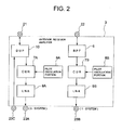
- FIG. 2 is a diagram showing the configuration of an example of the outdoor receiver amplifier 3.
- the outdoor receiver amplifier 3 is constituted by a duplexer 10 (hereinafter referred to as DUP 10) which separates a transmitted wireless signal from the wireless base station apparatus 5 within a band by eliminating useless energy outside the band for outputting to the transmitting/receiving antenna 1, and separates a received wireless signal from the transmitting/receiving antenna 1 within a band by eliminating useless energy outside the band, a pilot signal oscillation portion 8A forming a signal source for detection of a malfunction of the outdoor receiver amplifier 3, a circulator portion 7A (hereinafter referred to as CUR 7A) which outputs in a predetermined direction the received wireless signal and a pilot signal from the pilot signal oscillation portion 8A, and a low-noise amplification portion 9 (hereinafter referred to as LNA 9A) to which power from the feeder 4A is input and which performs low-nois
- LNA 9A low-noise amplification portion 9
- a path for a received wireless signal from the receiving-only antenna 2 is formed by a band-pass filter 6 (hereinafter referred to as BPF 6) which separates the received wireless signal within a band by eliminating useless energy outside the band, a CUR 7B, a pilot oscillation portion 8B, and an LNA 9B.
- BPF 6 band-pass filter 6
- a terminal 21 is a connection terminal of the transmitting/receiving antenna 1; a terminal 22 is a connection terminal of the receiving-only antenna 2; a terminal 23C is a transmitted signal input terminal; a terminal 23A is a 0-system received signal output terminal; and a terminal 23B is a 1-system received signal output terminal.
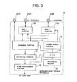
- FIG. 3 is a diagram showing the configuration of an example of the wireless base station apparatus 5.
- the wireless base station apparatus 5 is constituted by a wireless portion 11 which generates a wireless signal to be transmitted and demodulates received wireless signals in two systems, i.e., a 0-system and a 1-system, a power supply portion 14 which generates power to be supplied to the outdoor receiver amplifier 3, and bias T portions 15A and 15B which separate or multiplex received wireless signals and power, which supply the received wireless signals from the outdoor receiver amplifier 3 to the wireless portion 11 in a superposition manner, and which supply power from the power supply portion 14 to the receiving feeders 4A and 4B in a superposition manner.
- the wireless base station apparatus 5 is also constituted by a detection portion 12 which detects and determines signals demodulated by the wireless portion 11, i.e., the signals from the pilot oscillation portions 8A and 8B of the outdoor receiver amplifier 3, an RTWP processing portion 13 which performs RTWP processing by computing an NF of the outdoor receiver amplifier 3 from a report value from the detection portion 12, a central processing unit (CPU) 31 described below, and a recording medium 32.
- a detection portion 12 which detects and determines signals demodulated by the wireless portion 11, i.e., the signals from the pilot oscillation portions 8A and 8B of the outdoor receiver amplifier 3
- an RTWP processing portion 13 which performs RTWP processing by computing an NF of the outdoor receiver amplifier 3 from a report value from the detection portion 12, a central processing unit (CPU) 31 described below, and a recording medium 32.
- CPU central processing unit
- the first embodiment is an application of the present invention to a mobile communication system using as an access method a direct sequence-CDMA (DS-CDMA) having a chip rate of 3.84 Mbps.
- DS-CDMA direct sequence-CDMA
- FIG. 4 is a flowchart showing the operation of the first embodiment
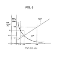
- FIG. 5 is diagram showing an input level-vs.-BER/RSCP characteristic of the wireless portion 11
- FIG. 6 is a diagram showing an input level-vs.-RTWP characteristic of the wireless portion 11
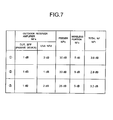
- FIG. 7 is a diagram of the NF level in the wireless base station system
- FIG. 8 is a diagram showing NF/RTWP characteristics of the wireless base station system.
- the operation of the first embodiment will be described with reference to FIGS. 1 to 8.
- the outdoor receiver amplifier 3 and the wireless base station apparatus 5 of the present invention are assumed to have a diversity function on the receiving side only.
- the flow of transmitted wireless signal in the transmitting system will first be described.
- the wireless portion 11 of the wireless base station apparatus 5 generates and outputs a predetermined modulated WCDMA wave for communication with a mobile device.
- the output transmitted wireless signal is supplied to the outdoor receiver amplifier 3 via the transmitting system feeder 4C, band-restricted by the DUP 10 in the outdoor receiver amplifier 3, and supplied to the transmitting/receiving antenna 1.
- a 0-system received wireless signal is received by the transmitting/receiving antenna 1, receiving-band-restricted by the DUP 10, supplied to the LNA 9A via the CUR 7A, power-amplified to a predetermined degree of amplification by the LNA 9A, and output from the outdoor receiver amplifier 3.
- the 0-system received wireless signal output from the receiver amplifier 3 is input to the wireless base station apparatus 5 via the 0-system receiving feeder 4A, supplied to the wireless portion 11 through the bias T portion 15A, and demodulated by CDMA despreading in the wireless portion 11.
- a 1-system received wireless signal is received by the receiving-only antenna 2, receiving-band-restricted by the BPF 6, supplied to the LNA 9B via the CUR 7B, power-amplified to a predetermined degree of amplification by the low-noise amplifier 9B, and output from the outdoor receiver amplifier 3.
- the 1-system received wireless signal output from the receiver amplifier 3 is input to the wireless base station apparatus 5 through the 1-system receiving feeder 4B, supplied to the wireless portion 11 through the bias T portion 15B, and demodulated by CDMA despreading in the wireless portion 11.
- a predetermined voltage is generated by the power supply portion 14 of the wireless base station apparatus 5.
- the bias T portions 15A and 15B superimpose this voltage on the signals transmitted through the feeders 4A and 4B. Power supplied via each of the feeders 4A and 4B is separated from the superimposed signals in the LNA 9A or 9B.
- the LNAs 9A and 9B perform predetermined low-noise amplification.
- the DS-WCDMA system is thus constructed which uses the wireless base station system constituted by the wireless base station apparatus 5, the outdoor receiver amplifier 3, the transmitting/receiving antenna 1 and the receiving-only antenna 2 and having the above-described signal flows, thereby enabling communication between mobile terminals.
- the outdoor receiver amplifier 3 is ordinarily placed in such an environment that its maintainability is low, i.e., at a position immediately below the outside antenna.
- a WCDMA wave is generated at a predetermined level in a predetermined code in the pilot oscillation portion 8A to be output as a pilot signal.
- This pilot signal is transmitted to the wireless portion 11 via the CUR 7A, the low-noise amplifier 9A, the feeder 4A, and the bias T portion 15A of the wireless base station apparatus 5 and is despread at a predetermined spreading gain by the wireless portion 11.
- Fault detection is performed in the detection portion 12 by determining whether this despread signal is within a predetermined received signal code power (RSCP) range and within a predetermined bit error rate (BER) range.
- RSCP received signal code power
- BER bit error rate
- an NF value is computed from the RSCP value and the BER value.
- the wireless portion 11 computes the BER value (on a curve similar to a hyperbolic curve) corresponding to the input level and the RSCP value linearly proportional to the input level, as shown in FIG. 5. That is, the wireless portion 11 has the function of computing the RSCP value and the BER value corresponding to the input level from the input level.
- the NF value of the equipment is obtained by an inverse operation from the BER value in particular, and a received input level value (RTWP value) determined by the RTWP processing portion 13 so as to include a value relating to the NF value is reported to a host unit.
- a WCDMA wave generated in the pilot oscillation portion 8B is transmitted to the wireless portion 11 via the CUR 7B, the low-noise amplifier 9B, the feeder 4B, and the bias T portion 15B of the wireless base station apparatus 5 and is despread at a predetermined spreading gain by the wireless portion 11.
- the despread signal undergoes the same processing in the detection portion 12.
- a standard sensitivity of the wireless base station system is prescribed in the specification (TS25.104) provided by the 3rd Generation Partnership Project Working Group 4 (3GPP WG4) such that the input level when the data rate is 12.2 kbps and when the BER is 0.1% is -121 dBm or less.
- Standard sensitivity [dBm] -174 [dBm/Hz] + 10*log(12.2k) [dBHz] + Eb/No + NF + Margin where Eb/No is 5.09 dB, NF value is 5 dB, and Margin is 2 dB.
- RTWP value an agreement was also reached on adding a value relating to the NF and thermal noise of the equipment to the total power received through antenna input terminal.
- NFt 10log(10 ⁇ (NFa/10) + ((10 ⁇ ((NFb/10 + NFc/10)/10) - 1)/10 ⁇ (Ga/10)))
- the standard sensitivity is determined from NFa and gain Ga of the outdoor receiver amplifier 3, feeder loss NFb, and NFc of the wireless portion 11.
- NFa of the outdoor receiver amplifier 3 is determined from the losses in the DUP 10 and the BPF 6, which are passive devices, (the losses in the CURs 7A and 7B ignored) and NFd of the LNAs 9A and 9B.
- the desired value of NFt of the outdoor receiver amplifier 3, e.g., 3 dB can be obtained if the loss due to the DUP 10 and the BPF 6 is 1 dB and if NFd of the LNAs 9A and 9B is 2 dB.
- the total NF from the pilot oscillation portion 8A or 8B is influenced by the NF after the CUR 7A or 7B.
- the loss from each of the pilot oscillation portions 8A and 8B of CURs 7A and 7B to the LNA 9A or 9B is 1 dB, equal to that in the case of the DUP 10.
- the total NFt of the wireless base station system is equal to the total NFe from the pilot portion 8A or 8B.
- the RSCP value and the BER value obtained when a -121 dBm WCDMA signal is input to one of the antenna input terminals and the RSCP value and the BER value obtained when the -121 dBm WCDMA signal is output from the pilot portion 8A or 8B can be computed as the same values.
- a method computing the RTWP value is defined as described below.
- a value relating to the NF and thermal noise of the equipment is added to the total power received through each of the antenna input terminals, i.e., the transmitting/receiving antenna 1 and the receiving-only antenna 2.
- the total power is the entire WCDMA energy input to the antenna. That is, if a plurality of mobile terminals exist, the total power is the sum of the value of power totalized from the mobile terminals and the level of thermal noise.
- the NF of the equipment is the NFt from the antenna terminal, i.e., the total NF of the wireless base station system.
- processing in the RTWP processing portion 13 of the wireless base station apparatus 5 should be performed so that the RTWP report value is -102.8/-101.7/-100.6/-98.7/-89.8 dBm (see FIGS. 8 and 6).
- RTWP detection method in accordance with the present invention will next be described below with reference to FIG. 4.
- the above-described gain, NF, and loss values are used with respect to the outdoor receiver amplifier 3, the feeders 4A and 4B, and the wireless portion 11.
- the RTWP value detection process be executed before the WCDMA system becomes operational, and that, after the system has started operating, the RTWP value detection process be executed periodically or in a situation where variation in a natural environment, e.g., variation in open-air temperature is small and traffic is low.
- the voltage is applied to the LNAs 4A and 4B and to the pilot oscillation portions 8A and 8B (S2) and the pilot oscillation portions 8A and 8B output WCDMA signals in a predetermined code at a transmission rate of 12.2 kbps and at -121 dBm.
- the RSCP value is computed from the despread signals (RSCP value assumed to be XdBm).
- the parameters for computation of the RSCP value are uniquely determined from the wireless level diagram (the characteristic diagram of FIG. 5).
- a second embodiment of the present invention will next be described.
- An example of the operation in a case where a decrease in open-air temperature, for example, occurs as a change in a natural environment generally, the NF of the active element is thereby reduced; for example, the NF of the LNAs 9A and 9B is reduced from 2 dB to 1 dB (see 2 in FIG. 7) will be described in detail.
- the -121 dBm WCDMA signal from the pilot oscillation portions 8A and 8B the wireless level diagram is not changed from that initially set. Therefore the RSCP value (XdBm) is computed also from -121 dBm.
- the value 2.8 dB is stored as NFt of the RTWP processing portion 13. If the input level is -108/-105/-103/-100/-90 dBm, the RTWP value corresponding to the input level is -103.4/-102.1/-101/-98.9/-89.8 dBm (see 2 in FIG. 8 and FIG. 6).
- the correct RTWP value at the current time can be computed by the process of this embodiment shown in the flowchart.
- a third embodiment of the present invention will be described. Even in a case where a wireless base station system is constructed, for example, with such a feeder length that the feeder loss is 25 dB, the following computation can be performed if the basic form of the wireless level diagram is provided.
- a fixed amplification degree of 40 dB for an out door air receiver amplifier (OARA), a feeder loss of ⁇ dB, and an RSCP value of -81 dBm after despreading in the wireless portion 11 are computed from the pilot output level -121 dBm.
- OARA out door air receiver amplifier
- a feeder loss of ⁇ dB a feeder loss of ⁇ dB
- an RSCP value of -81 dBm after despreading in the wireless portion 11 are computed from the pilot output level -121 dBm.
- the value 25 dB smaller by 5 dB than the feeder loss reference value 30 dB can be computed.
- an equipment NFt value of 3.2 dB
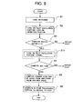
- FIG. 9 is a flowchart showing an operation of the fourth embodiment.
- the flowchart of FIG. 9 is formed by adding a step S11 between steps S3 and S4 shown in the flowchart of FIG. 4, and steps S1 to S6 shown in the flowchart of FIG. 9 are the same as those in FIG. 4. Therefore the description of these steps will not be repeated.
- a fixed value of -121 dBm is used as the output level of the above-described pilot oscillation portions 8A and 8B even for computation of the RSCP value and the BER value.
- the output level of the pilot oscillation portions 8A and 8B is increased, for example, by 20 dB in advance to ensure detection of the RSCP value in a situation where RTWP processing may be influenced by an external factor, e.g., high traffic.
- the output level is thereafter returned to -121 dBm (step S11) and the BER value is computed.
- the fifth embodiment relates to a recording medium on which a program for making a computer carry out the method of monitoring the receiving portion in the wireless base station system is stored.
- the wireless base station apparatus 5 shown in FIG. 3 includes the CPU 31 and the recording medium 32.
- a program for making the computer execute the process shown in the flowchart of FIG. 4 or 9 is recorded on the recording medium 32.
- the CPU 31 reads out the program from the recording medium 32 and controls the power supply portion 14, the wireless portion 11, the detection portion 12, and the RTWP processing portion 13 in accordance with the program.
- the contents of the program have already been described and the description of them will be omitted.
- a receiving portion monitoring system in a wireless base station system includes receiving and amplifying means for amplifying a received signal, and wireless base station means for detecting a fault in the receiving and amplifying means on the basis of a demodulated signal obtained by demodulating a signal output from the receiving and amplifying means;
- the receiving and amplifying means includes a pilot signal generation portion which generates a pilot signal for detection of a fault, and an amplifier which amplifies the received signal and the pilot signal;
- the wireless base station means includes a wireless portion which demodulates a signal output from the amplifier and computes an RSCP value and a BER value from the demodulated signal, a detection portion which computes a feeder loss and an NF value between the receiving and amplifying means and the wireless base station means from the computed RSCP and BER values, and an RTWP processing portion which outputs an RTWP value including a value relating to the NF value detected by the detection portion.
- a first advantage of the present invention resides in that the feeder loss can be automatically computed. This is because the RSCP value can be computed by despreading in the wireless portion a predetermined WCDMA signal from the pilot oscillation portion.
- a second advantage of the present invention resides in that the NF of the outdoor receiver amplifier can be automatically computed. This is because the BER value can be computed by despreading in the wireless portion a predetermined WCDMA signal from the pilot oscillation portion.
- a third advantage of the present invention resides in that the maintainability of the outdoor receiver amplifier is improved, there is no need to move measuring devices to measurement places, and there is no need to perform operations in any dangerous place, e.g., immediately below the outside antenna. This is because the NF of the outdoor receiver amplifier and the loss in the feeder can be computed by despreading in the wireless portion a predetermined WCDMA signal from the pilot oscillation portion.
- a fourth advantage of the present invention resides in that variation in the NF of the outdoor receiver amplifier due to variation in a natural environment can be detected. This is because the BER can be computed by despreading in the wireless portion a predetermined WCDMA signal from the pilot oscillation portion.
- a fifth advantage of the present invention resides in that the RTWP can be computed with accuracy even in the case of a multivendor configuration of the outdoor receiver amplifier. This is because the NF of the outdoor receiver amplifier can be computed and because the initial value of the equation for computation in the RTWP processing portion can be changed.
Landscapes
- Engineering & Computer Science (AREA)
- Physics & Mathematics (AREA)
- Electromagnetism (AREA)
- Computer Networks & Wireless Communication (AREA)
- Signal Processing (AREA)
- Quality & Reliability (AREA)
- Monitoring And Testing Of Transmission In General (AREA)
- Mobile Radio Communication Systems (AREA)
Abstract
A noise figure (NF) of an outdoor receiver amplifier and a loss in a feeder are automatically computed to report a correct level of received total wideband power (RTWP). A received signal code power (RSCP) value and a bit error rate (BER) value are computed by demodulating in a wireless portion of a wireless base station system a pilot signal generated in the outdoor receiver amplifier, and the feeder loss and the NF value are computed in a detection portion from the RSCP value and the BER value. Further, a received total wideband power value (RTWP value) including a value relating to the NF value is reported to a host unit by an RTWP processing portion.
Description
- The present invention relates to a system and method for monitoring a receiving portion in a wireless base station system and to a recording medium on which a monitoring program is recorded. More particularly, the present invention relates to a system and method for monitoring a receiving portion in a wireless base station system which performs communication with mobile terminals and to a recording medium on which a monitoring program is recorded.
- In wireless base station systems, measurements relating to a wireless level diagram are made. In particular, when a noise figure (NF), gain, and feeder loss of an outdoor receiver amplifier are actually measured, there is a need to move measuring devices to the measurement places. On the other hand, desktop measurements are made in such a manner that a feeder loss is obtained from a feeder length and a determination is made by a theoretical process as to whether the total NF is appropriate in terms of wideband code division multiple access (WCDMA) system, and the determination result is verified with the above-mentioned actual device. A difference between NF characteristics which occurs in a case where the out door receiver amplifier is configured for a multivendor service is multiplied by an offset according to station data or the like to form a WCDMA system parameter.
- However, with the process including moving measuring devices to measurement places, there is a disadvantage that it is necessary to perform operations in dangerous places, e.g., a place immediately below an antenna in the case of measurement of an outdoor receiver amplifier. There is also a disadvantage that troublesome operations for computing feeder loss, a total NF, etc., are required.
- Systems for the above-described kind of receiving portion monitoring are disclosed in Japanese Patent Laid-Open No. 9-200069 (hereinafter referred to as related art document 1) and No. 11-186956 (hereinafter referred to as related art document 2) and Japanese Patent Publication No. 2503889 (hereinafter referred to as related art document 3).
- The technique disclosed in the
related art document 1 relates to a device for detecting a fault in a high-sensitivity wireless portion installed outside a building. A detection of a fault in an outdoor receiver is performed by making determination using monitoring means 35 as to whether a pilot signal level is lower than a reference value. The invention disclosed in this document, however, differs from the present invention in that it does not use the bit error rate (BER) as a determination criterion. - The technique disclosed in the
related art document 2 uses means for detecting a fading pitch from a reception signal, BER detection means, received input level measuring means in a mobile wireless portion, and appropriate moving speed detection means for deriving a current appropriate moving speed from fading pitch detection information, BER, and received input level information. This technique enables a user to reduce a deterioration in communication quality due to fading by considering the derived moving speed. However, the invention disclosed in this document differs from the present invention in that it is concerned with a mobile wireless portion and aims to reduce deterioration in communication quality due to fading. - The technique disclosed in the
related art document 3 relates to a device for detecting a fault in a receiver amplifier installed outside a building and makes fault determination by preparing a fault detection reference value from a standard attenuation value relating to leakage of a transmitted signal from a transmitter to a receiving circuit in an antenna-sharing unit, a standard amplification value of the receiver amplifier, and transmission power information of the transmitter, and by comparing electric field intensity information output from an electric field detecting portion with the reference value. The invention disclosed in this document differs from the present invention in that it uses no pilot signal. - An object of the present invention is to provide, as means capable of solving the above-described problem, a system and method for monitoring a receiving portion in a wireless base station system in which the NF and feeder loss of an outdoor receiver amplifier are automatically computed to report a correct level of received total wideband power (RTWP).
- To attain the above-described object, according to one aspect of the present invention, there is provided a receiving portion monitoring system in a wireless base station system including receiving and amplifying means for amplifying a received signal, and wireless base station means for demodulating a signal output from the receiving and amplifying means and for detecting a fault in the receiving and amplifying means on the basis of the demodulated signal, the receiving and amplifying means including a pilot signal generation portion which generates a pilot signal for detection of a fault, and an amplifier which amplifies the received signal and the pilot signal, and the wireless base station means including a wireless portion which demodulates a signal output from the amplifier and computes a received signal code power (RSCP) value and a BER value from the demodulated signal, a detection portion which computes a feeder loss and an NF value between the receiving and amplifying means and the wireless base station means from the computed RSCP and BER values, and an RTWP processing portion which outputs an RTWP value including a value relating to the NF value detected by the detection portion.
- According to another aspect of the present invention, there is provided a receiving portion monitoring method for a wireless base station system including receiving and amplifying means for amplifying a received signal, and wireless base station means for demodulating a signal output from the receiving and amplifying means and for detecting a fault in the receiving and amplifying means on the basis of the demodulated signal, the receiving and amplifying means including a pilot signal generation portion which generates a pilot signal for detection of a fault, and an amplifier which amplifies the received signal and the pilot signal, the method comprising, as steps to be performed in the wireless base station means, a first step of demodulating a signal output from the amplifier and computing an RSCP value and a BER value from the demodulated signal, a second step of computing a feeder loss and an NF value between the receiving and amplifying means and the wireless base station means from the computed RSCP and BER values, and a third step of outputting an RTWP value including a value relating to the NF value detected in the second step.
- According to still another aspect of the present invention, there is provided a recording medium on which is recorded a program for making a computer carry out a receiving portion monitoring method for a wireless base station system including receiving and amplifying means for amplifying a received signal, and wireless base station means for demodulating a signal output from the receiving and amplifying means and for detecting a fault in the receiving and amplifying means on the basis of the demodulated signal, the receiving and amplifying means including a pilot signal generation portion which generates a pilot signal for detection of a fault, and an amplifier which amplifies the received signal and the pilot signal, the wireless base station means including the recording medium, the program including a first step of demodulating a signal output from the amplifier and computing an RSCP value and a BER value from the demodulated signal, a second step of computing a feeder loss and an NF value between the receiving and amplifying means and the wireless base station means from the computed RSCP and BER values, and a third step of outputting an RTWP value including a value relating to the NF value detected in the second step.
- According to the present invention, the system is arranged to automatically compute the NF of the outdoor receiver amplifier and the loss in the feeder and to report correct RTWP, thus solving the above-described problem.
-
- FIG. 1 is a diagram showing a configuration of a wireless base station system in the best mode of implementation of the present invention;
- FIG. 2 is a diagram showing a configuration of an example of an
outdoor receiver amplifier 3; - FIG. 3 is a diagram showing a configuration of an example of a wireless
base station apparatus 5; - FIG. 4 is a flowchart showing an operation of a first embodiment of the invention;
- FIG. 5 is a diagram showing an input level-vs.-BER/RSCP characteristic of a
wireless portion 11; - FIG. 6 is a diagram showing an input level-vs.-RTWP characteristic of the
wireless portion 11; - FIG. 7 is a diagram of the NF level in the wireless base station system;
- FIG. 8 is a diagram showing NF/RTWP characteristics of the wireless base station system; and
- FIG. 9 is a flowchart showing an operation of a fourth embodiment.
- Embodiments of the present invention will be described with reference to the accompanying drawings. FIG. 1 is a diagram showing the configuration of a wireless base station system in the best mode of implementation of the invention. Referring to FIG. 1, the wireless base station system is constituted by a transmitting/receiving
antenna 1, a receiving-only antenna 2, anoutdoor receiver amplifier 3 which separates a transmitted wireless signal and a received wireless signal from each other and performs low-nose amplification of the received wireless signal only, a wirelessbase station apparatus 5 which performs modulation/demodulation of transmitted/received wireless signals and detects a malfunction of theoutdoor receiver amplifier 3,feeders outdoor receiver amplifier 3 and the wirelessbase station apparatus 5 and used for superimposition of transmitted/received wireless signals and power supplied to theoutdoor receiver amplifier 3, and afeeder 4C used for transmitted wireless signal transmission. - The configuration of the
outdoor receiver amplifier 3 will next be described. FIG. 2 is a diagram showing the configuration of an example of theoutdoor receiver amplifier 3. Referring to FIG. 2, theoutdoor receiver amplifier 3 is constituted by a duplexer 10 (hereinafter referred to as DUP 10) which separates a transmitted wireless signal from the wirelessbase station apparatus 5 within a band by eliminating useless energy outside the band for outputting to the transmitting/receivingantenna 1, and separates a received wireless signal from the transmitting/receivingantenna 1 within a band by eliminating useless energy outside the band, a pilotsignal oscillation portion 8A forming a signal source for detection of a malfunction of theoutdoor receiver amplifier 3, acirculator portion 7A (hereinafter referred to asCUR 7A) which outputs in a predetermined direction the received wireless signal and a pilot signal from the pilotsignal oscillation portion 8A, and a low-noise amplification portion 9 (hereinafter referred to asLNA 9A) to which power from thefeeder 4A is input and which performs low-noise amplification of the received wireless signal. - Similarly to the path from the transmitting/receiving
antenna 1, a path for a received wireless signal from the receiving-only antenna 2 is formed by a band-pass filter 6 (hereinafter referred to as BPF 6) which separates the received wireless signal within a band by eliminating useless energy outside the band, aCUR 7B, apilot oscillation portion 8B, and anLNA 9B. - A
terminal 21 is a connection terminal of the transmitting/receivingantenna 1; aterminal 22 is a connection terminal of the receiving-only antenna 2; aterminal 23C is a transmitted signal input terminal; aterminal 23A is a 0-system received signal output terminal; and aterminal 23B is a 1-system received signal output terminal. - The configuration of the wireless
base station apparatus 5 will next be described. FIG. 3 is a diagram showing the configuration of an example of the wirelessbase station apparatus 5. Referring to FIG. 3, the wirelessbase station apparatus 5 is constituted by awireless portion 11 which generates a wireless signal to be transmitted and demodulates received wireless signals in two systems, i.e., a 0-system and a 1-system, apower supply portion 14 which generates power to be supplied to theoutdoor receiver amplifier 3, andbias T portions outdoor receiver amplifier 3 to thewireless portion 11 in a superposition manner, and which supply power from thepower supply portion 14 to thereceiving feeders base station apparatus 5 is also constituted by adetection portion 12 which detects and determines signals demodulated by thewireless portion 11, i.e., the signals from thepilot oscillation portions outdoor receiver amplifier 3, anRTWP processing portion 13 which performs RTWP processing by computing an NF of theoutdoor receiver amplifier 3 from a report value from thedetection portion 12, a central processing unit (CPU) 31 described below, and arecording medium 32. - Embodiments of the present invention will be described below as examples of the operation in the mode of implementation of the present invention by using concrete numeric values. Now, a first embodiment will be described. The first embodiment is an application of the present invention to a mobile communication system using as an access method a direct sequence-CDMA (DS-CDMA) having a chip rate of 3.84 Mbps.
- FIG. 4 is a flowchart showing the operation of the first embodiment; FIG. 5 is diagram showing an input level-vs.-BER/RSCP characteristic of the
wireless portion 11; FIG. 6 is a diagram showing an input level-vs.-RTWP characteristic of thewireless portion 11; FIG. 7 is a diagram of the NF level in the wireless base station system; and FIG. 8 is a diagram showing NF/RTWP characteristics of the wireless base station system. The operation of the first embodiment will be described with reference to FIGS. 1 to 8. Theoutdoor receiver amplifier 3 and the wirelessbase station apparatus 5 of the present invention are assumed to have a diversity function on the receiving side only. - The flow of transmitted wireless signal in the transmitting system will first be described. The
wireless portion 11 of the wirelessbase station apparatus 5 generates and outputs a predetermined modulated WCDMA wave for communication with a mobile device. The output transmitted wireless signal is supplied to theoutdoor receiver amplifier 3 via the transmittingsystem feeder 4C, band-restricted by theDUP 10 in theoutdoor receiver amplifier 3, and supplied to the transmitting/receivingantenna 1. - The flows of received wireless signals in the receiving system are as described below. A 0-system received wireless signal is received by the transmitting/receiving
antenna 1, receiving-band-restricted by theDUP 10, supplied to the LNA 9A via theCUR 7A, power-amplified to a predetermined degree of amplification by the LNA 9A, and output from theoutdoor receiver amplifier 3. - The 0-system received wireless signal output from the
receiver amplifier 3 is input to the wirelessbase station apparatus 5 via the 0-system receiving feeder 4A, supplied to thewireless portion 11 through thebias T portion 15A, and demodulated by CDMA despreading in thewireless portion 11. - Similarly, in the 1-system, a 1-system received wireless signal is received by the receiving-
only antenna 2, receiving-band-restricted by theBPF 6, supplied to the LNA 9B via theCUR 7B, power-amplified to a predetermined degree of amplification by the low-noise amplifier 9B, and output from theoutdoor receiver amplifier 3. - The 1-system received wireless signal output from the
receiver amplifier 3 is input to the wirelessbase station apparatus 5 through the 1-system receiving feeder 4B, supplied to thewireless portion 11 through thebias T portion 15B, and demodulated by CDMA despreading in thewireless portion 11. - Supply of power to the
outdoor receiver amplifier 3 will be described. First, a predetermined voltage is generated by thepower supply portion 14 of the wirelessbase station apparatus 5. Thebias T portions feeders 4A and 4B. Power supplied via each of thefeeders LNA LNAs - The DS-WCDMA system is thus constructed which uses the wireless base station system constituted by the wireless
base station apparatus 5, theoutdoor receiver amplifier 3, the transmitting/receivingantenna 1 and the receiving-only antenna 2 and having the above-described signal flows, thereby enabling communication between mobile terminals. - The
outdoor receiver amplifier 3 is ordinarily placed in such an environment that its maintainability is low, i.e., at a position immediately below the outside antenna. - The flows of signals for detection of a fault in the
outdoor receiver amplifier 3 will be described. First, in the 0-system receiving line, a WCDMA wave is generated at a predetermined level in a predetermined code in thepilot oscillation portion 8A to be output as a pilot signal. This pilot signal is transmitted to thewireless portion 11 via theCUR 7A, the low-noise amplifier 9A, thefeeder 4A, and thebias T portion 15A of the wirelessbase station apparatus 5 and is despread at a predetermined spreading gain by thewireless portion 11. Fault detection is performed in thedetection portion 12 by determining whether this despread signal is within a predetermined received signal code power (RSCP) range and within a predetermined bit error rate (BER) range. Also, an NF value is computed from the RSCP value and the BER value. - The
wireless portion 11 computes the BER value (on a curve similar to a hyperbolic curve) corresponding to the input level and the RSCP value linearly proportional to the input level, as shown in FIG. 5. That is, thewireless portion 11 has the function of computing the RSCP value and the BER value corresponding to the input level from the input level. The NF value of the equipment is obtained by an inverse operation from the BER value in particular, and a received input level value (RTWP value) determined by theRTWP processing portion 13 so as to include a value relating to the NF value is reported to a host unit. - Similarly, in the 1-system receiving line, a WCDMA wave generated in the
pilot oscillation portion 8B is transmitted to thewireless portion 11 via theCUR 7B, the low-noise amplifier 9B, thefeeder 4B, and thebias T portion 15B of the wirelessbase station apparatus 5 and is despread at a predetermined spreading gain by thewireless portion 11. The despread signal undergoes the same processing in thedetection portion 12. - A standard sensitivity of the wireless base station system is prescribed in the specification (TS25.104) provided by the 3rd Generation Partnership Project Working Group 4 (3GPP WG4) such that the input level when the data rate is 12.2 kbps and when the BER is 0.1% is -121 dBm or less.
- The following is a basis for setting this value, on which an agreement was reached:

- In WCDMA wireless system design, therefore, there is a need to set the total NFt from the antenna end equal to or smaller than 5 dB ("Margin" ignored). A concrete example of the total NFt setting is shown below in detail with respect to a case where the gain Ga of the
outdoor receiver amplifier 3 is 40 dB, the NFa value of theoutdoor receiver amplifier 3 is 3 dB, the feeder loss NFb is 30 dB, and the NFc value of thewireless portion 11 is 5 dB. - The total NFt of the wireless base station system is first obtained.

- From this equation, a total NFt value of 3.6 dB is obtained (see ① in FIG. 7). Thus, a wireless level diagram satisfying the standard sensitivity requirement can be obtained.
- As described above in detail, the standard sensitivity is determined from NFa and gain Ga of the
outdoor receiver amplifier 3, feeder loss NFb, and NFc of thewireless portion 11. NFa of theoutdoor receiver amplifier 3 is determined from the losses in theDUP 10 and theBPF 6, which are passive devices, (the losses in theCURs LNAs - For example, the desired value of NFt of the
outdoor receiver amplifier 3, e.g., 3 dB can be obtained if the loss due to theDUP 10 and theBPF 6 is 1 dB and if NFd of theLNAs LNAs - With respect to the WCDMA signal generated by the
pilot oscillation portion pilot oscillation portion CUR pilot oscillation portions CURs LNA DUP 10. Thus, the total NFt of the wireless base station system is equal to the total NFe from thepilot portion - More specifically, the RSCP value and the BER value obtained when a -121 dBm WCDMA signal is input to one of the antenna input terminals and the RSCP value and the BER value obtained when the -121 dBm WCDMA signal is output from the
pilot portion - A method computing the RTWP value is defined as described below. A value relating to the NF and thermal noise of the equipment is added to the total power received through each of the antenna input terminals, i.e., the transmitting/receiving
antenna 1 and the receiving-only antenna 2. The total power is the entire WCDMA energy input to the antenna. That is, if a plurality of mobile terminals exist, the total power is the sum of the value of power totalized from the mobile terminals and the level of thermal noise. The NF of the equipment is the NFt from the antenna terminal, i.e., the total NF of the wireless base station system. - More specifically, if the level of an input to the transmitting/receiving
antenna 1 or the receiving-only antenna 2 is A (dBm); the thermal noise level is B (dBm) = -108 (dBm/3.84 MHz); and the equipment NF is NFt (dB), the value (RTWP) measured through the equipment is as expressed by
- Then, if NFt is 3.6 dB and if the input level is -108/-105/-103/-100/-90 dBm, processing in the
RTWP processing portion 13 of the wirelessbase station apparatus 5 should be performed so that the RTWP report value is -102.8/-101.7/-100.6/-98.7/-89.8 dBm (see FIGS. 8 and 6). - An RTWP detection method in accordance with the present invention will next be described below with reference to FIG. 4. The above-described gain, NF, and loss values are used with respect to the
outdoor receiver amplifier 3, thefeeders wireless portion 11. Generally speaking, it is preferred that the RTWP value detection process be executed before the WCDMA system becomes operational, and that, after the system has started operating, the RTWP value detection process be executed periodically or in a situation where variation in a natural environment, e.g., variation in open-air temperature is small and traffic is low. - When the
power supply portion 14 is turned on (S1), the voltage is applied to theLNAs pilot oscillation portions pilot oscillation portions wireless portion 11. The RSCP value is computed from the despread signals (RSCP value assumed to be XdBm). The parameters for computation of the RSCP value are uniquely determined from the wireless level diagram (the characteristic diagram of FIG. 5). - From the output power from the
pilot oscillation portion outdoor receiver amplifier 3, the loss in thefeeder 
- Subsequently, the BER is computed (BER assumed to be Y%) (S4). If, for example, Y = 0.1% is thereby obtained (see FIG. 5), Y does not exceed B=o.2% (that is, Y ≦ B), it is determined that the system has no BER fault (that is, it is operating normally).
- Subsequently, the feeder loss of 30 dB is computed by inverse operation from the RSCP value and the BER value obtained this time. Total NFt = 3.6 dB is thereby obtained (S5). The NFt value of the equation (3) computed by the
RTWP processing portion 13 is initialized to 3.6 dB according to this obtained NFt, thus completing the process (S6). - A second embodiment of the present invention will next be described. An example of the operation in a case where a decrease in open-air temperature, for example, occurs as a change in a natural environment (generally, the NF of the active element is thereby reduced; for example, the NF of the
LNAs pilot oscillation portions - The value 2.8 dB is stored as NFt of the
RTWP processing portion 13. If the input level is -108/-105/-103/-100/-90 dBm, the RTWP value corresponding to the input level is -103.4/-102.1/-101/-98.9/-89.8 dBm (see ② in FIG. 8 and FIG. 6). - Thus, even when the NF of an out door receiver amplifier is changed due to a change in natural environment, the correct RTWP value at the current time can be computed by the process of this embodiment shown in the flowchart.
- A third embodiment of the present invention will be described. Even in a case where a wireless base station system is constructed, for example, with such a feeder length that the feeder loss is 25 dB, the following computation can be performed if the basic form of the wireless level diagram is provided. A fixed amplification degree of 40 dB for an out door air receiver amplifier (OARA), a feeder loss of α dB, and an RSCP value of -81 dBm after despreading in the
wireless portion 11 are computed from the pilot output level -121 dBm. Thus, thevalue 25 dB smaller by 5 dB than the feederloss reference value 30 dB can be computed. Next, an equipment NFt value of 3.2 dB can be computed by inverse operation from the corresponding BER value 0.01% and thevalue 25 dB (see ③ in FIG. 7). - A fourth embodiment of the present invention will be described. FIG. 9 is a flowchart showing an operation of the fourth embodiment. The flowchart of FIG. 9 is formed by adding a step S11 between steps S3 and S4 shown in the flowchart of FIG. 4, and steps S1 to S6 shown in the flowchart of FIG. 9 are the same as those in FIG. 4. Therefore the description of these steps will not be repeated.
- In the above-described embodiments, a fixed value of -121 dBm is used as the output level of the above-described
pilot oscillation portions pilot oscillation portions - A fifth embodiment of the present invention will be described. The fifth embodiment relates to a recording medium on which a program for making a computer carry out the method of monitoring the receiving portion in the wireless base station system is stored.
- The wireless
base station apparatus 5 shown in FIG. 3 includes theCPU 31 and therecording medium 32. A program for making the computer execute the process shown in the flowchart of FIG. 4 or 9 is recorded on therecording medium 32. TheCPU 31 reads out the program from therecording medium 32 and controls thepower supply portion 14, thewireless portion 11, thedetection portion 12, and theRTWP processing portion 13 in accordance with the program. The contents of the program have already been described and the description of them will be omitted. - According to the present invention, a receiving portion monitoring system in a wireless base station system includes receiving and amplifying means for amplifying a received signal, and wireless base station means for detecting a fault in the receiving and amplifying means on the basis of a demodulated signal obtained by demodulating a signal output from the receiving and amplifying means; the receiving and amplifying means includes a pilot signal generation portion which generates a pilot signal for detection of a fault, and an amplifier which amplifies the received signal and the pilot signal; and the wireless base station means includes a wireless portion which demodulates a signal output from the amplifier and computes an RSCP value and a BER value from the demodulated signal, a detection portion which computes a feeder loss and an NF value between the receiving and amplifying means and the wireless base station means from the computed RSCP and BER values, and an RTWP processing portion which outputs an RTWP value including a value relating to the NF value detected by the detection portion. The above-described problem can be solved by this system.
- More specifically, a first advantage of the present invention resides in that the feeder loss can be automatically computed. This is because the RSCP value can be computed by despreading in the wireless portion a predetermined WCDMA signal from the pilot oscillation portion.
- A second advantage of the present invention resides in that the NF of the outdoor receiver amplifier can be automatically computed. This is because the BER value can be computed by despreading in the wireless portion a predetermined WCDMA signal from the pilot oscillation portion.
- A third advantage of the present invention resides in that the maintainability of the outdoor receiver amplifier is improved, there is no need to move measuring devices to measurement places, and there is no need to perform operations in any dangerous place, e.g., immediately below the outside antenna. This is because the NF of the outdoor receiver amplifier and the loss in the feeder can be computed by despreading in the wireless portion a predetermined WCDMA signal from the pilot oscillation portion.
- A fourth advantage of the present invention resides in that variation in the NF of the outdoor receiver amplifier due to variation in a natural environment can be detected. This is because the BER can be computed by despreading in the wireless portion a predetermined WCDMA signal from the pilot oscillation portion.
- A fifth advantage of the present invention resides in that the RTWP can be computed with accuracy even in the case of a multivendor configuration of the outdoor receiver amplifier. This is because the NF of the outdoor receiver amplifier can be computed and because the initial value of the equation for computation in the RTWP processing portion can be changed.
Claims (23)
- A receiving portion monitoring system in a wireless base station system, comprising:receiving and amplifying means for amplifying a received signal; andwireless base station means for demodulating a signal output from said receiving and amplifying means and for detecting a fault in said receiving and amplifying means on the basis of the demodulated signal,wherein said receiving and amplifying means includes a pilot signal generation portion which generates a pilot signal for detection of a fault, and an amplifier which amplifies the received signal and the pilot signal, andsaid wireless base station means includes a wireless portion which demodulates a signal output from said amplifier and computes an RSCP value and a BER value from the demodulated signal, a detection portion which computes a feeder loss and an NF value between said receiving and amplifying means and said wireless base station means from the computed RSCP and BER values, and an RTWP processing portion which outputs an RTWP value including a value relating to the NF value detected by said detection portion.
- The receiving portion monitoring system according to claim 1, wherein said detection portion makes a determination as to whether each of the computed RSCP and BER values is within a predetermined range.
- The receiving portion monitoring system according to claim 1, wherein the loss in the path through which the received signal is input to said amplifier and the loss in the path which the pilot signal is input to said amplifier are equal to each other.
- The receiving portion monitoring system according to claim 1, wherein said wireless portion computes the RSCP value and the BER value by using the input level-vs.-RSCP value/BER value characteristic table.
- The receiving portion monitoring system according to claim 1, wherein said RSCP value is computed from the output power of the pilot signal, the gain of said amplifier, the feeder loss between said receiving and amplifying means and said wireless base station means, and the spreading gain of said wireless portion.
- The receiving portion monitoring system according to claim 1, wherein said NF value is computed from the NF value and the gain of said amplifier, the feeder loss between said receiving and amplifying means and said wireless base station means, and the NF value of said wireless portion.
- The receiving portion monitoring system according to claim 1, wherein said RTWP value is computed from the input level of the received signal, a thermal noise level, and the NF value.
- A receiving portion monitoring method for a wireless base station system including receiving and amplifying means for amplifying a received signal, and wireless base station means for demodulating a signal output from the receiving and amplifying means and for detecting a fault in the receiving and amplifying means on the basis of the demodulated signal,
wherein said receiving and amplifying means includes a pilot signal generation portion which generates a pilot signal for detection of a fault, and an amplifier which amplifies the received signal and the pilot signal, and
said wireless base station means comprises:a first step of demodulating a signal output from the amplifier and computing an RSCP value and a BER value from the demodulated signal;a second step of computing a feeder loss and an NF value between the receiving and amplifying means and the wireless base station means from the computed RSCP and BER values; anda third step of outputting an RTWP value including a value relating to the NF value detected in the second step. - The receiving portion monitoring method according to claim 8, wherein said second step comprises making a determination as to whether each of the computed RSCP and BER values is within a predetermined range.
- The receiving portion monitoring method according to claim 8, wherein the loss in the path through which the received signal is input to the amplifier and the loss in the path which the pilot signal is input to the amplifier are equal to each other.
- The receiving portion monitoring method according to claim 8, wherein in said first step said RSCP value and said BER value are computed by using the input level-vs.-RSCP value/BER value characteristic table.
- The receiving portion monitoring method according to claim 8, wherein said RSCP value is computed from the output power of the pilot signal, the gain of the amplifier, the feeder loss between the receiving and amplifying means and the wireless base station means, and the spreading gain of said first step.
- The receiving portion monitoring method according to claim 8, wherein said NF value is computed from the NF value and the gain of the amplifier, the feeder loss between the receiving and amplifying means and the wireless base station means, and the NF value of said first step.
- The receiving portion monitoring method according to claim 8, wherein said RTWP value is computed from the input level of the received signal, a thermal noise level, and the NF value.
- The receiving portion monitoring method according to claim 8, further comprising a step of increasing the level of the pilot signal by a predetermined value than a reference value in advance, and returning the level of the pilot signal to the reference value between computation of the RSCP value and computation of the BER value in said first step.
- A recording medium on which there is recorded a program for making a computer carry out a receiving portion monitoring method for a wireless base station system including receiving and amplifying means for amplifying a received signal, and wireless base station means for demodulating a signal output from the receiving and amplifying means and for detecting a fault in the receiving and amplifying means on the basis of the demodulated signal,
wherein said receiving and amplifying means includes a pilot signal generation portion which generates a pilot signal for detection of a fault, and an amplifier which amplifies the received signal and the pilot signal, the wireless base station means including the recording medium, and
said program includes:a first step of demodulating a signal output from the amplifier and computing an RSCP value and a BER value from the demodulated signal;a second step of computing a feeder loss and an NF value between the receiving and amplifying means and the wireless base station means from the computed RSCP and BER values; anda third step of outputting an RTWP value including a value relating to the NF value detected in the second step. - The recording medium according to claim 16, wherein said second step comprises making a determination as to whether each of the computed RSCP and BER values is within a predetermined range.
- The recording medium according to claim 16, wherein the loss in the path through which said received signal is input to the amplifier and the loss in the path which the pilot signal is input to the amplifier are equal to each other.
- The recording medium according to claim 16, wherein in said first step said RSCP value and said BER value are computed by using the input level-vs.-RSCP value/BER value characteristic table.
- The recording medium according to claim 16, wherein said RSCP value is computed from the output power of the pilot signal, the gain of the amplifier, the feeder loss between the receiving and amplifying means and the wireless base station means, and the spreading gain of said first step.
- The recording medium according to claim 16, wherein said NF value is computed from the NF value and the gain of the amplifier, the feeder loss between the receiving and amplifying means and the wireless base station means, and the NF value of said first step.
- The recording medium according to claim 16, wherein said RTWP value is computed from the input level of the received signal, a thermal noise level, and the NF value.
- The recording medium according to claim 16, further comprising the steps of:increasing the level of said pilot signal by a predetermined value than a reference value in advance, andreturning the level of the pilot signal to the reference value between computation of the RSCP value and computation of the BER value in said first step.
Applications Claiming Priority (2)
| Application Number | Priority Date | Filing Date | Title |
|---|---|---|---|
| JP2001223729A JP3564437B2 (en) | 2001-07-25 | 2001-07-25 | Receiver base monitoring system and monitoring method for wireless base station system |
| JP2001223729 | 2001-07-25 |
Publications (1)
| Publication Number | Publication Date |
|---|---|
| EP1280291A2 true EP1280291A2 (en) | 2003-01-29 |
Family
ID=19057009
Family Applications (1)
| Application Number | Title | Priority Date | Filing Date |
|---|---|---|---|
| EP02016288A Withdrawn EP1280291A2 (en) | 2001-07-25 | 2002-07-23 | System and method for monitoring receiving portion in wireless base station system, and recording medium for the monitoring program |
Country Status (5)
| Country | Link |
|---|---|
| US (1) | US6990358B2 (en) |
| EP (1) | EP1280291A2 (en) |
| JP (1) | JP3564437B2 (en) |
| KR (1) | KR20030011559A (en) |
| CN (1) | CN1399492A (en) |
Families Citing this family (9)
| Publication number | Priority date | Publication date | Assignee | Title |
|---|---|---|---|---|
| KR100531619B1 (en) * | 2003-04-10 | 2005-11-28 | 주식회사 케이티프리텔 | Apparatus and method of receiving sensitivity measuring for communication system with receiving only path |
| US7529560B2 (en) * | 2004-06-10 | 2009-05-05 | Nokia Corporation | Intersystem cell reselection from GERAN to UTRAN |
| CN100349485C (en) * | 2004-07-13 | 2007-11-14 | 华为技术有限公司 | Method of base station uplink receiving channel correction |
| JP4373361B2 (en) * | 2005-05-12 | 2009-11-25 | 株式会社日立コミュニケーションテクノロジー | base station |
| US8267324B2 (en) * | 2009-06-10 | 2012-09-18 | Infineon Technologies Ag | Antenna interface having a pause detector |
| CN102036278A (en) * | 2009-09-27 | 2011-04-27 | 中兴通讯股份有限公司 | Base station receiving channel fault positioning method and base station |
| CN105357755A (en) * | 2013-01-25 | 2016-02-24 | 华为技术有限公司 | Positioning method and device of connection relations between base station antenna feeder ports and antenna ports |
| CN106849970B (en) * | 2016-12-29 | 2019-10-18 | 上海华为技术有限公司 | A passive intermodulation suppression method and passive intermodulation suppression system |
| CN113504767B (en) * | 2021-07-08 | 2022-11-18 | 杭州骏踔科技有限公司 | Power plant material consumption monitoring system |
Family Cites Families (7)
| Publication number | Priority date | Publication date | Assignee | Title |
|---|---|---|---|---|
| GB2075311B (en) * | 1980-08-26 | 1984-10-03 | Standard Telephones Cables Ltd | Supervision of transmission systems |
| US5471334A (en) * | 1992-10-21 | 1995-11-28 | Nippon Telegraph And Telephone Corporation | Method and apparatus for monitoring noise figure of optical amplifier |
| JP2503889B2 (en) | 1993-07-07 | 1996-06-05 | 日本電気株式会社 | Receiver amplifier failure detection method for wireless transceiver |
| JP3316663B2 (en) | 1996-01-16 | 2002-08-19 | 株式会社エヌ・ティ・ティ・ドコモ | High sensitivity wireless receiver |
| WO1998044750A2 (en) * | 1997-03-27 | 1998-10-08 | Siemens Aktiengesellschaft | Method and device for data transmission |
| JPH11186956A (en) | 1997-12-22 | 1999-07-09 | Matsushita Electric Ind Co Ltd | Apparatus and method for reducing communication quality deterioration |
| JP2001077767A (en) * | 1999-09-01 | 2001-03-23 | Matsushita Electric Ind Co Ltd | Receiving device, base station device, and wireless communication system |
-
2001
- 2001-07-25 JP JP2001223729A patent/JP3564437B2/en not_active Expired - Fee Related
-
2002
- 2002-07-19 KR KR1020020042571A patent/KR20030011559A/en not_active Ceased
- 2002-07-22 US US10/198,995 patent/US6990358B2/en not_active Expired - Fee Related
- 2002-07-23 EP EP02016288A patent/EP1280291A2/en not_active Withdrawn
- 2002-07-25 CN CN02127012A patent/CN1399492A/en active Pending
Also Published As
| Publication number | Publication date |
|---|---|
| KR20030011559A (en) | 2003-02-11 |
| US6990358B2 (en) | 2006-01-24 |
| US20030022691A1 (en) | 2003-01-30 |
| CN1399492A (en) | 2003-02-26 |
| JP3564437B2 (en) | 2004-09-08 |
| JP2003037551A (en) | 2003-02-07 |
Similar Documents
| Publication | Publication Date | Title |
|---|---|---|
| US7013111B2 (en) | Wireless communication apparatus | |
| EP0668664B1 (en) | CDMA/TDD radio communication system | |
| EP1081883B1 (en) | System and method for boosting and monitoring | |
| JP2980156B2 (en) | Transmission power control method and spread spectrum communication apparatus using the control method | |
| US20100316092A1 (en) | System and method for detecting spread spectrum signals in a wireless environment | |
| KR20000013025A (en) | Forward initial transmitting power control device of telecommunication system and method therefor | |
| JP3202248B2 (en) | External interference signal cancellation circuit for code division multiple access mobile terminal | |
| EP1280291A2 (en) | System and method for monitoring receiving portion in wireless base station system, and recording medium for the monitoring program | |
| KR100934832B1 (en) | Mobile communication system, mobile terminal in mobile communication system, control program thereof, and synchronization establishment determination method in mobile communication system | |
| US6545455B2 (en) | Upstream channel overload detection circuit and base station apparatus | |
| JP2004208177A (en) | Handover method and wireless communication device | |
| JP4179958B2 (en) | Portable wireless device | |
| JP2002198834A (en) | Radio communication system having interference reduction function | |
| KR100256948B1 (en) | Wireless signal strength measurement device for code division multiple access system | |
| KR100565945B1 (en) | Repeater apparatus and method for optimal reverse gain setting, and reverse state analysis apparatus | |
| JP2009055191A (en) | Repeater oscillation detector, repeater oscillation detection method, repeater oscillation detection program, and repeater | |
| JP3347109B2 (en) | Power control circuit | |
| KR100694342B1 (en) | Data transmitting apparatus for selectively supporting transmit diversity and mobile communication terminal having the transmitting apparatus | |
| KR101069084B1 (en) | Automatic Gain Control Method Using Preamble in RB Repeater of WiBro System and RF Repeater | |
| KR20000020263U (en) | Low output transmission signal detection circuit in transmitter | |
| KR20000031135A (en) | Apparatus for measuring received power level with temperature compensation function | |
| JP2005286946A (en) | Transmission output measurement method | |
| JP2006135870A (en) | Communication terminal |
Legal Events
| Date | Code | Title | Description |
|---|---|---|---|
| PUAI | Public reference made under article 153(3) epc to a published international application that has entered the european phase |
Free format text: ORIGINAL CODE: 0009012 |
|
| AK | Designated contracting states |
Designated state(s): AT BE BG CH CY CZ DE DK EE ES FI FR GB GR IE IT LI LU MC NL PT SE SK TR |
|
| AX | Request for extension of the european patent |
Extension state: AL LT LV MK RO SI |
|
| STAA | Information on the status of an ep patent application or granted ep patent |
Free format text: STATUS: THE APPLICATION HAS BEEN WITHDRAWN |
|
| 18W | Application withdrawn |
Effective date: 20060710 |