EP1280256A1 - Electric machine rotor with crankshaft torsional damper - Google Patents
Electric machine rotor with crankshaft torsional damper Download PDFInfo
- Publication number
- EP1280256A1 EP1280256A1 EP02254363A EP02254363A EP1280256A1 EP 1280256 A1 EP1280256 A1 EP 1280256A1 EP 02254363 A EP02254363 A EP 02254363A EP 02254363 A EP02254363 A EP 02254363A EP 1280256 A1 EP1280256 A1 EP 1280256A1
- Authority
- EP
- European Patent Office
- Prior art keywords
- hub
- rotor
- crankshaft
- outer flange
- engine
- Prior art date
- Legal status (The legal status is an assumption and is not a legal conclusion. Google has not performed a legal analysis and makes no representation as to the accuracy of the status listed.)
- Withdrawn
Links
- 239000007858 starting material Substances 0.000 claims description 14
- 239000013536 elastomeric material Substances 0.000 claims description 13
- 230000005540 biological transmission Effects 0.000 claims description 11
- 238000004378 air conditioning Methods 0.000 description 1
- 230000007613 environmental effect Effects 0.000 description 1
- 238000012423 maintenance Methods 0.000 description 1
- 239000000463 material Substances 0.000 description 1
- 238000000034 method Methods 0.000 description 1
- 238000012986 modification Methods 0.000 description 1
- 230000004048 modification Effects 0.000 description 1
Images


Classifications
-
- F—MECHANICAL ENGINEERING; LIGHTING; HEATING; WEAPONS; BLASTING
- F16—ENGINEERING ELEMENTS AND UNITS; GENERAL MEASURES FOR PRODUCING AND MAINTAINING EFFECTIVE FUNCTIONING OF MACHINES OR INSTALLATIONS; THERMAL INSULATION IN GENERAL
- F16F—SPRINGS; SHOCK-ABSORBERS; MEANS FOR DAMPING VIBRATION
- F16F15/00—Suppression of vibrations in systems; Means or arrangements for avoiding or reducing out-of-balance forces, e.g. due to motion
- F16F15/10—Suppression of vibrations in rotating systems by making use of members moving with the system
- F16F15/12—Suppression of vibrations in rotating systems by making use of members moving with the system using elastic members or friction-damping members, e.g. between a rotating shaft and a gyratory mass mounted thereon
- F16F15/121—Suppression of vibrations in rotating systems by making use of members moving with the system using elastic members or friction-damping members, e.g. between a rotating shaft and a gyratory mass mounted thereon using springs as elastic members, e.g. metallic springs
- F16F15/124—Elastomeric springs
- F16F15/126—Elastomeric springs consisting of at least one annular element surrounding the axis of rotation
-
- H—ELECTRICITY
- H02—GENERATION; CONVERSION OR DISTRIBUTION OF ELECTRIC POWER
- H02K—DYNAMO-ELECTRIC MACHINES
- H02K1/00—Details of the magnetic circuit
- H02K1/06—Details of the magnetic circuit characterised by the shape, form or construction
- H02K1/22—Rotating parts of the magnetic circuit
- H02K1/28—Means for mounting or fastening rotating magnetic parts on to, or to, the rotor structures
-
- H—ELECTRICITY
- H02—GENERATION; CONVERSION OR DISTRIBUTION OF ELECTRIC POWER
- H02K—DYNAMO-ELECTRIC MACHINES
- H02K7/00—Arrangements for handling mechanical energy structurally associated with dynamo-electric machines, e.g. structural association with mechanical driving motors or auxiliary dynamo-electric machines
- H02K7/18—Structural association of electric generators with mechanical driving motors, e.g. with turbines
- H02K7/1807—Rotary generators
- H02K7/1815—Rotary generators structurally associated with reciprocating piston engines
-
- H—ELECTRICITY
- H02—GENERATION; CONVERSION OR DISTRIBUTION OF ELECTRIC POWER
- H02K—DYNAMO-ELECTRIC MACHINES
- H02K5/00—Casings; Enclosures; Supports
- H02K5/24—Casings; Enclosures; Supports specially adapted for suppression or reduction of noise or vibrations
Definitions
- the present invention generally relates to a rotor for an electric machine driven by a crankshaft. More specifically, a rotor of the present invention includes a torsional damper between the rotor and the crankshaft.
- the rotor component of electrical machines such as starter/generators for motor vehicles are, in some applications, mounted to the crankshaft of the engine of the vehicle to be driven directly by the rotation of the crankshaft.
- Existing starter/generator electrical devices of this type are mounted at the rear of the vehicle engine between the engine and the transmission. This arrangement complicates assembly, service, and maintenance of the components, and typically requires unique parts to mount the starter/generator between the engine and transmission while interconnecting the engine and the transmission.
- vehicle engines include a damper pulley mounted on the front end of the crankshaft at the front end of the vehicle engine. This pulley typically drives a belt which in turn drives other components of the engine.
- a rotor assembly for an electric device such as a starter/generator
- a rotor assembly for an electric device such as a starter/generator
- a hub fixedly connectable to the front end of a crankshaft of a vehicle engine.
- a rotor is fixedly connected to the hub for operational engagement with a stator of the starter/generator.
- An elastomeric dampener is disposed between and interconnects the hub and the rotor to dampen torsional vibration from the engine.
- a drivetrain for a motor vehicle comprises an engine including a crankshaft for transferring power therefrom.
- a transmission is coupled to said engine.
- An electric device is mounted to said engine opposite said transmission, said electric device including a hub fixedly connected to said crankshaft.
- a stator is mounted to said engine independently of said crankshaft.
- a rotor is fixedly connected to said hub and disposed within said stator for operational engagement with said stator, and an elastomeric material is disposed between and interconnecting said hub and said rotor to provide torsional dampening.
- a rotor assembly 10 for an electric device comprises a hub 12 fixedly connectable to a crankshaft 14 of an engine, a rotor 16 fixedly connected to said hub 12 for operational engagement with a stator (not shown) of the electric machine, and an elastomeric dampener 18 disposed between and interconnecting the hub 12 and the rotor 16 to dampen torsional vibration from the engine.
- the electrical device is any type of electrical motor or generator which utilizes a stator and a rotor to either provide driving force when fed with an electrical current, or in the alternative, provides an electric current when provided with a driving force.
- the electrical device is a starter/generator for a vehicle that provides both a starting motor to turn the crankshaft when the vehicle is started, and a generator to provide an electric output when the vehicle is running.
- the rotor 16 is attached to a front end 20 of the crankshaft 14 on a front side of the engine, such that when the crankshaft 14 of the engine rotates the rotor 16 will be driven rotationally.
- the front end 20 of the crankshaft 14 includes an end that has an outer diameter 22 and the hub 12 includes a centre aperture 24 with an inner diameter 26.
- the inner diameter 26 of the centre aperture 24 and the outer diameter 22 of the front end 20 of the crankshaft 14 are sized to allow the hub 12 to be forced onto the front end 20 of the crankshaft 14, thereby forming a press fit condition.
- the front end 20 of the crankshaft 14 further includes a threaded bore 28 extending longitudinally into the crankshaft 14.
- a fastener 30 is threadingly engaged within the threaded bore 28.
- the fastener 30 includes a head portion 32 which has a diameter which is larger that the inner diameter 26 of the centre aperture 24 within the hub 12 so that the fastener 30 provides additional support to maintain the hub 12 in a press fit condition onto the front end 20 of the crankshaft 14.
- the hub 12 includes an outer flange 34 that includes a plurality of threaded bores 36 spaced radially about an outer diameter 38 of the outer flange 34.
- the rotor 16 includes an inner diameter 40 with a plurality of apertures 42 spaced radially about the rotor 16 for receiving fasteners 44 that extend through the apertures 42 in the rotor 16 and threadingly engage the threaded bores 36 of the outer flange 34 to secure the rotor 16 to the outer flange 34.
- the inner diameter 40 of the rotor 16 and the outer diameter 38 of the outer flange 34 are sized to allow the rotor 16 to be forced onto the outer diameter 38 of the outer flange 34, thereby forming a press fit condition and securing the rotor 16 to the outer flange 34.
- the outer flange 34 is attached to an outer diameter 46 of the hub 12.
- the outer diameter 46 of the hub 12 is smaller than an inner diameter 48 of the outer flange 34, thereby leaving a gap 50 between the hub 12 and the outer flange 34 extending radially around the hub 12.
- an elastomeric material is disposed between and interconnects the outer flange 34 to the hub 12.
- the elastomeric material 18 provides semi rigid support to securely hold the outer flange 34 onto the hub 12, while providing torsional dampening to the crankshaft 14.
- the elastomeric material 18 is a tough durable material, such as rubber, which will securely support the outer flange 34 and rotor 16, while being compliant to allow slight rotational movement between the hub 12 and the outer flange 34, thereby providing torsional dampening to the system.
- the elastomeric material 18 is moulded in place between the hub 12 and the outer flange 34 by placing the hub 12 and the outer flange 34 within a mould, and disposing the elastomeric material 18 into the gap 50.
- the surfaces of the inner diameter 48 of the outer flange 34 and the outer diameter 46 of the hub 12 are preferably prepared ahead of time to provide surfaces to which the elastomeric material 18 will bond when cured.
- the surface preparation of the inner diameter 48 of the outer flange 34 and the outer diameter 46 of the hub 12 are selected based upon the elastomeric material 18 chosen for the application. It is to be understood, that any type of elastomeric material 18 could be used, based upon the mechanical and environmental characteristics that the starter/generator is designed for. It is also to be understood, that the elastomeric material 18 could be placed between the outer flange 34 and the hub 12 and attached to the surfaces of the outer flange 34 and the hub 12 by other suitable methods.
- the electric device is mountable to a vehicle drive train, wherein the drive train includes an engine 54, a crankshaft 14 on the engine, and a transmission 56.
- the hub 12 is fixedly connectable to the crankshaft 14 of the engine, while the stator (not shown) is mountable to the engine independently of the crankshaft 14.
- the hub 12 is mounted to the crankshaft 14 on an end of the engine opposite the transmission.
- the rotor 16 is fixedly connected to the outer flange 34 of the hub 12 and disposed within the stator for operational engagement with the stator.
- the elastomeric dampener 18 is disposed between and interconnects the hub 12 and the outer flange 34 to provide torsional dampening to the crankshaft 14.
- the hub 12 is connectable to the crankshaft 14 on a side of the engine opposite the transmission.
- the electric device has two modes of operation, such as a starter/generator.
- the first mode of operation is as an electric starter for the engine 54.
- the rotor 16 rotates within the stator thereby forcing the crankshaft 14 to rotate correspondingly.
- This mode is used to provide initial rotation of the crankshaft 14 to start the engine 54.
- the second mode of operation is as a generator. After the engine 54 is started, the electric current being fed to the starter/generator is cut off. As the crankshaft 14 spins under the power of the engine 54, the rotor 16 continues to rotate within the stator, thereby generating electrical energy which can be fed from the starter/generator to be used elsewhere in the vehicle.
- the rotor assembly 10 can include a pulley 52 mounted onto the hub 12 for driving a belt (not shown) that can be routed to other components of the vehicle engine 54, such as an air conditioning compressor.
- the pulley 52 can be mounted to a rotor assembly 10 with either a bolted on rotor 16 or a press fit rotor 16.
Landscapes
- Engineering & Computer Science (AREA)
- Power Engineering (AREA)
- General Engineering & Computer Science (AREA)
- Physics & Mathematics (AREA)
- Acoustics & Sound (AREA)
- Aviation & Aerospace Engineering (AREA)
- Mechanical Engineering (AREA)
- Pulleys (AREA)
- Connection Of Motors, Electrical Generators, Mechanical Devices, And The Like (AREA)
Abstract
A rotor assembly for an electric device comprising a hub fixedly connectable to a crankshaft of an engine and a rotor fixedly connected to said hub for operational engagement with a stator of the electric machine. An elastomeric dampener is disposed between and interconnects the hub and the rotor to dampen torsional vibration from the engine.
Description
- The present invention generally relates to a rotor for an electric machine driven by a crankshaft. More specifically, a rotor of the present invention includes a torsional damper between the rotor and the crankshaft.
- The rotor component of electrical machines such as starter/generators for motor vehicles are, in some applications, mounted to the crankshaft of the engine of the vehicle to be driven directly by the rotation of the crankshaft. Existing starter/generator electrical devices of this type are mounted at the rear of the vehicle engine between the engine and the transmission. This arrangement complicates assembly, service, and maintenance of the components, and typically requires unique parts to mount the starter/generator between the engine and transmission while interconnecting the engine and the transmission. Commonly, vehicle engines include a damper pulley mounted on the front end of the crankshaft at the front end of the vehicle engine. This pulley typically drives a belt which in turn drives other components of the engine. If the vehicle does not have any other components, or if the other components are driven by other sources, a dampening device must still be installed to provide torsional dampening to the crankshaft to balance and absorb vibrations within the crankshaft. Therefore, there is a need for an improved starter/generator and dampening device to be mounted to the crankshaft of a motor vehicle engine.
- In accordance with an aspect of the present invention, a rotor assembly for an electric device, such as a starter/generator includes a hub fixedly connectable to the front end of a crankshaft of a vehicle engine. A rotor is fixedly connected to the hub for operational engagement with a stator of the starter/generator. An elastomeric dampener is disposed between and interconnects the hub and the rotor to dampen torsional vibration from the engine.
- In accordance with another aspect of the present invention a drivetrain for a motor vehicle comprises an engine including a crankshaft for transferring power therefrom. A transmission is coupled to said engine. An electric device is mounted to said engine opposite said transmission, said electric device including a hub fixedly connected to said crankshaft. A stator is mounted to said engine independently of said crankshaft. A rotor is fixedly connected to said hub and disposed within said stator for operational engagement with said stator, and an elastomeric material is disposed between and interconnecting said hub and said rotor to provide torsional dampening.
-
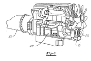
- FIGURE 1 is a perspective view of a vehicle transmission and engine equipped with an electric device of the present invention.
- FIGURE 2 is an end view a first embodiment of the present invention;
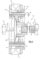
- FIGURE 3 is a side sectional view of the first embodiment of the present invention;
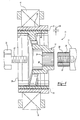
- FIGURE 4 is a side sectional view of a second embodiment of the present invention; and
- FIGURE 5 is a side sectional view of the first embodiment of the present invention, shown with a pulley mounted thereto.
- The following description of the preferred embodiments of the invention is not intended to limit the scope of the invention to these preferred embodiments, but rather to enable any person skilled in the art to make and use the invention. Referring to the Figures, wherein like numerals indicate like or corresponding parts throughout the several views, a rotor assembly of the present invention is shown generally at 10.
- Referring to Figures 2 and 3, a
rotor assembly 10 for an electric device comprises ahub 12 fixedly connectable to acrankshaft 14 of an engine, arotor 16 fixedly connected to saidhub 12 for operational engagement with a stator (not shown) of the electric machine, and anelastomeric dampener 18 disposed between and interconnecting thehub 12 and therotor 16 to dampen torsional vibration from the engine. - The electrical device is any type of electrical motor or generator which utilizes a stator and a rotor to either provide driving force when fed with an electrical current, or in the alternative, provides an electric current when provided with a driving force. Preferably, the electrical device is a starter/generator for a vehicle that provides both a starting motor to turn the crankshaft when the vehicle is started, and a generator to provide an electric output when the vehicle is running.
- The
rotor 16 is attached to afront end 20 of thecrankshaft 14 on a front side of the engine, such that when thecrankshaft 14 of the engine rotates therotor 16 will be driven rotationally. In the preferred embodiment, thefront end 20 of thecrankshaft 14 includes an end that has anouter diameter 22 and thehub 12 includes acentre aperture 24 with aninner diameter 26. In the preferred embodiment, theinner diameter 26 of thecentre aperture 24 and theouter diameter 22 of thefront end 20 of thecrankshaft 14 are sized to allow thehub 12 to be forced onto thefront end 20 of thecrankshaft 14, thereby forming a press fit condition. Preferably, thefront end 20 of thecrankshaft 14 further includes a threadedbore 28 extending longitudinally into thecrankshaft 14. Afastener 30 is threadingly engaged within the threadedbore 28. Thefastener 30 includes ahead portion 32 which has a diameter which is larger that theinner diameter 26 of thecentre aperture 24 within thehub 12 so that thefastener 30 provides additional support to maintain thehub 12 in a press fit condition onto thefront end 20 of thecrankshaft 14. - In a first preferred embodiment, the
hub 12 includes anouter flange 34 that includes a plurality of threadedbores 36 spaced radially about anouter diameter 38 of theouter flange 34. Therotor 16 includes aninner diameter 40 with a plurality ofapertures 42 spaced radially about therotor 16 for receivingfasteners 44 that extend through theapertures 42 in therotor 16 and threadingly engage the threadedbores 36 of theouter flange 34 to secure therotor 16 to theouter flange 34. - Referring to Figure 4, in a second embodiment, the
inner diameter 40 of therotor 16 and theouter diameter 38 of theouter flange 34 are sized to allow therotor 16 to be forced onto theouter diameter 38 of theouter flange 34, thereby forming a press fit condition and securing therotor 16 to theouter flange 34. - In both the first and second embodiments, the
outer flange 34 is attached to anouter diameter 46 of thehub 12. Theouter diameter 46 of thehub 12 is smaller than aninner diameter 48 of theouter flange 34, thereby leaving agap 50 between thehub 12 and theouter flange 34 extending radially around thehub 12. In the preferred embodiment, an elastomeric material is disposed between and interconnects theouter flange 34 to thehub 12. Theelastomeric material 18 provides semi rigid support to securely hold theouter flange 34 onto thehub 12, while providing torsional dampening to thecrankshaft 14. - Preferably, the
elastomeric material 18 is a tough durable material, such as rubber, which will securely support theouter flange 34 androtor 16, while being compliant to allow slight rotational movement between thehub 12 and theouter flange 34, thereby providing torsional dampening to the system. Preferably, theelastomeric material 18 is moulded in place between thehub 12 and theouter flange 34 by placing thehub 12 and theouter flange 34 within a mould, and disposing theelastomeric material 18 into thegap 50. The surfaces of theinner diameter 48 of theouter flange 34 and theouter diameter 46 of thehub 12 are preferably prepared ahead of time to provide surfaces to which theelastomeric material 18 will bond when cured. The surface preparation of theinner diameter 48 of theouter flange 34 and theouter diameter 46 of thehub 12 are selected based upon theelastomeric material 18 chosen for the application. It is to be understood, that any type ofelastomeric material 18 could be used, based upon the mechanical and environmental characteristics that the starter/generator is designed for. It is also to be understood, that theelastomeric material 18 could be placed between theouter flange 34 and thehub 12 and attached to the surfaces of theouter flange 34 and thehub 12 by other suitable methods. - Referring to Figure 1, preferably, the electric device is mountable to a vehicle drive train, wherein the drive train includes an
engine 54, acrankshaft 14 on the engine, and atransmission 56.. Thehub 12 is fixedly connectable to thecrankshaft 14 of the engine, while the stator (not shown) is mountable to the engine independently of thecrankshaft 14. Thehub 12 is mounted to thecrankshaft 14 on an end of the engine opposite the transmission. Therotor 16 is fixedly connected to theouter flange 34 of thehub 12 and disposed within the stator for operational engagement with the stator. Theelastomeric dampener 18 is disposed between and interconnects thehub 12 and theouter flange 34 to provide torsional dampening to thecrankshaft 14. In the preferred embodiment, thehub 12 is connectable to thecrankshaft 14 on a side of the engine opposite the transmission. - Preferably, the electric device has two modes of operation, such as a starter/generator. The first mode of operation is as an electric starter for the
engine 54. When an electric current is fed to the starter generator, therotor 16 rotates within the stator thereby forcing thecrankshaft 14 to rotate correspondingly. This mode is used to provide initial rotation of thecrankshaft 14 to start theengine 54. The second mode of operation is as a generator. After theengine 54 is started, the electric current being fed to the starter/generator is cut off. As thecrankshaft 14 spins under the power of theengine 54, therotor 16 continues to rotate within the stator, thereby generating electrical energy which can be fed from the starter/generator to be used elsewhere in the vehicle. - Although the
elastomeric material 18 disposed between thehub 12 and theouter flange 34 provides torsional dampening to the system, there still may be a need for apulley 52 mounted on thefront end 20 of thecrankshaft 14 to drive various components of the vehicle. Referring to Figure 5, therotor assembly 10 can include apulley 52 mounted onto thehub 12 for driving a belt (not shown) that can be routed to other components of thevehicle engine 54, such as an air conditioning compressor. Thepulley 52 can be mounted to arotor assembly 10 with either a bolted onrotor 16 or a pressfit rotor 16. - The foregoing discussion discloses and describes three preferred embodiments of the invention. One skilled in the art will readily recognize from such discussion, and from the accompanying drawings and claims, that changes and modifications can be made to the invention without departing from the scope of the invention as defined in the following claims. The invention has been described in an illustrative manner, and it is to be understood that the terminology which has been used is intended to be in the nature of words of description rather than of limitation.
Claims (9)
- A rotor assembly for an electric device comprising:a hub fixedly connectable to a crankshaft of an engine;a rotor fixedly connected to said hub for operational engagement with a stator of the electric device; andan elastomeric material disposed between and interconnecting said hub and said rotor to provide torsional dampening.
- The rotor assembly of claim 1 wherein said hub includes an inner diameter sized to allow said hub to be press fit onto an end of the crankshaft and held thereto by a bolt threaded into the end of the crankshaft.
- The rotor assembly of claim 1 wherein said hub includes an outer flange and said rotor is attached to said outer flange with threaded fasteners spaced radially about said hub.
- The rotor assembly of claim 1 wherein said hub includes an outer flange and said rotor includes an inner diameter, said outer flange and said inner diameter being sized to allow said rotor to be press fit onto said outer flange and held securely thereto.
- A drivetrain for a motor vehicle comprising:an engine including a crankshaft for transferring power therefrom;a transmission coupled to said engine;an electric device mounted to said engine opposite said transmission, said electric device including a hub fixedly connected to said crankshaft, a stator mounted to said engine independently of said crankshaft, a rotor fixedly connected to said hub and disposed within said stator for operational engagement with said stator, and an elastomeric material disposed between and interconnecting said hub and said rotor to provide torsional dampening.
- The drivetrain of claim 5 wherein said electric machine has a first mode of operation as an electric starter for said engine, and a second mode of operation as a generator.
- The drivetrain of claim 5 or 6 wherein said hub is press fit onto an end of the crankshaft and held thereto by a bolt threaded into the end of the crankshaft.
- The drivetrain of claim 5 or 6 wherein said hub includes an outer flange and said rotor is attached to said outer flange with threaded fasteners spaced radially about said hub.
- The drivetrain of claim 5 or 6 wherein said hub includes an outer flange and said rotor includes an inner diameter, said outer flange and said inner diameter being sized to allow said rotor to be press fit onto said outer flange and held securely thereto.
Applications Claiming Priority (2)
| Application Number | Priority Date | Filing Date | Title |
|---|---|---|---|
| US09/915,791 US20030020337A1 (en) | 2001-07-26 | 2001-07-26 | Electric machine rotor with crankshaft torsional damper |
| US915791 | 2001-07-26 |
Publications (1)
| Publication Number | Publication Date |
|---|---|
| EP1280256A1 true EP1280256A1 (en) | 2003-01-29 |
Family
ID=25436255
Family Applications (1)
| Application Number | Title | Priority Date | Filing Date |
|---|---|---|---|
| EP02254363A Withdrawn EP1280256A1 (en) | 2001-07-26 | 2002-06-21 | Electric machine rotor with crankshaft torsional damper |
Country Status (2)
| Country | Link |
|---|---|
| US (1) | US20030020337A1 (en) |
| EP (1) | EP1280256A1 (en) |
Cited By (2)
| Publication number | Priority date | Publication date | Assignee | Title |
|---|---|---|---|---|
| US20180142762A1 (en) * | 2012-12-13 | 2018-05-24 | Vibracoustic North America, L.P. | Propshaft damper and method of assembly |
| DE102020114608A1 (en) | 2020-06-02 | 2021-12-02 | Winkelmann Powertrain Components GmbH & Co. KG. | rotor |
Families Citing this family (6)
| Publication number | Priority date | Publication date | Assignee | Title |
|---|---|---|---|---|
| CN101473144B (en) * | 2006-05-16 | 2013-09-04 | 雷勃电气美国公司 | Vibration damping rotor assembly for rotating machinery |
| RU2410440C1 (en) * | 2007-08-16 | 2011-01-27 | Моринага Милк Индастри Ко., Лтд. | Method and set for microorganism detection |
| US20090145261A1 (en) * | 2007-12-06 | 2009-06-11 | Richard Obeshaw | Single mass dual mode crankshaft damper with tuned hub |
| US9013074B2 (en) | 2010-05-25 | 2015-04-21 | Regal Beloit America, Inc. | Resilient rotor assembly for interior permanent magnet motor |
| CN107852053B (en) * | 2015-08-05 | 2020-10-23 | 三菱电机株式会社 | Motor rotors, motors, blowers, and refrigeration and air conditioners |
| JP7014763B2 (en) * | 2019-11-05 | 2022-02-01 | シナノケンシ株式会社 | Lead screw device |
Citations (4)
| Publication number | Priority date | Publication date | Assignee | Title |
|---|---|---|---|---|
| US3694661A (en) * | 1968-10-18 | 1972-09-26 | Hitachi Ltd | Ac generator directly coupled to an internal combustion engine |
| DE3008430A1 (en) * | 1980-03-05 | 1981-09-10 | Robert Bosch Gmbh, 7000 Stuttgart | Three=phase alternator for motor vehicles - with polyurethane noise absorption layer between rotor shaft and rotor |
| EP1039619A2 (en) * | 1999-03-24 | 2000-09-27 | Honda Giken Kogyo Kabushiki Kaisha | Starter/generator apparatus for four-cycle internal combustion engine |
| DE10017396A1 (en) * | 2000-04-07 | 2001-10-11 | Volkswagen Ag | Electric machine for motor vehicle starter or generator, has at least one stator fixed in housing, and at least one rotor rotationally located on drive shaft radially outside stator |
Family Cites Families (12)
| Publication number | Priority date | Publication date | Assignee | Title |
|---|---|---|---|---|
| US3078737A (en) * | 1959-11-12 | 1963-02-26 | Schwitzer Corp | Tuned friction damper |
| US3058371A (en) * | 1960-11-29 | 1962-10-16 | Fred L Haushalter | Vibration dampener |
| US3545301A (en) * | 1969-06-02 | 1970-12-08 | Cincinnati Milacron Inc | Stepping motor damper |
| US5097140A (en) * | 1991-05-07 | 1992-03-17 | Chrysler Corporation | Alternator starter |
| DE19631384C1 (en) * | 1996-08-02 | 1997-10-16 | Clouth Gummiwerke Ag | Electric machine with rotor in drive train e.g. of motor vehicle |
| DE19747963A1 (en) * | 1997-10-30 | 1999-05-12 | Bayerische Motoren Werke Ag | Torque converter connection with vibration damper |
| JPH11159576A (en) * | 1997-11-28 | 1999-06-15 | Nok Megurasutikku Kk | Damper |
| JP3381613B2 (en) * | 1998-03-20 | 2003-03-04 | 日産自動車株式会社 | Drive control device for hybrid vehicle |
| US6026140A (en) * | 1998-04-21 | 2000-02-15 | Seiko Communications Systems Inc. | Low power programmable ripple counter |
| US6290692B1 (en) * | 1998-11-03 | 2001-09-18 | Daniel J. Klima | Catheter support structure |
| DE19916459A1 (en) * | 1999-04-12 | 2000-10-26 | Bosch Gmbh Robert | Starter generator for a motor vehicle |
| US6204577B1 (en) * | 2000-01-05 | 2001-03-20 | Jeffrey Eliot Chottiner | Method and apparatus for space-saving installation of a starter-alternator |
-
2001
- 2001-07-26 US US09/915,791 patent/US20030020337A1/en not_active Abandoned
-
2002
- 2002-06-21 EP EP02254363A patent/EP1280256A1/en not_active Withdrawn
Patent Citations (4)
| Publication number | Priority date | Publication date | Assignee | Title |
|---|---|---|---|---|
| US3694661A (en) * | 1968-10-18 | 1972-09-26 | Hitachi Ltd | Ac generator directly coupled to an internal combustion engine |
| DE3008430A1 (en) * | 1980-03-05 | 1981-09-10 | Robert Bosch Gmbh, 7000 Stuttgart | Three=phase alternator for motor vehicles - with polyurethane noise absorption layer between rotor shaft and rotor |
| EP1039619A2 (en) * | 1999-03-24 | 2000-09-27 | Honda Giken Kogyo Kabushiki Kaisha | Starter/generator apparatus for four-cycle internal combustion engine |
| DE10017396A1 (en) * | 2000-04-07 | 2001-10-11 | Volkswagen Ag | Electric machine for motor vehicle starter or generator, has at least one stator fixed in housing, and at least one rotor rotationally located on drive shaft radially outside stator |
Cited By (2)
| Publication number | Priority date | Publication date | Assignee | Title |
|---|---|---|---|---|
| US20180142762A1 (en) * | 2012-12-13 | 2018-05-24 | Vibracoustic North America, L.P. | Propshaft damper and method of assembly |
| DE102020114608A1 (en) | 2020-06-02 | 2021-12-02 | Winkelmann Powertrain Components GmbH & Co. KG. | rotor |
Also Published As
| Publication number | Publication date |
|---|---|
| US20030020337A1 (en) | 2003-01-30 |
Similar Documents
| Publication | Publication Date | Title |
|---|---|---|
| CN101619757B (en) | Dual ratio belt drive system | |
| US6311495B1 (en) | Composite power unit | |
| US6599214B2 (en) | Approach to integrating a starter-generator with an automatic transmission | |
| US8356584B2 (en) | Flywheel arrangement for an internal combustion engine | |
| US20150285312A1 (en) | Isolator for use with mgu that is used to assist or start engine through and endless drive member | |
| US20170306836A1 (en) | Endless drive arrangement with tensioning system and isolation device | |
| WO2014056097A1 (en) | Isolator for use with engine that is assisted or started by an mgu or a motor through an endless drive member | |
| JP2000516326A (en) | Electric machine in power train of automobile and operation method thereof | |
| CN101208534A (en) | Overspeed decoupler with locking mechanism | |
| KR20080110867A (en) | One-way isolation device for high torque machines | |
| US7472768B2 (en) | Drive system, especially for a motor vehicle | |
| CN111828499B (en) | Multi-mode integrated starter-generator device with magnetic cam assembly | |
| US20030020337A1 (en) | Electric machine rotor with crankshaft torsional damper | |
| US6781272B2 (en) | Integrated torque converter and starter-generator | |
| CN100458211C (en) | Inertial torque reaction management with selectively engageable counter rotating component | |
| JPH0814145A (en) | Motor-generating device for vehicle | |
| CN112543713B (en) | Polygonal spring coupler | |
| US9550412B2 (en) | Power generation system and method for assembling the same | |
| CN102820735A (en) | Automotive generator mechanism | |
| CN102673400A (en) | Electric generator system of electric compressor for automobile air conditioner | |
| US12529331B2 (en) | Motor-generator, power generation apparatus, and mobility device | |
| CN102684382A (en) | Power generator system of motor compressor for automobile air conditioner | |
| KR20220027554A (en) | Sub-pulley for mounting alternator | |
| CN102817708A (en) | Automotive generator unit | |
| CN102673401A (en) | Electric generator device of electric compressor for automobile air conditioner |
Legal Events
| Date | Code | Title | Description |
|---|---|---|---|
| PUAI | Public reference made under article 153(3) epc to a published international application that has entered the european phase |
Free format text: ORIGINAL CODE: 0009012 |
|
| AK | Designated contracting states |
Designated state(s): AT BE CH CY DE DK ES FI FR GB GR IE IT LI LU MC NL PT SE TR |
|
| AX | Request for extension of the european patent |
Extension state: AL LT LV MK RO SI |
|
| 17P | Request for examination filed |
Effective date: 20030312 |
|
| 17Q | First examination report despatched |
Effective date: 20030512 |
|
| AKX | Designation fees paid |
Designated state(s): DE FR GB |
|
| STAA | Information on the status of an ep patent application or granted ep patent |
Free format text: STATUS: THE APPLICATION IS DEEMED TO BE WITHDRAWN |
|
| 18D | Application deemed to be withdrawn |
Effective date: 20031125 |