EP1280226A1 - Tragbares funkgerät - Google Patents
Tragbares funkgerät Download PDFInfo
- Publication number
- EP1280226A1 EP1280226A1 EP00917401A EP00917401A EP1280226A1 EP 1280226 A1 EP1280226 A1 EP 1280226A1 EP 00917401 A EP00917401 A EP 00917401A EP 00917401 A EP00917401 A EP 00917401A EP 1280226 A1 EP1280226 A1 EP 1280226A1
- Authority
- EP
- European Patent Office
- Prior art keywords
- cover
- portable radio
- notch
- antenna
- casing
- Prior art date
- Legal status (The legal status is an assumption and is not a legal conclusion. Google has not performed a legal analysis and makes no representation as to the accuracy of the status listed.)
- Withdrawn
Links
Images


Classifications
-
- H—ELECTRICITY
- H01—ELECTRIC ELEMENTS
- H01Q—ANTENNAS, i.e. RADIO AERIALS
- H01Q1/00—Details of, or arrangements associated with, antennas
- H01Q1/08—Means for collapsing antennas or parts thereof
-
- H—ELECTRICITY
- H01—ELECTRIC ELEMENTS
- H01Q—ANTENNAS, i.e. RADIO AERIALS
- H01Q1/00—Details of, or arrangements associated with, antennas
- H01Q1/08—Means for collapsing antennas or parts thereof
- H01Q1/084—Pivotable antennas
-
- H—ELECTRICITY
- H01—ELECTRIC ELEMENTS
- H01Q—ANTENNAS, i.e. RADIO AERIALS
- H01Q1/00—Details of, or arrangements associated with, antennas
- H01Q1/12—Supports; Mounting means
- H01Q1/22—Supports; Mounting means by structural association with other equipment or articles
- H01Q1/24—Supports; Mounting means by structural association with other equipment or articles with receiving set
- H01Q1/241—Supports; Mounting means by structural association with other equipment or articles with receiving set used in mobile communications, e.g. GSM
- H01Q1/242—Supports; Mounting means by structural association with other equipment or articles with receiving set used in mobile communications, e.g. GSM specially adapted for hand-held use
-
- H—ELECTRICITY
- H01—ELECTRIC ELEMENTS
- H01Q—ANTENNAS, i.e. RADIO AERIALS
- H01Q13/00—Waveguide horns or mouths; Slot antennas; Leaky-waveguide antennas; Equivalent structures causing radiation along the transmission path of a guided wave
- H01Q13/10—Resonant slot antennas
-
- H—ELECTRICITY
- H04—ELECTRIC COMMUNICATION TECHNIQUE
- H04B—TRANSMISSION
- H04B1/00—Details of transmission systems, not covered by a single one of groups H04B3/00 - H04B13/00; Details of transmission systems not characterised by the medium used for transmission
- H04B1/38—Transceivers, i.e. devices in which transmitter and receiver form a structural unit and in which at least one part is used for functions of transmitting and receiving
- H04B1/3827—Portable transceivers
- H04B1/3833—Hand-held transceivers
Definitions
- the present invention relates generally to portable radio or mobile radio sets and particularly to those having a housing (hereinafter referred to as a "cover”) opened and closed, as desired, and provided with an antenna.
- a housing hereinafter referred to as a "cover”
- antenna an antenna
- This cover antenna has first and second components and when the cover is opened the first component is tuned in to an operating frequency of a transmission and reception circuit and when the cover is dosed the second component is tuned in to the operating frequency of the transmission and reception circuit. As such whether the cover is opened or closed the cover antenna can be tuned in to the operation frequency of the transmission and reception circuit.
- the radio communication apparatus disclosed in the above document would have a cover provided with two substantial antennas and these antennas that are coupled are a concern as antenna efficiency may be decreased. Furthermore the cover antenna as described above would require two power feed lines which are also difficult to provide as they are required to be provided at a connection (a hinge) of the cover and the housing.
- An object of the present invention is to provide a portable radio or mobile radio set having a cover opened and dosed, as desired, and provided with an antenna, wherein provision of a power feed line can be facilitated while reduction of antenna efficiency can be prevented.
- the present invention provides a portable radio including: a casing ; a cover attached to the casing and opened and closed as desired; an antenna formed by providing a notch in a conductive layer incorporated in the cover; and power supply or feeding means for exciting the antenna.
- the cover can incorporate a conductive layer notched to form an antenna, as described above, even with the cover closed a wide band can be ensured for a return loss of approximately no more than - 6dB, as shown in Fig. 2. As such, whether the cover is opened or closed, a single antenna can be sufficient and it is no longer necessary to provide the cover with two antennas, as conventional. Consequently, reduction of antenna efficiency can be reduced. Since a single antenna suffices a single power feeding line accordingly suffices and it can thus readily be provided.
- the conductive layer is provided substantially throughout the cover and the notch starts from an end of the cover free of a connection to the casing and extends in the cover inwardly.
- the notch preferably extends in the direction of the length of the casing. This allows a polarized wave to be provided in a direction orthogonal to the direction of the length of the casing to produce vertical polarization in use.
- the notch has a length corresponding to one fourth of a wavelength.
- the notch as seen lengthwise has one end larger in width than the other end.
- a further increased band can be provided if the one end of the notch as seen lengthwise is positioned opposite a connection of the cover and the casing or corresponds to a top end of the notch (an end thereof that is opened). Furthermore, if it is positioned closer to the connection of the cover and the casing or closer to a foot of the notch, the notch can be reduced in length.
- the notch may at least partially be bent in geometry. This can also reduce the notch in length.
- the casing is provided with a resonator excited by the antenna.
- the resonator may be a 1 ⁇ 4 wavelength resonator having one end with short circuit and the other end with open circuit or a 1 ⁇ 2 wavelength resonator having opposite ends with open circuit.
- the resonator is preferably positioned to be adjacent to the antenna when the cover is closed.
- the present portable radio preferably includes: first and second matching circuits; detection means detecting whether the cover is open or closed; a first switch switching according to a result obtained from the detection means, to connect the first and second matching circuits to the antenna; and a second switch switching according to a result obtained from the detection means, to connect the first and second matching circuits to the power feeding means.
- Fig. 1 schematically shows a configuration of a portable radio or mobile radio set 1, such as a mobile wireless phone, in a first embodiment of the present invention.
- portable radio 1 includes a casing 2, a cover or flip 3 opened and closed, as desired, an antenna 5 and a power feed means 6.
- Cover 3 is formed of dielectric material such as organic polymer and it internally has antenna 5.
- Antenna 5 is formed by providing a notch 4 in a conductive layer provided to cover 3.
- the conductive layer is formed for example of metal and it can for example be plated or provided through vapor deposition.
- the conductive layer has a U-letter, planar geometry and it is provided across substantially throughout cover 3.
- notch 4 extends in a direction of a length of casing 2, extending in cover 3 inwardly starting from an end of cover 3 that is not connected to casing 2.
- Notch 4 has a length L1 preferably of one forth of a wavelength ( ⁇ / 4 ).
- antenna 5 as described above is provided in cover 3, with cover 3 closed a wide bandwidth of approximately 130 MHz is provided for a return loss of no more than - 6dB.
- cover 3 is opened or closed, a single antenna 5 is sufficient and it is no longer necessary to provide the cover with two antennas, as conventional. This can reduce reduction of antenna efficiency and also reduce the number of power feed lines.
- a notch 4a is different in geometry from notch 4 of the first embodiment. More specifically, notch 4a is wider at an end located opposite a connection of cover 3 and casing 2 (an end moving away from casing 2 when cover is opened). The remainder of the configuration is similar to the Fig. 1 example.
- notch 4a having an end increased in width results in a further increased bandwidth of approximately 150 MHz for the return loss of no more than - 6dB with cover 3 closed.
- the present embodiment can provide a further increased bandwidth.
- notch 4a linearly tapers to have a gradually increasing width it may have any other forms that can permit notch 4a to be larger in width at a top than a bottom or root. Also note that notch 4a has a length L2 for example of ⁇ divided by four.
- notch 4 has a foot or short circuit 7 located closer to a connection of cover 3 and casing 2 and having a width W2 larger than a width W1 of a portion of notch 4 other than foot 7.
- the remainder of the configuration is similar to the Fig. 1 example.
- Notch 4 has width W1 for example of approximately ⁇ divided by 40 and width W2 preferably of approximately three times width W1 since notch 4 having foot 7 with large width W2 allows notch 4 to be reduced in a length L3 and thus antenna 5 to be compact.
- foot 7 is rectangular in geometry it may have any geometry selected as desired that has width W2 larger than width W1.
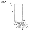
- a notch 4c meanders.
- notch 4 may have only a foot 8 meandering.
- the remainder of the configuration is similar to the Fig. 1 example.
- At least partially meandering notch 4, 4c, as described above, can be reduced in lengths L4 and L5 and thus allow antenna 5 to be compact.
- casing 2 is provided with a resonator 9.
- the remainder of the configuration is similar to the Fig. 1 example.
- Resonator 9 is positioned to be adjacent to antenna when cover 3 is closed, and it is excited by antenna 5 contactless.
- resonator 9 may have one end with short circuit and the other end with open circuit to be a ⁇ / 4 resonator (a resonator having a length L6 of ⁇ divided by four) or it may have opposite ends with open circuit to be a ⁇ / 2 resonator.
- portable radio 1 includes first and second matching circuits 12 and 13, means 14 for detecting whether cover 3 is open or closed, and first and second switches 10 and 11.
- the first matching circuit 12 is connected to antenna 5 when cover 3 is opened.
- the second matching circuit 13 is connected to antenna 5 when cover 3 is closed. In parallel with the second matching circuit 13 is provided a resonation circuit (not shown).
- Means 14 can for example be that as disclosed in Japanese Patent Laying-Open No. 6-291820. A result obtained from mean 14 is referred to to control the first and second switches 10 and 11.
- the first switch 10 switches to connect the first and second matching circuits 12 and 13 to antenna 5, as described above.
- the second switch 11 switches to connect the first and second matching circuits 12 and 13 to power feeding means 6. That is, when cover 3 is opened the first matching circuit 12 is connected to power feeding means 6 and when cover 3 is closed the second matching circuit 13 is connected to power feeding means 6.
- the present invention is usefully applicable to portable radios with a casing provided with a cover or flip opened and closed, as desired, and provided with an antenna.
Applications Claiming Priority (1)
| Application Number | Priority Date | Filing Date | Title |
|---|---|---|---|
| PCT/JP2000/002608 WO2001082408A1 (fr) | 2000-04-20 | 2000-04-20 | Dispositif radio portable |
Publications (2)
| Publication Number | Publication Date |
|---|---|
| EP1280226A1 true EP1280226A1 (de) | 2003-01-29 |
| EP1280226A4 EP1280226A4 (de) | 2004-10-06 |
Family
ID=11735951
Family Applications (1)
| Application Number | Title | Priority Date | Filing Date |
|---|---|---|---|
| EP00917401A Withdrawn EP1280226A4 (de) | 2000-04-20 | 2000-04-20 | Tragbares funkgerät |
Country Status (3)
| Country | Link |
|---|---|
| EP (1) | EP1280226A4 (de) |
| CN (1) | CN1357161A (de) |
| WO (1) | WO2001082408A1 (de) |
Cited By (7)
| Publication number | Priority date | Publication date | Assignee | Title |
|---|---|---|---|---|
| WO2003052867A1 (en) | 2001-12-18 | 2003-06-26 | Nokia Corporation | Monopole slot antenna |
| WO2006061733A2 (en) * | 2004-12-06 | 2006-06-15 | Koninklijke Philips Electronics N.V. | Antenna having conductive planes connected by a conductive bridge |
| US7318268B2 (en) | 2001-11-09 | 2008-01-15 | Hitachi Cable, Ltd. | Method for making flat antenna |
| US7369885B2 (en) | 2003-01-08 | 2008-05-06 | Sony Ericsson Mobile Communications Japan, Inc. | Radio device and cellular phone having a notch with a bent-back portion |
| EP2110962A1 (de) | 2008-04-17 | 2009-10-21 | Laird Technologies AB | Schlitz- und Stabantennas in tragbrem Funkkummunikationsgerät der aufschibaren art |
| EP2637249A1 (de) * | 2012-03-08 | 2013-09-11 | Acer Incorporated | Einstellbare Schlitzantenne |
| EP2907197A1 (de) * | 2012-10-15 | 2015-08-19 | Intel Corporation | Antennenelement und vorrichtungen dafür |
Families Citing this family (5)
| Publication number | Priority date | Publication date | Assignee | Title |
|---|---|---|---|---|
| JP4067041B2 (ja) * | 2002-06-04 | 2008-03-26 | 好伸 岡野 | プレートアンテナおよびそのアンテナを備える通信端末 |
| JP3844717B2 (ja) | 2002-07-19 | 2006-11-15 | ソニー・エリクソン・モバイルコミュニケーションズ株式会社 | アンテナ装置および携帯無線通信端末 |
| JP2004208223A (ja) * | 2002-12-26 | 2004-07-22 | Alps Electric Co Ltd | 2バンド共用パッチアンテナ |
| US7994987B2 (en) * | 2008-05-21 | 2011-08-09 | Motorola Solutions, Inc. | Notched antenna structure with a stepped shaped element |
| JP5773071B2 (ja) | 2012-04-02 | 2015-09-02 | 株式会社村田製作所 | アンテナ装置 |
Citations (2)
| Publication number | Priority date | Publication date | Assignee | Title |
|---|---|---|---|---|
| EP0518526B1 (de) * | 1991-05-31 | 1995-08-23 | Nec Corporation | Tragbares und klappbares Funkgerät |
| US5608413A (en) * | 1995-06-07 | 1997-03-04 | Hughes Aircraft Company | Frequency-selective antenna with different signal polarizations |
Family Cites Families (5)
| Publication number | Priority date | Publication date | Assignee | Title |
|---|---|---|---|---|
| JPH0766614A (ja) * | 1993-08-24 | 1995-03-10 | Oki Electric Ind Co Ltd | リトラクタブルアンテナ |
| US5561436A (en) * | 1994-07-21 | 1996-10-01 | Motorola, Inc. | Method and apparatus for multi-position antenna |
| JP2944444B2 (ja) * | 1995-01-12 | 1999-09-06 | 日本電気株式会社 | 携帯無線機 |
| JPH09270618A (ja) * | 1996-03-29 | 1997-10-14 | Mitsubishi Electric Corp | アンテナ装置 |
| GB2335081B (en) * | 1998-03-05 | 2002-04-03 | Nec Technologies | Antenna for mobile telephones |
-
2000
- 2000-04-20 WO PCT/JP2000/002608 patent/WO2001082408A1/ja not_active Application Discontinuation
- 2000-04-20 CN CN00809251.6A patent/CN1357161A/zh active Pending
- 2000-04-20 EP EP00917401A patent/EP1280226A4/de not_active Withdrawn
Patent Citations (2)
| Publication number | Priority date | Publication date | Assignee | Title |
|---|---|---|---|---|
| EP0518526B1 (de) * | 1991-05-31 | 1995-08-23 | Nec Corporation | Tragbares und klappbares Funkgerät |
| US5608413A (en) * | 1995-06-07 | 1997-03-04 | Hughes Aircraft Company | Frequency-selective antenna with different signal polarizations |
Non-Patent Citations (1)
| Title |
|---|
| See also references of WO0182408A1 * |
Cited By (9)
| Publication number | Priority date | Publication date | Assignee | Title |
|---|---|---|---|---|
| US7318268B2 (en) | 2001-11-09 | 2008-01-15 | Hitachi Cable, Ltd. | Method for making flat antenna |
| WO2003052867A1 (en) | 2001-12-18 | 2003-06-26 | Nokia Corporation | Monopole slot antenna |
| US7369885B2 (en) | 2003-01-08 | 2008-05-06 | Sony Ericsson Mobile Communications Japan, Inc. | Radio device and cellular phone having a notch with a bent-back portion |
| WO2006061733A2 (en) * | 2004-12-06 | 2006-06-15 | Koninklijke Philips Electronics N.V. | Antenna having conductive planes connected by a conductive bridge |
| WO2006061733A3 (en) * | 2004-12-06 | 2006-09-08 | Koninkl Philips Electronics Nv | Antenna having conductive planes connected by a conductive bridge |
| EP2110962A1 (de) | 2008-04-17 | 2009-10-21 | Laird Technologies AB | Schlitz- und Stabantennas in tragbrem Funkkummunikationsgerät der aufschibaren art |
| EP2637249A1 (de) * | 2012-03-08 | 2013-09-11 | Acer Incorporated | Einstellbare Schlitzantenne |
| US9356356B2 (en) | 2012-03-08 | 2016-05-31 | Acer Incorporated | Tunable slot antenna |
| EP2907197A1 (de) * | 2012-10-15 | 2015-08-19 | Intel Corporation | Antennenelement und vorrichtungen dafür |
Also Published As
| Publication number | Publication date |
|---|---|
| WO2001082408A1 (fr) | 2001-11-01 |
| CN1357161A (zh) | 2002-07-03 |
| EP1280226A4 (de) | 2004-10-06 |
Similar Documents
| Publication | Publication Date | Title |
|---|---|---|
| KR101025680B1 (ko) | 안테나 장치 및 휴대 무선 통신 단말기 | |
| US6950065B2 (en) | Mobile communication device | |
| US6664931B1 (en) | Multi-frequency slot antenna apparatus | |
| US6650295B2 (en) | Tunable antenna for wireless communication terminals | |
| EP2160796B1 (de) | Antennenanordnung | |
| US6204826B1 (en) | Flat dual frequency band antennas for wireless communicators | |
| US6515625B1 (en) | Antenna | |
| US6933893B2 (en) | Electronically tunable planar antenna and method of tuning the same | |
| US20030045324A1 (en) | Wireless communication apparatus | |
| EP1263083A2 (de) | Invertierte F-Antenne und tragbares Kommunikationsgerät mit einer solchen Antenne | |
| EP1962372B1 (de) | Kleine, Breitbandigeantenne mit Induktive Chassiskopplung | |
| JP3830892B2 (ja) | 携帯無線機 | |
| JPWO2004047223A1 (ja) | 複数帯域用アンテナ | |
| JP2007510362A (ja) | 浮遊非励振素子を含むマルチバンド平板逆fアンテナと、それを組み込んだ無線端末 | |
| JP2007221288A (ja) | アンテナ装置及び無線通信装置 | |
| WO2006007161A2 (en) | Multi-frequency conductive-strip antenna system | |
| EP1280226A1 (de) | Tragbares funkgerät | |
| US20070139282A1 (en) | Antenna and portable wireless apparatus including the same | |
| KR20070065773A (ko) | 안테나 및 이를 채용한 휴대무선장치 | |
| GB2373637A (en) | Multi frequency band antenna | |
| Sheta et al. | Compact dual-band tunable microstrip antenna for GSM/DCS-1800 applications | |
| JP2005167730A (ja) | 多周波アンテナおよびそれを備えた情報端末機器 | |
| WO2001020714A1 (en) | Broadband or multi-band planar antenna | |
| JPH09232854A (ja) | 移動無線機用小型平面アンテナ装置 | |
| JP4240953B2 (ja) | チップアンテナ及び無線通信装置 |
Legal Events
| Date | Code | Title | Description |
|---|---|---|---|
| PUAI | Public reference made under article 153(3) epc to a published international application that has entered the european phase |
Free format text: ORIGINAL CODE: 0009012 |
|
| 17P | Request for examination filed |
Effective date: 20020117 |
|
| AK | Designated contracting states |
Designated state(s): AT BE CH CY DE DK ES FI FR GB GR IE IT LI LU MC NL PT SE |
|
| RBV | Designated contracting states (corrected) |
Designated state(s): DE FR GB |
|
| A4 | Supplementary search report drawn up and despatched |
Effective date: 20040820 |
|
| 17Q | First examination report despatched |
Effective date: 20041020 |
|
| STAA | Information on the status of an ep patent application or granted ep patent |
Free format text: STATUS: THE APPLICATION HAS BEEN WITHDRAWN |
|
| 18W | Application withdrawn |
Effective date: 20050322 |