EP1279952A1 - Analyzer and method of testing analyzer - Google Patents
Analyzer and method of testing analyzer Download PDFInfo
- Publication number
- EP1279952A1 EP1279952A1 EP01917855A EP01917855A EP1279952A1 EP 1279952 A1 EP1279952 A1 EP 1279952A1 EP 01917855 A EP01917855 A EP 01917855A EP 01917855 A EP01917855 A EP 01917855A EP 1279952 A1 EP1279952 A1 EP 1279952A1
- Authority
- EP
- European Patent Office
- Prior art keywords
- measurement
- electrical
- analyzer
- terminal
- response
- Prior art date
- Legal status (The legal status is an assumption and is not a legal conclusion. Google has not performed a legal analysis and makes no representation as to the accuracy of the status listed.)
- Granted
Links
Images








Classifications
-
- G—PHYSICS
- G01—MEASURING; TESTING
- G01N—INVESTIGATING OR ANALYSING MATERIALS BY DETERMINING THEIR CHEMICAL OR PHYSICAL PROPERTIES
- G01N27/00—Investigating or analysing materials by the use of electric, electrochemical, or magnetic means
- G01N27/26—Investigating or analysing materials by the use of electric, electrochemical, or magnetic means by investigating electrochemical variables; by using electrolysis or electrophoresis
- G01N27/416—Systems
- G01N27/4163—Systems checking the operation of, or calibrating, the measuring apparatus
- G01N27/4165—Systems checking the operation of, or calibrating, the measuring apparatus for pH meters
Definitions
- This invention relates to a device for measuring the concentration of a specific component in a sample liquid, and a method of testing such a device.
- One method for measuring the concentration of a specific component in a sample liquid is a method in which the specific component concentration is computed from the potential difference arising when a reference liquid containing a known concentration of the specific component and a sample liquid containing an unknown concentration of the specific component are electrically shunted.
- the concentration of the specific component is measured.
- concentrations of three types of specific components for example, K + , Na + , Cl -
- the analyzer has, at least, a set portion in which a plate for concentration measurement is set; three pairs of probes (for a total of six); and computation means to compute the concentration of the specific component from the potential differences between each pair of probes.
- the plate for concentration measurement has, at least, a reference liquid reception portion, onto which reference liquid is spot-applied; a reference liquid holding portion, which holds the reference liquid; first through third terminal portions, which are in electrical contact with the reference liquid of the reference liquid holding portion; a sample liquid reception portion, into which the sample liquid is spot-applied; a sample liquid holding portion, which holds the sample liquid; fourth through sixth terminal portions, which are in electrical contact with the sample liquid holding portion; and a bridge, which electrically shunts the reference liquid of the reference liquid holding portion and the sample liquid of the sample liquid holding portion.
- the corresponding probe of the analyzer is in contact with each of the terminal portions.
- potential differences between the reference liquid and sample liquid are measured for each specific component, via each probe pair.
- the computation means of the analyzer computes the concentrations of each specific component based on the potential difference measurement results.
- a check plate is set in the set portion, and the potential difference measurement electrical circuit is tested for defects.
- causes of electrical circuit defects include, for example, malfunctions of electronic parts, breakage in wiring, and contact failure between a probe and the concentration measurement plate (first through sixth terminal portion).
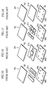
- the test method described in JP-B 6-82113 employs check plates 9A to 9D, as shown in Figs. 15 to 18 of this application.
- Each of these check plates 9A to 9D has a base plate 90 in which are provided a total of six through-holes 90a corresponding to three pairs of probes in the analyzer.
- On the base plate 90 is stacked a cover plate 92, enclosing conducting layers 91a to 91d.
- Various configurations for the conducting layers 91a to 91d are shown in Figs. 15 to 18.
- Each of these check plates 9A to 9D is set in the analyzer similarly to a test plate. At this time, each of the probes is in contact with the conducting layers 91a to 91d, so that each of the probe pairs is shunted. Test of the electrical circuit for potential difference measurement is performed by measuring the potential differences between the probe pairs. In this test method, if the potential difference between each probe pair is zero, the electrical circuit for potential difference measurement of the analyzer is judged to be normal, and if not zero, the circuit is judged to be abnormal.
- measured potentials are always zero, so that it is not possible to test reliably for the presence of defects in the electrical circuit for potential difference measurement. For example, even in a case in which a measurement value corresponding to the actual potential difference cannot be observed due to some abnormality, the measured value for the zero potential in tests is measured as either zero or as a value close to zero. In this case, it is judged that there is no abnormality in the electrical circuit for potential difference measurements. It is also difficult to determine the measurement precision for potentials which deviate greatly from zero potential.
- a check plate 9E such as shown in Fig. 19 is used.
- This check plate 9E has a base plate 90 in which are provided a total of six through-holes 90a corresponding to the three probe pairs of the analyzer.
- On this base plate 90 are placed six conducting pads 91e which separately cover each of the through-holes 90a.
- the conducting pads 91e, resistors R 1 to R 3 , and battery 91f are enclosed by the frame 92 positioned on the base plate 90.
- the space enclosed by the frame 92 is sealed with resin.
- a first aspect of this invention provides an analyzer for measuring a concentration of a specific component in a sample liquid supplied to the test piece with use of a test piece which has a first terminal portion and a second terminal portion, the analyzer comprising a set portion in which the test piece is set, a first measurement terminal for electrical connection to the first terminal portion and a second measurement terminal for electrical connection to the second terminal portion, and a measurement electrical circuit to measure parameters necessary to compute the concentration of the specific component; the analyzer further comprising test means to test the measurement electrical circuit using a check piece instead of the test piece; wherein the test means applying a plurality of electrical conditions to the check piece for testing the measurement electrical circuit based on a plurality of electrical responses obtained from the measurement electrical circuit when the electrical conditions are applied individually.
- the test means is designed to test the measurement electrical circuit by comparing each of the electrical responses with an ideal electrical response for each of the electrical conditions.
- the analyzer is designed to measure the potential difference occurring between a reference liquid having a known concentration of the specific component, and a sample liquid having an unknown concentration of the specific component.
- the check piece used has a first conducting portion for contact with the first measurement terminal and a second conducting portion for contact with the second measurement terminal.
- the first conducting portion and the second conducting portion are insulated from each other.
- the plurality of electrical conditions for example, a plurality of standard voltages are set.
- the plurality of standard voltages are, for example, at least two voltages selected from among positive values, zero, and negative values.
- At least one among the plurality of standard voltages be applied by supplying a voltage from the power supply to the first conducting portion, while grounding the second conducting portion.
- the voltage of the power supply is, for example, controlled using a regulator within the analyzer.
- the measurement electrical circuit is designed such that the current value is measured when a constant voltage is applied across the first terminal portion and the second terminal portion.
- the check piece used has a first conducting portion for contact with the first measurement terminal and a second conducting portion for contact with the second measurement terminal.
- the first conducting portion and the second conducting portion are electrically connected.
- the plurality of electrical conditions for example, a plurality of standard currents are set.
- the plurality of standard currents include, for example, positive values and zero.
- the measurement electrical circuit has a response measurement instrument which measures the electrical response, and is designed to apply an electrical condition to the response measurement instrument and calibrate the response measurement instrument.
- the check plate When testing the measurement electrical circuit, the check plate may be incorporated from outside the device, or may be incorporated into the device interior in advance.
- a second aspect of this invention provides a method of testing an analyzer for measuring a concentration of a specific component in a sample liquid supplied to a test piece having a first terminal portion and a second terminal portion; the analyzer comprising a set portion in which the test piece is set, a first measurement terminal for electrical connection to the first terminal portion, a second measurement terminal for electrical connection to the second terminal portion, and a measurement electrical circuit which measures parameters necessary to compute the concentration of the specific component, the method comprising: a first step for applying an electrical condition to the check piece; a second step for measuring an electrical response obtained from the measurement electrical circuit when the electrical condition is applied; and a third step for comparing the electrical response with an ideal electrical response obtainable when the electrical condition is applied to the check piece; wherein the first through third steps are performed separately for each of a plurality of electrical conditions.
- the measurement electrical circuit has a response measurement instrument to measure the electrical response, and a step is included in which, prior to the first step, an electrical condition is applied to the response measurement instrument, and the response measurement instrument is calibrated.
- a plurality of standard voltages, or a plurality of standard currents are set.
- the analyzer X1 of a first embodiment of this invention shown in Fig. 1, electrochemically measures the concentration of a specific component in a sample liquid through comparison with a reference liquid containing a known concentration of the specific component.
- the sample liquid may be, for example, blood, urine, saliva, or other biological samples, or liquids obtained by adjusting same.
- Specific components may be, for example, Na + , K + , or Cl - .
- a display 11 which displays measurement results and operating conditions
- a discharge portion 12 which discharges recording paper K.
- a pipette holder 2 On the front face of the analyzer X1 is provided a pipette holder 2. On the bottom of the pipette holder 2 is provided a set portion 3, in which is set a potential difference measurement plate 4 (see Fig. 4 through Fig. 6).
- the pipette holder 2 has a first space 20 which is penetrated vertically and open in the forward direction, and a second space 21 which is connected with the first space 20 below the first space 20, and is open in the forward direction, as shown in Fig. 1 and Fig. 2.
- the body portion 50 of the pipette 5 is accommodated by the first space 20, and the tip portions 51a, 51b of the pipette 5 as well as the tips Ta, Tb mounted on these portions are accommodated by the second space 21.
- a step 22 is formed between the first space 20 and second space 21.
- the bottom face 52 of the body portion 50 of the pipette 5 catches on the upper face 22a of this step 22.
- the pipette 5 shown in Fig. 2 is a double pipette.
- this pipette 5 by moving the operating portions 53a, 53b up and down, a prescribed quantity of liquid can be sucked in or discharged via the tip apertures of the tips Ta, Tb.
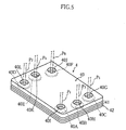
- the set portion 3 has an accommodating space 30 capable of holding a potential difference measurement plate 4 (see Fig. 4 through Fig. 6), as shown in Fig. 3.
- a potential difference measurement plate 4 see Fig. 4 through Fig. 6
- Three pairs (for a total of six) of probes P 1 through P 6 protrude upward from the bottom face 31 of this set portion 3.
- the potential differences arising from differences in concentration of, for example, K + , Na + , or Cl - between a reference liquid and a sample liquid are measured through these probe pairs P 1 to P 6 .
- the potential difference measurement plate 4 is formed by stacking a resist layer 41 and cover film 42 onto a base film 40, as shown in Fig. 4 through Fig. 6.
- the potential difference measurement plate 4 is configured so as to enable measurement of potential differences for three types of ions, for example Na + , K + , and Cl - .
- the base film layer 40 is electrically insulating.
- the base film layer 40 has a rectangular shape overall.
- Three terminals each, 40A to 40C and 40D to 40F, are formed on the two short edges of the base film layer 40.
- Each of the three sets of terminals 40A to 40C and 40D to 40F is arranged in the direction of the shorter edges of the base film layer 40.
- Through-holes 40G, 40H, 40I, 40J, 40K, 40L are formed corresponding to the terminals 40A to 40F at the two shorter edges of the base film layer 40.
- the probes P 1 to P 6 are in contact with the terminals 40A to 40F via the corresponding through-holes 40G to 40L.
- liquid-receiving pads 40a to 40f are formed in the center portion of the base film layer 40. Specific components of the reference liquid or sample liquid are supplied to these liquid-receiving pads 40a to 40f. Each of the liquid-receiving pads 40a to 40f is electrically connected to the corresponding terminals 40A to 40F via the conducting wires 40Aa, 40Bb, 40Cc, 40Dd, 40Ee, 40Ff.
- the resist film layer 41 comprises a first resist film layer 43, and a second resist film layer 44.
- the first resist film layer 43 and second resist film layer 44 are electrically insulating.
- the first resist film layer 43 and second resist film layer 44 have a rectangular shape overall.
- the ion selection films 45a, 45d selectively pass, for example, K + .
- the ion selection films 45b, 45e selectively pass, for example, Cl - .
- the ion selection films 45c, 45f selectively pass, for example, Na + .
- a reference liquid holding hole 43g and sample liquid holding hole 43h are formed in the center portion of the first resist film 43.
- the reference liquid holding hole 43g is connected to the three connecting holes 44a, 44b, 44c; the sample liquid holding hole 43h is connected to the three connecting holes 44d, 44e, 44f.
- the reference liquid holding hole 43g and sample liquid holding hole 43h are connected via a cutout 43i.
- a bridge 45i permitting the movement of ions is positioned in this cutout 43i.
- a reference liquid receiving aperture 42g and sample liquid receiving aperture 42h are formed in the center portion of the long side of the cover film layer 42.
- the reference liquid receiving aperture 42g is connected to the reference liquid holding hole 43g of the first resist film layer 43.
- the sample liquid receiving aperture 42h is connected to the sample liquid holding hole 43h of the first resist film 43.
- Two air vent holes 42j are formed in the cover film layer 42. Each of the air vent holes 42j is connected to both the reference liquid holding hole 43g and to the sample liquid holding hole 43h.
- the potential difference measurement plate 6 is set such that the reference liquid receiving aperture 42g and sample liquid receiving aperture 42h are opened upward. In this state, the terminals 40A to 40F of the potential difference measurement plate 4 are in contact with the corresponding probes P 1 to P 6 , as shown in Fig. 5.
- tips Ta, Tb are mounted on the tip portions 51a, 51b of the pipette 5 as shown in Fig. 2. Then, the reference liquid or sample liquids is drawn into the tips Ta, Tb by operating the operating portions 53a, 53b.
- the pipette 5 is held by the pipette holder 2 by catching the bottom face 52 of the body portion 50 on the upper face 22a of the step 22 of the pipette holder 2.
- the operating portions 53a, 53b of the pipette 5 are moved downward, to dispense the reference liquid R and sample liquid S from the tip apertures of the tips Ta, Tb respectively, as shown in Fig. 4.
- the reference liquid is spot-applied to the reference liquid receiving aperture 42g
- the sample liquid is spot-applied to the sample liquid receiving aperture 42h.
- the reference liquid R which is spot-applied from the reference liquid receiving aperture 42g is held by the reference liquid holding hole 43g
- the sample liquid S which is spot-applied from the sample liquid receiving aperture 42h is held by the sample liquid holding hole 43h. Because the reference liquid holding hole 43g and sample liquid holding hole 43h are connected via a cutout 43i in which a bridge 45i is positioned, the reference liquid R and sample liquid S are electrically shunted.
- the K + , Cl - and Na + ions in the reference liquid R held in the reference liquid holding hole 43g pass through the ion selection membranes 45a, 45b, 45c respectively, to reach the reference liquid-receiving pads 40a, 40b, 40c.
- the K + , Cl - and Na + ions in the sample liquid S held in the sample liquid holding hole 43h pass through the ion selection membranes 45d, 45e, 45f respectively, to reach the sample liquid-receiving pads 40d, 40e, 40f.
- This potential difference is measured by the potential difference measurement electrical circuit 6 shown in Fig. 7, via the three pairs of probes P 1 to P 6 .
- the potential difference arising from the difference in concentration of K + is measured by bringing the probes P 1 , P 2 into contact with the terminals 40A, 40D.
- the potential difference arising from the difference in concentration of Cl - is measured by bringing the probes P 3 , P 4 into contact with the terminals 40B, 40E.
- the potential difference arising from the difference in concentration of Na + is measured by bringing the probes P 5 , P 6 into contact with the terminals 40C, 40F.
- the potential difference measurement circuit 6 has a K + measurement circuit 60, Cl - measurement circuit 61, Na + measurement circuit 62, potential difference measurement instrument 63, power supply 64, computation portion 65, determination portion 66, and a plurality of analog switches S 1 to S 6 .
- the K + measurement circuit 60, Cl - measurement circuit 61, and Na + measurement circuit 62 have an impedance-matching system 60A, 61A, 62A, differential system 60B, 61B, 62B, and a low-pass filter 60C, 61C, 62C.
- the impedance-matching systems 60A, 62A of the K + measurement circuit 60 and Na + measurement circuit 62 amplify the inputs from the probes P 1 , P 2 , P 5 , P 6 , and have a pair of impedance-matching amplifiers 60Aa, 60Ab, 62Aa, 62Ab.
- the Cl - measurement circuit 61 amplifies the input from the probes P 3 , P 4 , and as the probe P 3 is grounded, the impedance-matching system 61A has a single impedance-matching amplifier 61a.
- the differential systems 60B, 61B, 62B have differential amplifiers 60b, 61b, 62b which differentiate the outputs from the amplifiers 60Aa, 60Ab, 61b, 62Aa, 62Ab of the impedance-matching systems 60A, 61A, 62A.
- the Cl - measurement circuit 61 because there is one impedance-matching amplifier 61a in the impedance-matching system 61A, one of the inputs to the differential amplifier 61b is zero.
- the low-pass filters 60C, 61C, 62C reduce the noise components, and each have a resistor and a capacitor.
- the potential difference measurement instrument 63 has, for example, an A/D converter 63a capable of potential difference measurement, and a knob-operated regulator 63b which calibrates this A/D converter 63a.
- the voltage of the power supply 64 is controlled by a regulator within the equipment.
- This power supply 64 is designed to be able to supply three types of voltage (standard voltages), 100 mV, 0 mV, and -100 mV, to the probe P 4 by switching an analog switch S 6 .
- the computation portion 65 computes the concentration of a specific component based on the potential difference measured by the A/D converter 63a.
- This computation portion 65 has, for example, a CPU, ROM, and RAM.
- Working curve data indicating the relation between the concentration of each specific component and the potential difference, and a program to compute the concentration of a specific component by applying measured potential differences to the working curve data, are stored in the ROM.
- the working curve data is created based on, for example, the Nernst equation.
- the determination portion 66 judges whether there is a defect in the potential difference measurement circuit 6.
- This determination portion 66 has, for example, a CPU, ROM, and RAM. Ideal response voltage values for each standard voltage, and a program which compares response voltage values actually measured by the A/D converter 63a at each standard voltage and judges whether there is a defect in the potential difference measurement circuit 6, for example, are stored in the ROM.
- the computation portion 65 and determination portion 66 may be configured so as to share the CPU and RAM.
- Each of the measurement circuits 60, 61, 62 can be separately driven and powered by turning on and off the plurality of analog switches S 1 through S 6 .
- potential difference measurements for K + , Cl - , or Na + are performed as follows.
- the analog switch S 1 is closed, and the analog switches S 2 , S 3 , S 4 , and S 5 are opened.
- the output from the probes P 1 , P 2 is input to each of the amplifiers 60Aa, 60Ab of the impedance-matching system 60A, and is amplified.
- the outputs from the amplifiers 60Aa, 60Ab are differentiated by the differentiating amplifier 60b. This difference is equivalent to the difference in inputs (potential difference) from the probes P 1 , P 2 .
- the potential difference is measured in the potential difference measurement instrument 63 after passing through the low-pass filter 60C.
- the potential difference equivalent to the input difference between the probes P 3 , P 4 is measured in the potential difference measurement instrument 63.
- the input difference (potential difference) between the probes P 5 , P 6 is measured in the potential difference measurement instrument 63 by closing only the analog switch S 3 .
- the concentrations of specific components are computed by the computation portion 65 from the potential difference measurement results.
- the computation results are displayed, for example, on the display 11.
- the computation results can be printed onto recording paper K discharged from the discharge portion 12 by operation of an appropriate operating button (see Fig. 1).
- the measurement results can also be recorded onto an IC card, floppy disk, or other recording media.
- the potential difference measurement circuit 6 can be tested for defects. Possible defects in the potential difference measurement circuit 6 include damage to electronic components comprised by the circuit; wire breakage; and contact failure of the probes P 1 to P 6 with the check plate 4' (potential measurement plate 4).
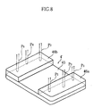
- the check plate 4' has a base member 45 and two conducting portions 46a, 46b.
- the base member 45 is formed into a rectangular shape from a material with highly insulating properties (for example, a resistance value of 10 11 ⁇ or higher).
- Each of the conducting portions 46a, 46b is positioned at a short edge of the base member 45. Hence the conducting portions 46a, 46b are insulated from each other.
- This check plate 4' is formed such that the plane-view area of the base member 45 corresponds to the area of the bottom face 31 of the set portion 3 (see Figs. 1 and 2) of the analyzer X1, and the total thickness of the base member 45 and the conducting portions 46a, 46b corresponds to the thickness of the set portion 3.
- the check plate 4' is entirely accommodated by the set portion 3.
- the check plate 4' is set in the set portion 3 with the conducting portions 46a, 46b on the lower side, the conducting portions 46a, 46b each are in contact with the probes P 1 to P 6 .
- the probes P 1 , P 3 , P 5 , and the probes P 2 , P 4 , P 6 are respectively electrically connected, and the potential difference measurement circuit 6 is configured as shown in Fig. 9.
- the probe P 3 for input to the Cl - measurement circuit 61 is grounded, and by turning on the analog switch S 5 , power from the power supply 64 is supplied to the probe P 4 .
- three types of standard voltages +100 mV, 0V, and -100 mV, can be supplied to the probe P 4 from the power supply 64. Consequently the potential difference measurement circuit 6 can be tested using three types of standard voltage.
- three types of voltage can be supplied directly to the A/D converter 63a from the power supply 64.
- Tests using +100 mV are performed with the switch S 6 connected to the +100 mV terminal. First only the analog switch S 4 is closed, and the value is measured using the A/D converter 63a. If the measured value deviates from +100 mV, the knob-operated regulator 63b is used to calibrate the A/D converter 63a such that the measurement value is +100 mV.
- the analog switch S 4 is opened, and the analog switch S 5 is closed.
- the probes P 2 , P 4 , P 6 are shunted via the conducting portion 46b, so that the voltage from the power supply 64 is input, via the probe P 4 , to the K + measurement circuit 60 and the Na + measurement circuit 62 from the probes P 2 , P 6 .
- the input from the probe P 2 is input to the impedance-matching amplifier 60Aa of the impedance-matching system 60A and is amplified.
- zero voltage is input to the impedance-matching amplifier 60Ab through the probe P 1 shunted to the grounded probe P 3 , and is amplified.
- the outputs from the impedance-matching amplifiers 60Aa, 60Ab are differentiated by the differentiating system 60B, and a level equivalent to the input difference (potential difference) is output.
- the output from the differentiating system 60B is subjected to noise reduction via the low-pass filter 60C, and is output from the low-pass filter 60C.
- the output from the low-pass filter 60C is measured by the A/D converter 63a.
- the A/D converter 63a has previously been calibrated to +100 mV, and a voltage of +100 mV is applied across the probes P 1 , P 2 .
- the value measured by the A/D converter 63a is +100 mV.
- the value measured by the potential difference measurement instrument 63 is shifted upward a fixed amount from +100 mV, then either there is an abnormality in the K + measurement circuit 60, or else contact failure between the probes P 1 to P 4 and the check plate 4' has occurred.
- the analog switch S 3 is closed and the analog switches S 1 , S 2 , S 4 are opened, then an test can be performed to determine, from the measured value of the A/D converter 63a, whether there is a defect in the Na + measurement circuit 62, or whether contact failure occurs at the probes P 3 to P 6 .
- the Cl - measurement circuit 61 is tested via the check plate 4' by closing the analog switches S 2 , S 5 and opening the analog switches S 1 , S 3 , S 4 .
- the potential difference measurement instrument 63 has already been calibrated at +100 mV in the test of the K + measurement circuit 60, and so there is no need to repeat this calibration in tests of the Na + measurement circuit 62 and the Cl - measurement circuit 61.
- tests are performed at 0V and at -100mV. These tests are substantially similar to the test at +100 mV explained.
- the analog switches S 1 to S 6 are switched appropriately, and test of the K + measurement circuit 60, test of the Na + measurement circuit 62, and test of the Cl - measurement circuit 61 are performed in sequence.
- the analyzer X2 shown in Fig. 10 computes the concentration of a specific component in a sample liquid from the value of the current flowing when a constant voltage is applied.
- the sample liquid may be, for example, blood or other biological samples, or liquids obtained by adjusting same.
- Specific components may be, for example, glucose or cholesterol.
- the analyzer X2 comprises an operating button 70, and a display 71 to display measurement results, as shown in Figs. 10 and 11.
- This analyzer X2 has a response current measurement circuit 72, set portion 73, computation portion 74, and determination portion 75.
- the response current measurement circuit 72 has a constant voltage supply portion 76, constant current supply portion 77, amplifier portion 78, and current value measurement instrument 79.
- the constant voltage supply portion 76 provides a constant voltage to the biosensor 8 during measurements of the concentration of the specific component.
- the constant current supply portion 77 supplies a constant current to the test piece 8' (see Fig. 14) during test of the response current measurement circuit 72.
- the state in which the constant voltage supply portion 76 or constant current supply portion 77 is connected to the biosensor 8 or test piece 8' is selected by turning the analog switch S on and off.
- the analog switch S can also select the state in which the test piece 8' is grounded. Hence by switching the analog switch, a plurality of standard currents can be supplied to the test piece 8'.
- the current value measurement instrument 79 has, for example, an A/D converter 79a capable of current measurements, and a knob-operated regulator 79b which performs calibration of the A/D converter 79a.
- the set portion 73 is the location in which the biosensor 8 is installed as the test piece. This set portion 73 is provided with measurement probes 73a, 73b to make contact with the terminal portions 86b, 87b of the biosensor 8.
- the computation portion 74 computes the concentration of the specific component based on the current value measured by the A/D converter 79a.
- This computation portion 74 has, for example, a CPU, ROM, and RAM.
- Working curve data indicating the relation between the concentration of each specific component and the response current value, and a program to compute the concentration of a specific component by applying measured current values to the working curve data, are stored in the ROM.
- the determination portion 75 judges whether there is a defect in the potential difference measurement circuit 6.
- the determination portion 75 has, for example, a CPU, ROM, and RAM.
- the ROM stores, for example, ideal response current values for each standard current, and a program which compares response current values actually measured by the A/D converter 79a for each standard current, and judges whether there is a defect in the response current measurement circuit 72.
- the computation portion 74 and determination portion 75 may be configured so as to share the CPU and RAM.
- the biosensor 8 has a cover plate 80, spacer 81, and base 82 in a stacked configuration.
- the cover plate 80 is provided with a hole 83.
- the spacer 81 is provided with a narrow slit 84, the tip of which is open.
- This slit 84 is linked with the hole 83.
- a passage 85 between the cover plate 80 and base 82 is formed.
- This passage 85 is linked with the exterior via the open tip portion 84a of the slit 84 and the hole 83.
- the open tip portion 84a is an opening for the introduction of sample liquid; the hole 83 is a vent hole to vent gas in the passage 85.
- a sample liquid supplied from the introductory opening (open tip portion) 84a proceeds through the passage 85 toward the hole (vent hole) by means of the capillary action effect.
- a pair of electrodes 86, 87 and a reaction portion 88 are provided on the upper face 82a of the base 82.
- the electrodes 86, 87 are covered by an insulating film 89 such that tips at one end 86a, 87a and tips at the other end 86b, 87b are exposed.
- the tip at one end 86a of the electrode 86 is a rectangular pad exposing a rectangular area.
- the tip at one end 87a of the electrode 87 is a "U"-shaped pad with a "U"-shaped area exposed, surrounding three sides of the rectangular pad 86a.
- the other tips 86b, 87b of these electrodes 86, 87 are terminal portions which are electrically connected to the measurement terminals 73a, 73b of the analyzer X2.
- the reaction portion 88 is, for example, a solid shape, provided so as to bridge the interval between the rectangular pad 86a and the "U"-shaped pad 87a.
- This reaction portion 88 comprises, for example, an oxidation-reduction enzyme and an electron acceptor.
- the oxidation-reduction enzyme for example, glucose oxidase, which oxidizes glucose in the blood to gluconic acid and reduces electron acceptors, is used.
- potassium ferricyanide is for example used as the electron acceptor.
- the biosensor 8 is set in the set portion 73 of the analyzer X2, and the terminal portions 86b, 87b are electrically connected with the measurement probes 73a, 73b of the analyzer X2.
- a sample liquid introduced from the introductory opening 84a of the biosensor 8 proceeds within the passage 85 through capillary action.
- the sample liquid dissolves the reaction portion 88.
- electrons are removed from the specific component in the sample by the oxidation-reduction enzyme, the specific component is oxidized, and the electrons are supplied to the electron acceptor, thereby reducing the electron acceptor.
- a constant voltage is applied by the constant voltage supply portion 76 (see Fig. 11) across the terminal portions 86a, 87a after a fixed amount of time from the introduction of the sample liquid, electrons accepted by the electron acceptor are emitted from the electron acceptor.
- the concentration of the specific component is computed by the computation portion 74 from the measured current value.
- the computation result is, for example, displayed on the display 71 (see Fig. 10).
- the response current measurement circuit 72 can be tested. In this test, damage to the electronic components and breakage of wiring comprised by the response current measurement circuit 72, as well as contract failure between measurement probes 73a, 73b and the check piece 8' (biosensor 8), can be investigated.
- the check plate 8' has a conductor 88', for example, positioned to correspond to the reaction portion 88 of the biosensor 8. Hence with the check plate 8' set in the set portion 73 of the analyzer X2, the response current measurement circuit 72 becomes the circuit shown in Fig. 14.
- the analog switch S is switched to connect the terminal portion 87b of the check piece 8' with the constant current supply portion 77, in order to supply a constant current (standard current) to the check piece 8'.
- the standard current value is, for example, 10 ⁇ A.
- the output from the check piece 8' is amplified by the amplifier portion 78 and is then input to the current value measurement instrument 79.
- the response current value is measured by the A/D converter 79a.
- the response current value measured by the A/D converter 79a is compared with the ideal response current value obtained when a standard current is supplied to the check piece 8', to judge whether the response current measurement circuit 72 is normal or not.
- the response current measurement circuit 72 is configured such that, ideally, the standard current supplied to the check piece 8' is measured by the A/D converter 79a. Hence when the response current value measured by the A/D converter 79a deviates from the standard current, exceeding a tolerance range, the determination portion 75 judges that an abnormality has occurred in the response current measurement circuit 72.
- the analog switch S is switched to ground the terminal portion 87b of the check piece 8', setting the standard current value to zero.
- the determination portion 75 judges that an abnormality has occurred in the response current measurement circuit 72.
- the determination portion 75 judges that the response current measurement circuit 72 is normal.
- the current value measurement instrument 79 may be connected to the constant current supply portion 77, and the knob-operated regulator 79b used to calibrate the A/D converter 79a, after which response current values are measured.
- tests of the measurement electrical circuits 6, 72 are performed based on a plurality of electrical conditions, as explained referring to Figs. 9 and 14. Even in cases in which a measurement of the response for a single electrical condition results in a small difference between the response and the electrical condition, so that a judgment of normality is not possible, if measurements are performed for a plurality of electrical conditions, a large difference with the response may appear for one of the electrical conditions. Hence if the responses for each of the electrical conditions are considered in combination, it is possible to perform tests for defects in the measurement electrical circuits 6, 72 with greater reliability.
- the linearity of a plot of the responses can provide a better understanding of whether the measurement precision is sufficient within the range of the plurality of electrical conditions.
- a step is included in which, prior to applying a standard voltage to the check plate 4', a standard voltage is applied to the A/D converter 63a to calibrate the A/D converter 63a.
- the potential difference measurement circuit 6 can be reliably tested for defects even if the standard voltage supplied to the check plate 4' is not the desired value, and even if error occurs in the measurement value of the A/D converter 63a.
- An analyzer of this invention may be configured such that, after a test piece set in the set portion has been drawn into the device, potential differences and current values are measured in the device interior.
- An analyzer of this invention may be configured such that a check plate is incorporated in advance into the interior of the analyzer, so that by selecting an test mode, tests of the measurement electrical circuit are performed automatically using the check plate.
- This invention places no limits in particular on the number or types of specific components to be measured by the analyzer.
Landscapes
- Chemical & Material Sciences (AREA)
- Life Sciences & Earth Sciences (AREA)
- Health & Medical Sciences (AREA)
- Physics & Mathematics (AREA)
- Chemical Kinetics & Catalysis (AREA)
- Electrochemistry (AREA)
- Molecular Biology (AREA)
- Analytical Chemistry (AREA)
- Biochemistry (AREA)
- General Health & Medical Sciences (AREA)
- General Physics & Mathematics (AREA)
- Immunology (AREA)
- Pathology (AREA)
- Investigating Or Analyzing Materials By The Use Of Electric Means (AREA)
Abstract
Description
- This invention relates to a device for measuring the concentration of a specific component in a sample liquid, and a method of testing such a device.
- One method for measuring the concentration of a specific component in a sample liquid is a method in which the specific component concentration is computed from the potential difference arising when a reference liquid containing a known concentration of the specific component and a sample liquid containing an unknown concentration of the specific component are electrically shunted.
- In this method, by for example setting a plate for concentration measurement relative to the analyzer, the concentration of the specific component is measured. Below, the case in which the concentrations of three types of specific components (for example, K+, Na+, Cl-) in a sample liquid are measured is explained.
- The analyzer has, at least, a set portion in which a plate for concentration measurement is set; three pairs of probes (for a total of six); and computation means to compute the concentration of the specific component from the potential differences between each pair of probes.
- The plate for concentration measurement has, at least, a reference liquid reception portion, onto which reference liquid is spot-applied; a reference liquid holding portion, which holds the reference liquid; first through third terminal portions, which are in electrical contact with the reference liquid of the reference liquid holding portion; a sample liquid reception portion, into which the sample liquid is spot-applied; a sample liquid holding portion, which holds the sample liquid; fourth through sixth terminal portions, which are in electrical contact with the sample liquid holding portion; and a bridge, which electrically shunts the reference liquid of the reference liquid holding portion and the sample liquid of the sample liquid holding portion.
- When the concentration measurement plate is set in the set area of the analyzer, the corresponding probe of the analyzer is in contact with each of the terminal portions. In the analyzer, potential differences between the reference liquid and sample liquid are measured for each specific component, via each probe pair. The computation means of the analyzer computes the concentrations of each specific component based on the potential difference measurement results.
- In this analyzer, instead of a concentration measurement plate, a check plate is set in the set portion, and the potential difference measurement electrical circuit is tested for defects. Causes of electrical circuit defects include, for example, malfunctions of electronic parts, breakage in wiring, and contact failure between a probe and the concentration measurement plate (first through sixth terminal portion).
- A method of test of the electrical circuit for potential difference measurement is described in, for example, JP-B 6-82113 and in JP-B 7-111409.
- The test method described in JP-B 6-82113 employs
check plates 9A to 9D, as shown in Figs. 15 to 18 of this application. Each of thesecheck plates 9A to 9D has abase plate 90 in which are provided a total of six through-holes 90a corresponding to three pairs of probes in the analyzer. On thebase plate 90 is stacked acover plate 92, enclosing conductinglayers 91a to 91d. Various configurations for the conductinglayers 91a to 91d are shown in Figs. 15 to 18. - Each of these
check plates 9A to 9D is set in the analyzer similarly to a test plate. At this time, each of the probes is in contact with theconducting layers 91a to 91d, so that each of the probe pairs is shunted. Test of the electrical circuit for potential difference measurement is performed by measuring the potential differences between the probe pairs. In this test method, if the potential difference between each probe pair is zero, the electrical circuit for potential difference measurement of the analyzer is judged to be normal, and if not zero, the circuit is judged to be abnormal. - In this test method, measured potentials are always zero, so that it is not possible to test reliably for the presence of defects in the electrical circuit for potential difference measurement. For example, even in a case in which a measurement value corresponding to the actual potential difference cannot be observed due to some abnormality, the measured value for the zero potential in tests is measured as either zero or as a value close to zero. In this case, it is judged that there is no abnormality in the electrical circuit for potential difference measurements. It is also difficult to determine the measurement precision for potentials which deviate greatly from zero potential.
- On the other hand, in the test method described in JP-B 7-111409, a
check plate 9E such as shown in Fig. 19 is used. Thischeck plate 9E has abase plate 90 in which are provided a total of six through-holes 90a corresponding to the three probe pairs of the analyzer. On thisbase plate 90 are placed six conductingpads 91e which separately cover each of the through-holes 90a. These conductingpads 91e, together with resistors R1 to R3 and abattery 91f, constitute an electrical circuit as shown in Fig. 20. The conductingpads 91e, resistors R1 to R3, andbattery 91f are enclosed by theframe 92 positioned on thebase plate 90. The space enclosed by theframe 92 is sealed with resin. - With the probes brought into contact with the
conducting pads 91e in thecheck plate 9E, a voltage is applied across each of the probe pairs by thebattery 91f. The voltage value for each probe pair is measured, and the electrical circuit for potential difference measurement is tested for defects. - In this test method, a voltage is applied to each of the probe pairs by the
battery 91f incorporated into thecheck plate 9E, so that the precision of the output of thebattery 91f necessarily has an effect on the test results. The battery output is not strictly constant; in particular, if consumption exceeds a certain capacity, the output gradually declines. Hence a method which employs abattery 91f cannot be regarded as appropriate in order to maintain test precision. Moreover, it is difficult to make the output of thebattery 91f incorporated into thecheck plate 9E variable. Consequently a givencheck plate 9E can only perform tests using a single reference potential, and so there is the drawback that, similarly to test methods described in the previous publications, defects in an electrical circuit for potential difference measurement cannot be reliably detected. - A first aspect of this invention provides an analyzer for measuring a concentration of a specific component in a sample liquid supplied to the test piece with use of a test piece which has a first terminal portion and a second terminal portion, the analyzer comprising a set portion in which the test piece is set, a first measurement terminal for electrical connection to the first terminal portion and a second measurement terminal for electrical connection to the second terminal portion, and a measurement electrical circuit to measure parameters necessary to compute the concentration of the specific component; the analyzer further comprising test means to test the measurement electrical circuit using a check piece instead of the test piece; wherein the test means applying a plurality of electrical conditions to the check piece for testing the measurement electrical circuit based on a plurality of electrical responses obtained from the measurement electrical circuit when the electrical conditions are applied individually.
- In a preferred embodiment, the test means is designed to test the measurement electrical circuit by comparing each of the electrical responses with an ideal electrical response for each of the electrical conditions.
- In a preferred embodiment, the analyzer is designed to measure the potential difference occurring between a reference liquid having a known concentration of the specific component, and a sample liquid having an unknown concentration of the specific component.
- In this case, the check piece used has a first conducting portion for contact with the first measurement terminal and a second conducting portion for contact with the second measurement terminal. When the check piece is not set in the set portion, the first conducting portion and the second conducting portion are insulated from each other.
- As the plurality of electrical conditions, for example, a plurality of standard voltages are set. The plurality of standard voltages are, for example, at least two voltages selected from among positive values, zero, and negative values.
- It is preferable that at least one among the plurality of standard voltages be applied by supplying a voltage from the power supply to the first conducting portion, while grounding the second conducting portion. The voltage of the power supply is, for example, controlled using a regulator within the analyzer.
- In a preferred embodiment, the measurement electrical circuit is designed such that the current value is measured when a constant voltage is applied across the first terminal portion and the second terminal portion.
- In this case, the check piece used has a first conducting portion for contact with the first measurement terminal and a second conducting portion for contact with the second measurement terminal. The first conducting portion and the second conducting portion are electrically connected.
- As the plurality of electrical conditions, for example, a plurality of standard currents are set. The plurality of standard currents include, for example, positive values and zero.
- In a preferred embodiment, the measurement electrical circuit has a response measurement instrument which measures the electrical response, and is designed to apply an electrical condition to the response measurement instrument and calibrate the response measurement instrument.
- When testing the measurement electrical circuit, the check plate may be incorporated from outside the device, or may be incorporated into the device interior in advance.
- A second aspect of this invention provides a method of testing an analyzer for measuring a concentration of a specific component in a sample liquid supplied to a test piece having a first terminal portion and a second terminal portion; the analyzer comprising a set portion in which the test piece is set, a first measurement terminal for electrical connection to the first terminal portion, a second measurement terminal for electrical connection to the second terminal portion, and a measurement electrical circuit which measures parameters necessary to compute the concentration of the specific component, the method comprising: a first step for applying an electrical condition to the check piece; a second step for measuring an electrical response obtained from the measurement electrical circuit when the electrical condition is applied; and a third step for comparing the electrical response with an ideal electrical response obtainable when the electrical condition is applied to the check piece; wherein the first through third steps are performed separately for each of a plurality of electrical conditions.
- In a preferred embodiment, the measurement electrical circuit has a response measurement instrument to measure the electrical response, and a step is included in which, prior to the first step, an electrical condition is applied to the response measurement instrument, and the response measurement instrument is calibrated.
- As the plurality of electrical conditions, a plurality of standard voltages, or a plurality of standard currents, are set.
-
- Fig. 1 is an overall perspective view showing one example of an analyzer of a first embodiment of the invention.
- Fig. 2 is an enlarged perspective view of principal components, showing the configuration in the vicinity of the pipette holder in the analyzer of Fig. 1.
- Fig. 3 is an enlarged perspective view of principal components, showing the configuration in the vicinity of the set portion in which the potential difference measurement plate (test piece) is set in the analyzer of Fig. 1.
- Fig. 4 is an overall perspective view, seen from the top surface side, of a potential difference measurement plate.
- Fig. 5 is an overall perspective view, seen from the rear surface side, of a potential difference measurement plate.
- Fig. 6 is an exploded perspective view of a potential difference measurement plate.
- Fig. 7 is a schematic view showing mainly the potential difference measurement circuit, when the potential difference measurement plate of Fig. 4 through Fig. 6 is set in the analyzer of Fig. 1.
- Fig. 8 is an overall perspective view of a check plate (check piece) used when testing a potential difference measurement circuit.
- Fig. 9 is a schematic view mainly showing a potential difference measurement circuit when a check plate is set in the analyzer of Fig. 1.
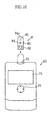
- Fig. 10 is a front view showing one example of an analyzer and biosensor (test piece) of a second embodiment of this invention.
- Fig. 11 is a schematic view mainly showing a circuit for response current measurement, when a biosensor is set in the analyzer of Fig. 10.
- Fig. 12 is an overall perspective view showing one example of a biosensor.
- Fig. 13 is an exploded perspective view of the biosensor of Fig. 12.
- Fig. 14 is a schematic view mainly showing a circuit for response current measurement, when a check piece is set in the analyzer.
- Fig. 15 is an exploded perspective view showing one example of a conventional check piece.
- Fig. 16 is an exploded perspective view showing another example of a conventional check piece.
- Fig. 17 is an exploded perspective view showing another example of a conventional check piece.
- Fig. 18 is an exploded perspective view showing another example of a conventional check piece.
- Fig. 19 is an exploded perspective view showing another example of a conventional check piece.
- Fig. 20 is a circuit diagram of the check piece of Fig. 19.
- The analyzer X1 of a first embodiment of this invention, shown in Fig. 1, electrochemically measures the concentration of a specific component in a sample liquid through comparison with a reference liquid containing a known concentration of the specific component.
- The sample liquid may be, for example, blood, urine, saliva, or other biological samples, or liquids obtained by adjusting same. Specific components may be, for example, Na+, K+, or Cl-.
- On the upper face of the analyzer X1 are provided
various operation buttons 10, adisplay 11 which displays measurement results and operating conditions, and adischarge portion 12 which discharges recording paper K. On the front face of the analyzer X1 is provided apipette holder 2. On the bottom of thepipette holder 2 is provided aset portion 3, in which is set a potential difference measurement plate 4 (see Fig. 4 through Fig. 6). - The
pipette holder 2 has afirst space 20 which is penetrated vertically and open in the forward direction, and asecond space 21 which is connected with thefirst space 20 below thefirst space 20, and is open in the forward direction, as shown in Fig. 1 and Fig. 2. Thebody portion 50 of the pipette 5 is accommodated by thefirst space 20, and thetip portions second space 21. Astep 22 is formed between thefirst space 20 andsecond space 21. Thebottom face 52 of thebody portion 50 of the pipette 5 catches on theupper face 22a of thisstep 22. - The pipette 5 shown in Fig. 2 is a double pipette. In this pipette 5, by moving the operating
portions - The set
portion 3 has anaccommodating space 30 capable of holding a potential difference measurement plate 4 (see Fig. 4 through Fig. 6), as shown in Fig. 3. Three pairs (for a total of six) of probes P1 through P6 protrude upward from thebottom face 31 of thisset portion 3. In the analyzer X1, the potential differences arising from differences in concentration of, for example, K+, Na+, or Cl- between a reference liquid and a sample liquid are measured through these probe pairs P1 to P6. - The potential
difference measurement plate 4 is formed by stacking a resistlayer 41 andcover film 42 onto abase film 40, as shown in Fig. 4 through Fig. 6. The potentialdifference measurement plate 4 is configured so as to enable measurement of potential differences for three types of ions, for example Na+, K+, and Cl-. - The
base film layer 40 is electrically insulating. Thebase film layer 40 has a rectangular shape overall. - Three terminals each, 40A to 40C and 40D to 40F, are formed on the two short edges of the
base film layer 40. Each of the three sets ofterminals 40A to 40C and 40D to 40F is arranged in the direction of the shorter edges of thebase film layer 40. Through-holes terminals 40A to 40F at the two shorter edges of thebase film layer 40. By means of the through-holes 40G to 40L, the correspondingterminals 40A to 40F are exposed. The probes P1 to P6 are in contact with theterminals 40A to 40F via the corresponding through-holes 40G to 40L. - Six liquid-receiving
pads 40a to 40f are formed in the center portion of thebase film layer 40. Specific components of the reference liquid or sample liquid are supplied to these liquid-receivingpads 40a to 40f. Each of the liquid-receivingpads 40a to 40f is electrically connected to thecorresponding terminals 40A to 40F via the conducting wires 40Aa, 40Bb, 40Cc, 40Dd, 40Ee, 40Ff. - The resist
film layer 41 comprises a first resistfilm layer 43, and a second resistfilm layer 44. The first resistfilm layer 43 and second resistfilm layer 44 are electrically insulating. The first resistfilm layer 43 and second resistfilm layer 44 have a rectangular shape overall. - Six connecting
holes 44a to 44f are formed in the center portion of the second resistfilm layer 44. Anion selection film 45a to 45f is inserted into each of the connectingholes 44a to 44f. Theion selection films ion selection films ion selection films - A reference
liquid holding hole 43g and sampleliquid holding hole 43h are formed in the center portion of the first resistfilm 43. The referenceliquid holding hole 43g is connected to the three connectingholes liquid holding hole 43h is connected to the three connectingholes liquid holding hole 43g and sampleliquid holding hole 43h are connected via acutout 43i. Abridge 45i permitting the movement of ions is positioned in thiscutout 43i. - A reference
liquid receiving aperture 42g and sampleliquid receiving aperture 42h are formed in the center portion of the long side of thecover film layer 42. The referenceliquid receiving aperture 42g is connected to the referenceliquid holding hole 43g of the first resistfilm layer 43. The sampleliquid receiving aperture 42h is connected to the sampleliquid holding hole 43h of the first resistfilm 43. Twoair vent holes 42j are formed in thecover film layer 42. Each of theair vent holes 42j is connected to both the referenceliquid holding hole 43g and to the sampleliquid holding hole 43h. - In actual potential difference measurements, as shown in Fig. 2, first the potential
difference measurement plate 4 is set in theset portion 3, and a pipette 5 is held by thepipette holder 2. - The potential difference measurement plate 6 is set such that the reference
liquid receiving aperture 42g and sampleliquid receiving aperture 42h are opened upward. In this state, theterminals 40A to 40F of the potentialdifference measurement plate 4 are in contact with the corresponding probes P1 to P6, as shown in Fig. 5. - On the other hand, tips Ta, Tb are mounted on the
tip portions portions pipette holder 2 by catching thebottom face 52 of thebody portion 50 on theupper face 22a of thestep 22 of thepipette holder 2. - Next, the operating
portions liquid receiving aperture 42g, and the sample liquid is spot-applied to the sampleliquid receiving aperture 42h. - As is clear from Fig. 6, the reference liquid R which is spot-applied from the reference
liquid receiving aperture 42g is held by the referenceliquid holding hole 43g, and the sample liquid S which is spot-applied from the sampleliquid receiving aperture 42h is held by the sampleliquid holding hole 43h. Because the referenceliquid holding hole 43g and sampleliquid holding hole 43h are connected via acutout 43i in which abridge 45i is positioned, the reference liquid R and sample liquid S are electrically shunted. - The K+, Cl- and Na+ ions in the reference liquid R held in the reference
liquid holding hole 43g pass through theion selection membranes pads liquid holding hole 43h pass through theion selection membranes pads pads pads - This potential difference is measured by the potential difference measurement electrical circuit 6 shown in Fig. 7, via the three pairs of probes P1 to P6. As shown in Fig. 5, the potential difference arising from the difference in concentration of K+ is measured by bringing the probes P1, P2 into contact with the
terminals terminals terminals - As shown in Fig. 7, the potential difference measurement circuit 6 has a K+ measurement circuit 60, Cl- measurement circuit 61, Na+ measurement circuit 62, potential
difference measurement instrument 63,power supply 64,computation portion 65,determination portion 66, and a plurality of analog switches S1 to S6. - The K+ measurement circuit 60, Cl- measurement circuit 61, and Na+ measurement circuit 62 have an impedance-matching
system differential system pass filter - The impedance-matching
systems system 61A has a single impedance-matchingamplifier 61a. - The
differential systems differential amplifiers systems amplifier 61a in the impedance-matchingsystem 61A, one of the inputs to thedifferential amplifier 61b is zero. - The low-
pass filters - The potential
difference measurement instrument 63 has, for example, an A/D converter 63a capable of potential difference measurement, and a knob-operatedregulator 63b which calibrates this A/D converter 63a. - The voltage of the
power supply 64 is controlled by a regulator within the equipment. Thispower supply 64 is designed to be able to supply three types of voltage (standard voltages), 100 mV, 0 mV, and -100 mV, to the probe P4 by switching an analog switch S6. - The
computation portion 65 computes the concentration of a specific component based on the potential difference measured by the A/D converter 63a. Thiscomputation portion 65 has, for example, a CPU, ROM, and RAM. Working curve data indicating the relation between the concentration of each specific component and the potential difference, and a program to compute the concentration of a specific component by applying measured potential differences to the working curve data, are stored in the ROM. The working curve data is created based on, for example, the Nernst equation. - The
determination portion 66 judges whether there is a defect in the potential difference measurement circuit 6. Thisdetermination portion 66 has, for example, a CPU, ROM, and RAM. Ideal response voltage values for each standard voltage, and a program which compares response voltage values actually measured by the A/D converter 63a at each standard voltage and judges whether there is a defect in the potential difference measurement circuit 6, for example, are stored in the ROM. - The
computation portion 65 anddetermination portion 66 may be configured so as to share the CPU and RAM. - Each of the
measurement circuits - In the potential difference measurement circuit 6, potential difference measurements for K+, Cl-, or Na+ are performed as follows.
- First, the analog switch S1 is closed, and the analog switches S2, S3, S4, and S5 are opened. In this state, the output from the probes P1, P2 is input to each of the amplifiers 60Aa, 60Ab of the impedance-matching
system 60A, and is amplified. The outputs from the amplifiers 60Aa, 60Ab are differentiated by the differentiatingamplifier 60b. This difference is equivalent to the difference in inputs (potential difference) from the probes P1, P2. The potential difference is measured in the potentialdifference measurement instrument 63 after passing through the low-pass filter 60C. - Similarly, by closing the analog switch S2 while opening the analog switches S1, S3, S4, S5, the potential difference equivalent to the input difference between the probes P3, P4 is measured in the potential
difference measurement instrument 63. The input difference (potential difference) between the probes P5, P6 is measured in the potentialdifference measurement instrument 63 by closing only the analog switch S3. - The concentrations of specific components are computed by the
computation portion 65 from the potential difference measurement results. The computation results are displayed, for example, on thedisplay 11. The computation results can be printed onto recording paper K discharged from thedischarge portion 12 by operation of an appropriate operating button (see Fig. 1). Of course, the measurement results can also be recorded onto an IC card, floppy disk, or other recording media. - By using the check plate 4' shown in Fig. 8 in the analyzer X1, the potential difference measurement circuit 6 can be tested for defects. Possible defects in the potential difference measurement circuit 6 include damage to electronic components comprised by the circuit; wire breakage; and contact failure of the probes P1 to P6 with the check plate 4' (potential measurement plate 4).
- The check plate 4' has a
base member 45 and two conductingportions base member 45 is formed into a rectangular shape from a material with highly insulating properties (for example, a resistance value of 1011 Ω or higher). Each of the conductingportions base member 45. Hence the conductingportions - This check plate 4' is formed such that the plane-view area of the
base member 45 corresponds to the area of thebottom face 31 of the set portion 3 (see Figs. 1 and 2) of the analyzer X1, and the total thickness of thebase member 45 and the conductingportions portion 3. Hence similarly to the case of the potentialdifference measurement plate 4, the check plate 4' is entirely accommodated by the setportion 3. At this time, if the check plate 4' is set in theset portion 3 with the conductingportions portions - In the potential difference measurement circuit 6, the probe P3 for input to the Cl- measurement circuit 61 is grounded, and by turning on the analog switch S5, power from the
power supply 64 is supplied to the probe P4. As explained, three types of standard voltages, +100 mV, 0V, and -100 mV, can be supplied to the probe P4 from thepower supply 64. Consequently the potential difference measurement circuit 6 can be tested using three types of standard voltage. Also, by turning off the analog switches S4, S5, three types of voltage can be supplied directly to the A/D converter 63a from thepower supply 64. - Tests using +100 mV are performed with the switch S6 connected to the +100 mV terminal. First only the analog switch S4 is closed, and the value is measured using the A/
D converter 63a. If the measured value deviates from +100 mV, the knob-operatedregulator 63b is used to calibrate the A/D converter 63a such that the measurement value is +100 mV. - Next, the analog switch S4 is opened, and the analog switch S5 is closed. The probes P2, P4, P6 are shunted via the conducting
portion 46b, so that the voltage from thepower supply 64 is input, via the probe P4, to the K+ measurement circuit 60 and the Na+ measurement circuit 62 from the probes P2, P6. - If the analog switch S1 is closed and the analog switches S2, S3 are opened, the input from the probe P2 is input to the impedance-matching amplifier 60Aa of the impedance-matching
system 60A and is amplified. On the other hand, zero voltage is input to the impedance-matching amplifier 60Ab through the probe P1 shunted to the grounded probe P3, and is amplified. The outputs from the impedance-matching amplifiers 60Aa, 60Ab are differentiated by the differentiatingsystem 60B, and a level equivalent to the input difference (potential difference) is output. The output from the differentiatingsystem 60B is subjected to noise reduction via the low-pass filter 60C, and is output from the low-pass filter 60C. The output from the low-pass filter 60C is measured by the A/D converter 63a. - The A/
D converter 63a has previously been calibrated to +100 mV, and a voltage of +100 mV is applied across the probes P1, P2. Hence if the K+ measurement circuit 60 is normal, and there is no contact failure between the probes P1 to P4 and the check plate 4', the value measured by the A/D converter 63a is +100 mV. On the other hand, if the value measured by the potentialdifference measurement instrument 63 is shifted upward a fixed amount from +100 mV, then either there is an abnormality in the K+ measurement circuit 60, or else contact failure between the probes P1 to P4 and the check plate 4' has occurred. - If the analog switch S3 is closed and the analog switches S1, S2, S4 are opened, then an test can be performed to determine, from the measured value of the A/
D converter 63a, whether there is a defect in the Na+ measurement circuit 62, or whether contact failure occurs at the probes P3 to P6. On the other hand, the Cl- measurement circuit 61 is tested via the check plate 4' by closing the analog switches S2, S5 and opening the analog switches S1, S3, S4. - The potential
difference measurement instrument 63 has already been calibrated at +100 mV in the test of the K+ measurement circuit 60, and so there is no need to repeat this calibration in tests of the Na+ measurement circuit 62 and the Cl- measurement circuit 61. - Then, tests are performed at 0V and at -100mV. These tests are substantially similar to the test at +100 mV explained. For example, after performing calibration of the potential
difference measurement instrument 63, the analog switches S1 to S6 are switched appropriately, and test of the K+ measurement circuit 60, test of the Na+ measurement circuit 62, and test of the Cl- measurement circuit 61 are performed in sequence. - Next, the analyzer of a second embodiment of the invention is explained, referring to Fig. 10 through Fig. 14.
- The analyzer X2 shown in Fig. 10 computes the concentration of a specific component in a sample liquid from the value of the current flowing when a constant voltage is applied.
- The sample liquid may be, for example, blood or other biological samples, or liquids obtained by adjusting same. Specific components may be, for example, glucose or cholesterol.
- The analyzer X2 comprises an
operating button 70, and adisplay 71 to display measurement results, as shown in Figs. 10 and 11. This analyzer X2 has a responsecurrent measurement circuit 72, setportion 73,computation portion 74, anddetermination portion 75. - The response
current measurement circuit 72 has a constantvoltage supply portion 76, constantcurrent supply portion 77,amplifier portion 78, and currentvalue measurement instrument 79. - The constant
voltage supply portion 76 provides a constant voltage to thebiosensor 8 during measurements of the concentration of the specific component. The constantcurrent supply portion 77 supplies a constant current to the test piece 8' (see Fig. 14) during test of the responsecurrent measurement circuit 72. The state in which the constantvoltage supply portion 76 or constantcurrent supply portion 77 is connected to thebiosensor 8 or test piece 8' is selected by turning the analog switch S on and off. The analog switch S can also select the state in which the test piece 8' is grounded. Hence by switching the analog switch, a plurality of standard currents can be supplied to the test piece 8'. - The current
value measurement instrument 79 has, for example, an A/D converter 79a capable of current measurements, and a knob-operatedregulator 79b which performs calibration of the A/D converter 79a. - The set
portion 73 is the location in which thebiosensor 8 is installed as the test piece. This setportion 73 is provided withmeasurement probes terminal portions biosensor 8. - The
computation portion 74 computes the concentration of the specific component based on the current value measured by the A/D converter 79a. Thiscomputation portion 74 has, for example, a CPU, ROM, and RAM. Working curve data indicating the relation between the concentration of each specific component and the response current value, and a program to compute the concentration of a specific component by applying measured current values to the working curve data, are stored in the ROM. - The
determination portion 75 judges whether there is a defect in the potential difference measurement circuit 6. Thedetermination portion 75 has, for example, a CPU, ROM, and RAM. The ROM stores, for example, ideal response current values for each standard current, and a program which compares response current values actually measured by the A/D converter 79a for each standard current, and judges whether there is a defect in the responsecurrent measurement circuit 72. - The
computation portion 74 anddetermination portion 75 may be configured so as to share the CPU and RAM. - As clearly shown in Figs. 12 and 13, the
biosensor 8 has acover plate 80,spacer 81, andbase 82 in a stacked configuration. - The
cover plate 80 is provided with ahole 83. Thespacer 81 is provided with anarrow slit 84, the tip of which is open. This slit 84 is linked with thehole 83. By means of theslit 84, apassage 85 between thecover plate 80 andbase 82 is formed. Thispassage 85 is linked with the exterior via theopen tip portion 84a of theslit 84 and thehole 83. Theopen tip portion 84a is an opening for the introduction of sample liquid; thehole 83 is a vent hole to vent gas in thepassage 85. Hence a sample liquid supplied from the introductory opening (open tip portion) 84a proceeds through thepassage 85 toward the hole (vent hole) by means of the capillary action effect. - A pair of
electrodes reaction portion 88 are provided on theupper face 82a of thebase 82. - The
electrodes film 89 such that tips at oneend other end end 86a of theelectrode 86 is a rectangular pad exposing a rectangular area. The tip at oneend 87a of theelectrode 87 is a "U"-shaped pad with a "U"-shaped area exposed, surrounding three sides of therectangular pad 86a. On the other hand, theother tips electrodes measurement terminals - The
reaction portion 88 is, for example, a solid shape, provided so as to bridge the interval between therectangular pad 86a and the "U"-shapedpad 87a. Thisreaction portion 88 comprises, for example, an oxidation-reduction enzyme and an electron acceptor. As the oxidation-reduction enzyme, for example, glucose oxidase, which oxidizes glucose in the blood to gluconic acid and reduces electron acceptors, is used. On the other hand, potassium ferricyanide is for example used as the electron acceptor. - The
biosensor 8 is set in the setportion 73 of the analyzer X2, and theterminal portions - A sample liquid introduced from the
introductory opening 84a of thebiosensor 8 proceeds within thepassage 85 through capillary action. In this process, the sample liquid dissolves thereaction portion 88. At this time, electrons are removed from the specific component in the sample by the oxidation-reduction enzyme, the specific component is oxidized, and the electrons are supplied to the electron acceptor, thereby reducing the electron acceptor. If a constant voltage is applied by the constant voltage supply portion 76 (see Fig. 11) across theterminal portions - As shown in Fig. 11, electrons emitted from the electron acceptor (the output) are amplified by the
amplifier portion 78, and the result is input to the currentvalue measurement instrument 79. In this currentvalue measurement instrument 79, the response current value after, for example, a fixed length of time has elapsed from the start of application of the constant voltage is measured. - The concentration of the specific component is computed by the
computation portion 74 from the measured current value. The computation result is, for example, displayed on the display 71 (see Fig. 10). - In the analyzer X2, by setting a check piece 8' in the set
portion 73 in place of thebiosensor 8, as shown in Fig. 14, the responsecurrent measurement circuit 72 can be tested. In this test, damage to the electronic components and breakage of wiring comprised by the responsecurrent measurement circuit 72, as well as contract failure betweenmeasurement probes - The check plate 8' has a conductor 88', for example, positioned to correspond to the
reaction portion 88 of thebiosensor 8. Hence with the check plate 8' set in the setportion 73 of the analyzer X2, the responsecurrent measurement circuit 72 becomes the circuit shown in Fig. 14. - In tests of the response
current measurement circuit 72, the analog switch S is switched to connect theterminal portion 87b of the check piece 8' with the constantcurrent supply portion 77, in order to supply a constant current (standard current) to the check piece 8'. The standard current value is, for example, 10 µA. - The output from the check piece 8' is amplified by the
amplifier portion 78 and is then input to the currentvalue measurement instrument 79. In the currentvalue measurement instrument 79, the response current value is measured by the A/D converter 79a. - In the
determination portion 75, the response current value measured by the A/D converter 79a is compared with the ideal response current value obtained when a standard current is supplied to the check piece 8', to judge whether the responsecurrent measurement circuit 72 is normal or not. - The response
current measurement circuit 72 is configured such that, ideally, the standard current supplied to the check piece 8' is measured by the A/D converter 79a. Hence when the response current value measured by the A/D converter 79a deviates from the standard current, exceeding a tolerance range, thedetermination portion 75 judges that an abnormality has occurred in the responsecurrent measurement circuit 72. - Next, the analog switch S is switched to ground the
terminal portion 87b of the check piece 8', setting the standard current value to zero. At this time, if the response current value measured by the currentvalue measurement instrument 79 deviates greatly from zero, thedetermination portion 75 judges that an abnormality has occurred in the responsecurrent measurement circuit 72. - On the other hand, when two different standard currents are supplied to the check piece 8' and the response currents measured by the A/
D converter 79a agree, or substantially agree, with the corresponding standard currents, thedetermination portion 75 judges that the responsecurrent measurement circuit 72 is normal. - In the second embodiment of the invention also, the current
value measurement instrument 79 may be connected to the constantcurrent supply portion 77, and the knob-operatedregulator 79b used to calibrate the A/D converter 79a, after which response current values are measured. - In the analyzers X1, X2, rather than performing electrical tests of the measurement electrical circuit using a single standard voltage, as in the prior art, tests of the measurement
electrical circuits 6, 72 are performed based on a plurality of electrical conditions, as explained referring to Figs. 9 and 14. Even in cases in which a measurement of the response for a single electrical condition results in a small difference between the response and the electrical condition, so that a judgment of normality is not possible, if measurements are performed for a plurality of electrical conditions, a large difference with the response may appear for one of the electrical conditions. Hence if the responses for each of the electrical conditions are considered in combination, it is possible to perform tests for defects in the measurementelectrical circuits 6, 72 with greater reliability. - Further, if tests are performed for a plurality of electrical conditions, the linearity of a plot of the responses can provide a better understanding of whether the measurement precision is sufficient within the range of the plurality of electrical conditions.
- In the analyzer X1 of the first embodiment of this invention, as explained in reference to Fig. 9, a step is included in which, prior to applying a standard voltage to the check plate 4', a standard voltage is applied to the A/
D converter 63a to calibrate the A/D converter 63a. By performing this calibration, the potential difference measurement circuit 6 can be reliably tested for defects even if the standard voltage supplied to the check plate 4' is not the desired value, and even if error occurs in the measurement value of the A/D converter 63a. - An analyzer of this invention may be configured such that, after a test piece set in the set portion has been drawn into the device, potential differences and current values are measured in the device interior.
- An analyzer of this invention may be configured such that a check plate is incorporated in advance into the interior of the analyzer, so that by selecting an test mode, tests of the measurement electrical circuit are performed automatically using the check plate.
- It is sufficient to set a plurality of electrical conditions, without being limited to the three conditions +100 mV, 0V, -100 mV of the first embodiment of this invention, or to the
conditions 10 µA and 0A of the second embodiment of this invention. The number of electrical condition settings and the values of same are a matter of design. - This invention places no limits in particular on the number or types of specific components to be measured by the analyzer.
Claims (19)
- An analyzer for measuring a concentration of a specific component in a sample liquid supplied to the test piece with use of a test piece which has a first terminal portion and a second terminal portion, the analyzer comprising a set portion in which the test piece is set, a first measurement terminal for electrical connection to the first terminal portion and a second measurement terminal for electrical connection to the second terminal portion, and a measurement electrical circuit to measure parameters necessary to compute the concentration of the specific component;
the analyzer further comprising test means to test the measurement electrical circuit using a check piece instead of the test piece;
wherein the test means applying a plurality of electrical conditions to the check piece for testing the measurement electrical circuit based on a plurality of electrical responses obtained from the measurement electrical circuit when the electrical conditions are applied individually. - The analyzer according to claim 1, wherein the test means tests the measurement electrical circuit by comparing each of the electrical responses with ideal electrical responses for each of the electrical conditions.
- The analyzer according to claim 1, which is designed to measure a potential difference arising between a reference liquid having a known concentration of the specific component and the sample ' liquid having an unknown concentration of the specific component.
- The analyzer according to claim 3, wherein the check piece has a first conducting portion for contact with the first measurement terminal and a second conducting portion for contact with the second measurement terminal, the first conducting portion and the second conducting portion being electrically insulated from each other when the check piece is not set in the set portion.
- The analyzer according to claim 3, wherein a plurality of standard voltages are set as the plurality of electrical conditions.
- The analyzer according to claim 5, wherein the plurality of standard voltages are at least two selected from the group consisting of a positive value,. zero, and a negative value.
- The analyzer according to claim 6, wherein at least one of the plurality of standard voltages is applied by supplying the voltage from a power supply to the first conducting portion while grounding the second conducting portion.
- The analyzer according to claim 7, wherein the voltage of the power supply is controlled by a regulator within the device.
- The analyzer according to claim 1, wherein the measurement electrical circuit measures a current value when a constant voltage is applied across the first terminal portion and the second terminal portion.
- The analyzer according to claim 9, wherein the check piece has a first conducting portion for contact with the first measurement terminal and a second conducting portion for contact with the second measurement terminal, the first conducting portion and the second conducting portion being electrically connected.
- The analyzer according to claim 9, wherein a plurality of standard currents are set as the plurality of electrical conditions.
- The analyzer according to claim 11, wherein the plurality of standard currents includes a positive value and zero.
- The analyzer according to claim 1, wherein the measurement electrical circuit has a response measurement instrument to measure the electrical responses, the response measurement instrument being calibrated by applying electrical conditions to the response measurement instrument.
- The analyzer according to claim 1, wherein the check plate is incorporated into the device from outside the device at the time of performing tests of the measurement electrical circuit.
- The analyzer according to claim 1, wherein the check plate is incorporated into the device in advance.
- A method of testing an analyzer for measuring a concentration of a specific component in a sample liquid supplied to a test piece having a first terminal portion and a second terminal portion; the analyzer comprising a set portion in which the test piece is set, a first measurement terminal for electrical connection to the first terminal portion, a second measurement terminal for electrical connection to the second terminal portion, and a measurement electrical circuit which measures parameters necessary to compute the concentration of the specific component,
the method comprising:a first step for applying an electrical condition to the check piece;a second step for measuring an electrical response obtained from the measurement electrical circuit when the electrical condition is applied; anda third step for comparing the electrical response with an ideal electrical response obtainable when the electrical condition is applied to the check piece;wherein the first through third steps are performed separately for each of a plurality of electrical conditions. - The analyzer testing method according to claim 16, wherein the measurement electrical circuit has a response measurement instrument for measuring the electrical response, the method further comprising, prior to the first step, a step for applying electrical conditions to the response measurement instrument and calibrating the response measurement instrument.
- The analyzer testing method according to claim 16, wherein a plurality of standard voltages are set as the plurality of electrical conditions.
- The analyzer testing method according to claim 16, wherein a plurality of standard currents are set as the plurality of electrical conditions.
Applications Claiming Priority (3)
| Application Number | Priority Date | Filing Date | Title |
|---|---|---|---|
| JP2000106133 | 2000-04-07 | ||
| JP2000106133A JP4724271B2 (en) | 2000-04-07 | 2000-04-07 | Analysis apparatus and inspection method thereof |
| PCT/JP2001/003014 WO2001077657A1 (en) | 2000-04-07 | 2001-04-06 | Analyzer and method of testing analyzer |
Publications (3)
| Publication Number | Publication Date |
|---|---|
| EP1279952A1 true EP1279952A1 (en) | 2003-01-29 |
| EP1279952A4 EP1279952A4 (en) | 2003-07-16 |
| EP1279952B1 EP1279952B1 (en) | 2015-06-10 |
Family
ID=18619361
Family Applications (1)
| Application Number | Title | Priority Date | Filing Date |
|---|---|---|---|
| EP01917855.7A Expired - Lifetime EP1279952B1 (en) | 2000-04-07 | 2001-04-06 | Method of testing analyzer |
Country Status (4)
| Country | Link |
|---|---|
| US (1) | US7247231B2 (en) |
| EP (1) | EP1279952B1 (en) |
| JP (1) | JP4724271B2 (en) |
| WO (1) | WO2001077657A1 (en) |
Families Citing this family (4)
| Publication number | Priority date | Publication date | Assignee | Title |
|---|---|---|---|---|
| US6809507B2 (en) * | 2001-10-23 | 2004-10-26 | Medtronic Minimed, Inc. | Implantable sensor electrodes and electronic circuitry |
| US8460814B2 (en) * | 2009-07-29 | 2013-06-11 | The Invention Science Fund I, Llc | Fluid-surfaced electrode |
| US10074879B2 (en) | 2009-07-29 | 2018-09-11 | Deep Science, Llc | Instrumented fluid-surfaced electrode |
| KR101770138B1 (en) * | 2016-09-22 | 2017-08-23 | 주식회사 제펠 | Hot extrusion device of thermoelectronic material having ability for electric conductivity continuous measurement |
Family Cites Families (15)
| Publication number | Priority date | Publication date | Assignee | Title |
|---|---|---|---|---|
| JPS6288956A (en) * | 1985-10-15 | 1987-04-23 | Fuji Photo Film Co Ltd | Method for detecting abnormality in ionic activity measurement |
| JPS62239048A (en) * | 1986-04-11 | 1987-10-19 | Fuji Photo Film Co Ltd | Detection of abnormality in measurement of ion activity |
| US4832817A (en) | 1986-10-09 | 1989-05-23 | Fuji Photo Film Co., Ltd. | Simple inspection device for analyzer for ionic activity measurement |
| JPH0682113B2 (en) * | 1986-10-09 | 1994-10-19 | 富士写真フイルム株式会社 | Simple check jig for analyzer for measuring ion activity |
| JPH0820412B2 (en) * | 1990-07-20 | 1996-03-04 | 松下電器産業株式会社 | Quantitative analysis method and device using disposable sensor |
| US5264103A (en) * | 1991-10-18 | 1993-11-23 | Matsushita Electric Industrial Co., Ltd. | Biosensor and a method for measuring a concentration of a substrate in a sample |
| JPH0682113A (en) | 1992-09-07 | 1994-03-22 | Matsushita Refrig Co Ltd | Multi-room air conditioner |
| US5405511A (en) * | 1993-06-08 | 1995-04-11 | Boehringer Mannheim Corporation | Biosensing meter with ambient temperature estimation method and system |
| JP2704046B2 (en) * | 1993-06-08 | 1998-01-26 | ベーリンガー マンハイム コーポレーション | Biosensing meter that detects the appropriate electrode connection and distinguishes between sample and check pieces |
| JPH07111409A (en) | 1993-10-08 | 1995-04-25 | Sumitomo Special Metals Co Ltd | Strip line resonator |
| US5781024A (en) | 1996-07-26 | 1998-07-14 | Diametrics Medical, Inc. | Instrument performance verification system |
| JPH11271305A (en) * | 1998-03-20 | 1999-10-08 | Fuji Photo Film Co Ltd | Biochemical analyzer |
| JP4206462B2 (en) * | 1998-06-05 | 2009-01-14 | アークレイ株式会社 | Ion activity measuring instrument and method for manufacturing the same |
| US9778474B2 (en) * | 2013-07-19 | 2017-10-03 | Sakai Display Products Corporation | Display panel and display apparatus |
| JP7111409B2 (en) * | 2019-11-26 | 2022-08-02 | 深▲セン▼市晶鼎包装材料有限公司 | Vacuum freshness preservation case with pressure on both sides |
-
2000
- 2000-04-07 JP JP2000106133A patent/JP4724271B2/en not_active Expired - Lifetime
-
2001
- 2001-04-06 EP EP01917855.7A patent/EP1279952B1/en not_active Expired - Lifetime
- 2001-04-06 WO PCT/JP2001/003014 patent/WO2001077657A1/en not_active Ceased
- 2001-04-06 US US10/240,805 patent/US7247231B2/en not_active Expired - Lifetime
Also Published As
| Publication number | Publication date |
|---|---|
| US20030057970A1 (en) | 2003-03-27 |
| JP4724271B2 (en) | 2011-07-13 |
| EP1279952A4 (en) | 2003-07-16 |
| JP2001289817A (en) | 2001-10-19 |
| EP1279952B1 (en) | 2015-06-10 |
| WO2001077657A1 (en) | 2001-10-18 |
| US7247231B2 (en) | 2007-07-24 |
Similar Documents
| Publication | Publication Date | Title |
|---|---|---|
| JP4836457B2 (en) | Sample testing equipment with improved versatility | |
| EP1883810B1 (en) | Error detection in analyte measurements based on measurement of system resistance | |
| US5781024A (en) | Instrument performance verification system | |
| US7846321B2 (en) | Error detection in analyte measurements based on measurement of system resistance | |
| US7943034B2 (en) | Method and apparatus for providing a stable voltage to an analytical system | |
| US7964146B2 (en) | Measuring device and methods for use therewith | |
| KR101256133B1 (en) | Method and apparatus for detection of abnormal traces during electrochemical analyte detection | |
| DE69434647T2 (en) | Biosensor meter with detection of correct electrode contact and distinction between sample and reference strips | |
| EP1736763B1 (en) | Analyzer | |
| EP2619563B1 (en) | Apparatus and method for improved measurements of a monitoring device | |
| KR100485671B1 (en) | A measuring instrument for biosensor | |
| EP1279952B1 (en) | Method of testing analyzer | |
| JP2004233294A (en) | Electrochemical sensor measuring device and its measuring method | |
| US5814205A (en) | Detection of lead in blood | |
| AU732655B2 (en) | Instrument performance verification system | |
| CN114199948A (en) | Electronic quality control card of dry biochemical analyzer and electronic quality control method thereof | |
| DE9422381U1 (en) | Biosensor measuring device that detects the correct electrode contact and differentiates between test strips and test strips | |
| HK1187107B (en) | Apparatus and method for improved measurements of a monitoring device |
Legal Events
| Date | Code | Title | Description |
|---|---|---|---|
| PUAI | Public reference made under article 153(3) epc to a published international application that has entered the european phase |
Free format text: ORIGINAL CODE: 0009012 |
|
| 17P | Request for examination filed |
Effective date: 20021011 |
|
| AK | Designated contracting states |
Designated state(s): AT BE CH CY DE DK ES FI FR GB GR IE IT LI LU MC NL PT SE TR |
|
| A4 | Supplementary search report drawn up and despatched |
Effective date: 20030602 |
|
| 17Q | First examination report despatched |
Effective date: 20071019 |
|
| GRAP | Despatch of communication of intention to grant a patent |
Free format text: ORIGINAL CODE: EPIDOSNIGR1 |
|
| INTG | Intention to grant announced |
Effective date: 20150105 |
|
| RAP1 | Party data changed (applicant data changed or rights of an application transferred) |
Owner name: ARKRAY, INC. |
|
| RIN1 | Information on inventor provided before grant (corrected) |
Inventor name: NISHIMURA, HIDEKI Inventor name: SHIRAKI, YASUNORI |
|
| GRAS | Grant fee paid |
Free format text: ORIGINAL CODE: EPIDOSNIGR3 |
|
| GRAA | (expected) grant |
Free format text: ORIGINAL CODE: 0009210 |
|
| AK | Designated contracting states |
Kind code of ref document: B1 Designated state(s): AT BE CH CY DE DK ES FI FR GB GR IE IT LI LU MC NL PT SE TR |
|
| REG | Reference to a national code |
Ref country code: GB Ref legal event code: FG4D |
|
| REG | Reference to a national code |
Ref country code: CH Ref legal event code: EP |
|
| REG | Reference to a national code |
Ref country code: AT Ref legal event code: REF Ref document number: 731120 Country of ref document: AT Kind code of ref document: T Effective date: 20150715 |
|
| REG | Reference to a national code |
Ref country code: DE Ref legal event code: R096 Ref document number: 60149400 Country of ref document: DE |
|
| REG | Reference to a national code |
Ref country code: IE Ref legal event code: FG4D |
|
| RAP2 | Party data changed (patent owner data changed or rights of a patent transferred) |
Owner name: ARKRAY, INC. |
|
| PG25 | Lapsed in a contracting state [announced via postgrant information from national office to epo] |
Ref country code: ES Free format text: LAPSE BECAUSE OF FAILURE TO SUBMIT A TRANSLATION OF THE DESCRIPTION OR TO PAY THE FEE WITHIN THE PRESCRIBED TIME-LIMIT Effective date: 20150610 Ref country code: FI Free format text: LAPSE BECAUSE OF FAILURE TO SUBMIT A TRANSLATION OF THE DESCRIPTION OR TO PAY THE FEE WITHIN THE PRESCRIBED TIME-LIMIT Effective date: 20150610 |
|
| REG | Reference to a national code |
Ref country code: AT Ref legal event code: MK05 Ref document number: 731120 Country of ref document: AT Kind code of ref document: T Effective date: 20150610 |
|
| REG | Reference to a national code |
Ref country code: NL Ref legal event code: MP Effective date: 20150610 |
|
| PG25 | Lapsed in a contracting state [announced via postgrant information from national office to epo] |
Ref country code: GR Free format text: LAPSE BECAUSE OF FAILURE TO SUBMIT A TRANSLATION OF THE DESCRIPTION OR TO PAY THE FEE WITHIN THE PRESCRIBED TIME-LIMIT Effective date: 20150911 |
|
| PG25 | Lapsed in a contracting state [announced via postgrant information from national office to epo] |
Ref country code: AT Free format text: LAPSE BECAUSE OF FAILURE TO SUBMIT A TRANSLATION OF THE DESCRIPTION OR TO PAY THE FEE WITHIN THE PRESCRIBED TIME-LIMIT Effective date: 20150610 Ref country code: PT Free format text: LAPSE BECAUSE OF FAILURE TO SUBMIT A TRANSLATION OF THE DESCRIPTION OR TO PAY THE FEE WITHIN THE PRESCRIBED TIME-LIMIT Effective date: 20151012 |
|
| REG | Reference to a national code |
Ref country code: DE Ref legal event code: R097 Ref document number: 60149400 Country of ref document: DE |
|
| PLBE | No opposition filed within time limit |
Free format text: ORIGINAL CODE: 0009261 |
|
| STAA | Information on the status of an ep patent application or granted ep patent |
Free format text: STATUS: NO OPPOSITION FILED WITHIN TIME LIMIT |
|
| REG | Reference to a national code |
Ref country code: FR Ref legal event code: PLFP Year of fee payment: 16 |
|
| PG25 | Lapsed in a contracting state [announced via postgrant information from national office to epo] |
Ref country code: DK Free format text: LAPSE BECAUSE OF FAILURE TO SUBMIT A TRANSLATION OF THE DESCRIPTION OR TO PAY THE FEE WITHIN THE PRESCRIBED TIME-LIMIT Effective date: 20150610 |
|
| 26N | No opposition filed |
Effective date: 20160311 |
|
| PG25 | Lapsed in a contracting state [announced via postgrant information from national office to epo] |
Ref country code: BE Free format text: LAPSE BECAUSE OF NON-PAYMENT OF DUE FEES Effective date: 20160430 |
|
| REG | Reference to a national code |
Ref country code: CH Ref legal event code: PL |
|
| PG25 | Lapsed in a contracting state [announced via postgrant information from national office to epo] |
Ref country code: BE Free format text: LAPSE BECAUSE OF FAILURE TO SUBMIT A TRANSLATION OF THE DESCRIPTION OR TO PAY THE FEE WITHIN THE PRESCRIBED TIME-LIMIT Effective date: 20150610 Ref country code: LU Free format text: LAPSE BECAUSE OF FAILURE TO SUBMIT A TRANSLATION OF THE DESCRIPTION OR TO PAY THE FEE WITHIN THE PRESCRIBED TIME-LIMIT Effective date: 20160406 |
|
| REG | Reference to a national code |
Ref country code: IE Ref legal event code: MM4A |
|
| PG25 | Lapsed in a contracting state [announced via postgrant information from national office to epo] |
Ref country code: CH Free format text: LAPSE BECAUSE OF NON-PAYMENT OF DUE FEES Effective date: 20160430 Ref country code: LI Free format text: LAPSE BECAUSE OF NON-PAYMENT OF DUE FEES Effective date: 20160430 |
|
| REG | Reference to a national code |
Ref country code: FR Ref legal event code: PLFP Year of fee payment: 17 |
|
| PG25 | Lapsed in a contracting state [announced via postgrant information from national office to epo] |
Ref country code: IE Free format text: LAPSE BECAUSE OF NON-PAYMENT OF DUE FEES Effective date: 20160406 |
|
| PG25 | Lapsed in a contracting state [announced via postgrant information from national office to epo] |
Ref country code: SE Free format text: LAPSE BECAUSE OF FAILURE TO SUBMIT A TRANSLATION OF THE DESCRIPTION OR TO PAY THE FEE WITHIN THE PRESCRIBED TIME-LIMIT Effective date: 20150610 Ref country code: NL Free format text: LAPSE BECAUSE OF FAILURE TO SUBMIT A TRANSLATION OF THE DESCRIPTION OR TO PAY THE FEE WITHIN THE PRESCRIBED TIME-LIMIT Effective date: 20150610 |
|
| REG | Reference to a national code |
Ref country code: FR Ref legal event code: PLFP Year of fee payment: 18 |
|
| PG25 | Lapsed in a contracting state [announced via postgrant information from national office to epo] |
Ref country code: CY Free format text: LAPSE BECAUSE OF FAILURE TO SUBMIT A TRANSLATION OF THE DESCRIPTION OR TO PAY THE FEE WITHIN THE PRESCRIBED TIME-LIMIT Effective date: 20150610 |
|
| PG25 | Lapsed in a contracting state [announced via postgrant information from national office to epo] |
Ref country code: TR Free format text: LAPSE BECAUSE OF FAILURE TO SUBMIT A TRANSLATION OF THE DESCRIPTION OR TO PAY THE FEE WITHIN THE PRESCRIBED TIME-LIMIT Effective date: 20150610 Ref country code: MC Free format text: LAPSE BECAUSE OF FAILURE TO SUBMIT A TRANSLATION OF THE DESCRIPTION OR TO PAY THE FEE WITHIN THE PRESCRIBED TIME-LIMIT Effective date: 20150610 |
|
| PGFP | Annual fee paid to national office [announced via postgrant information from national office to epo] |
Ref country code: DE Payment date: 20200420 Year of fee payment: 20 Ref country code: FR Payment date: 20200420 Year of fee payment: 20 |
|
| PGFP | Annual fee paid to national office [announced via postgrant information from national office to epo] |
Ref country code: IT Payment date: 20200428 Year of fee payment: 20 Ref country code: GB Payment date: 20200427 Year of fee payment: 20 |
|
| REG | Reference to a national code |
Ref country code: DE Ref legal event code: R071 Ref document number: 60149400 Country of ref document: DE |
|
| REG | Reference to a national code |
Ref country code: GB Ref legal event code: PE20 Expiry date: 20210405 |
|
| PG25 | Lapsed in a contracting state [announced via postgrant information from national office to epo] |
Ref country code: GB Free format text: LAPSE BECAUSE OF EXPIRATION OF PROTECTION Effective date: 20210405 |