EP1279929A2 - Transducer of angular quantities for a cycle - Google Patents
Transducer of angular quantities for a cycle Download PDFInfo
- Publication number
- EP1279929A2 EP1279929A2 EP02015834A EP02015834A EP1279929A2 EP 1279929 A2 EP1279929 A2 EP 1279929A2 EP 02015834 A EP02015834 A EP 02015834A EP 02015834 A EP02015834 A EP 02015834A EP 1279929 A2 EP1279929 A2 EP 1279929A2
- Authority
- EP
- European Patent Office
- Prior art keywords
- transducer
- transducer according
- signals
- output signals
- hall
- Prior art date
- Legal status (The legal status is an assumption and is not a legal conclusion. Google has not performed a legal analysis and makes no representation as to the accuracy of the status listed.)
- Granted
Links
Images

Classifications
-
- G—PHYSICS
- G01—MEASURING; TESTING
- G01D—MEASURING NOT SPECIALLY ADAPTED FOR A SPECIFIC VARIABLE; ARRANGEMENTS FOR MEASURING TWO OR MORE VARIABLES NOT COVERED IN A SINGLE OTHER SUBCLASS; TARIFF METERING APPARATUS; MEASURING OR TESTING NOT OTHERWISE PROVIDED FOR
- G01D5/00—Mechanical means for transferring the output of a sensing member; Means for converting the output of a sensing member to another variable where the form or nature of the sensing member does not constrain the means for converting; Transducers not specially adapted for a specific variable
- G01D5/12—Mechanical means for transferring the output of a sensing member; Means for converting the output of a sensing member to another variable where the form or nature of the sensing member does not constrain the means for converting; Transducers not specially adapted for a specific variable using electric or magnetic means
- G01D5/14—Mechanical means for transferring the output of a sensing member; Means for converting the output of a sensing member to another variable where the form or nature of the sensing member does not constrain the means for converting; Transducers not specially adapted for a specific variable using electric or magnetic means influencing the magnitude of a current or voltage
- G01D5/142—Mechanical means for transferring the output of a sensing member; Means for converting the output of a sensing member to another variable where the form or nature of the sensing member does not constrain the means for converting; Transducers not specially adapted for a specific variable using electric or magnetic means influencing the magnitude of a current or voltage using Hall-effect devices
- G01D5/145—Mechanical means for transferring the output of a sensing member; Means for converting the output of a sensing member to another variable where the form or nature of the sensing member does not constrain the means for converting; Transducers not specially adapted for a specific variable using electric or magnetic means influencing the magnitude of a current or voltage using Hall-effect devices influenced by the relative movement between the Hall device and magnetic fields
-
- G—PHYSICS
- G01—MEASURING; TESTING
- G01D—MEASURING NOT SPECIALLY ADAPTED FOR A SPECIFIC VARIABLE; ARRANGEMENTS FOR MEASURING TWO OR MORE VARIABLES NOT COVERED IN A SINGLE OTHER SUBCLASS; TARIFF METERING APPARATUS; MEASURING OR TESTING NOT OTHERWISE PROVIDED FOR
- G01D5/00—Mechanical means for transferring the output of a sensing member; Means for converting the output of a sensing member to another variable where the form or nature of the sensing member does not constrain the means for converting; Transducers not specially adapted for a specific variable
- G01D5/12—Mechanical means for transferring the output of a sensing member; Means for converting the output of a sensing member to another variable where the form or nature of the sensing member does not constrain the means for converting; Transducers not specially adapted for a specific variable using electric or magnetic means
- G01D5/244—Mechanical means for transferring the output of a sensing member; Means for converting the output of a sensing member to another variable where the form or nature of the sensing member does not constrain the means for converting; Transducers not specially adapted for a specific variable using electric or magnetic means influencing characteristics of pulses or pulse trains; generating pulses or pulse trains
- G01D5/24409—Interpolation using memories
Definitions
- the present invention relates to transducers of angular quantities for cycles.
- angular quantities is used herein to indicate in general physical quantities that are in some way linked or correlated to a rotational movement, such as angular position, angular velocity, angular acceleration, angular moment, torque, etc.
- transducer should present intrinsic qualities of sturdiness, simplification in the connections, high precision, and constant performance, these features constituting qualities that are difficult to achieve by resorting to traditional solutions.
- transducers of a potentiometric kind are linked to intrinsic critical factors.
- the transducers of this sort generally comprise at least two parts that are in mutual sliding contact (these are, in the majority of cases, a mobile pin or brush that slides on a resistive race).
- these parts In order to co-operate properly, these parts must be connected in a very precise way and must not be affected - which in practice is almost unavoidable - by stresses due to vibration and/or linked to the change in the direction of rotation, or be excessively sensitive to environmental factors, such as variations in the characteristics of the components with temperature or absorption of humidity, all the aforesaid representing factors that penalize the solutions of a potentiometric type.
- Transducers of an optical type overcome at least in part the above-mentioned drawbacks.
- they are somewhat costly, may prove sensitive to stresses, and usually require quite a high number of connections to provide detection of an absolute type through 360°.
- optical sensors of the encoder type are intrinsically digital sensors, the detecting action of which is based upon the fact that the movement of rotation being sensed leads to alternately light and dark bands or segments passing in front of an optical sensor.
- the purpose of the present invention is to provide a transducer of angular quantities for a cycle that is able to overcome the intrinsic drawbacks of the solutions according to the prior art.
- the solution according to the invention is based upon the preferential use of a combination of linear Hall-effect sensors with analog-type outputs, i.e., such as to generate transduction signals the possible values of which are comprised in a continuous range, rather than a discrete range as in the case, for instance, of angular transducers of a digital type, the output signals of which can assume only distinct values (namely, "0" and "1").
- the invention envisages the use of a pair of mechanical Hall-effect sensors staggered with respect to one another by 90 mechanical degrees, with the magnetic part not in contact.
- two electrical signals that are 90° out-of-phase with respect to one another, having preferably sinusoidal patterns, or else linear patterns, or yet again patterns which vary according to a repetitive/periodic function.
- Hall-effect semiconductor sensors able to supply at output a voltage proportional to the induction is, on the other hand known, from the prior art.
- this type of sensor can supply at output both analog signals of a linear type and digital signals with single or double polarity.
- a sensor which is designed to detect the angular position of an element such as a butterfly valve and which comprises a Hall-effect sensor, as well as a plurality of flux concentrators.
- the flux-concentrator configuration is designed to perform an action of linearization of the output characteristics of the Hall-effect sensor.
- the sensor is calibrated by varying the distance between the flux concentrator and the magnet.
- the flux transducer performs a temperature compensation of the sensor, which is hermetically sealed so as not to be affected by phenomena of wear and/or vibration.
- EP-B-0 733 881 another angular-position sensor without contact is known which comprises a Hall-effect sensor set in a central position with respect to an annular magnet.
- a contactless magnetoresistive angular sensor which comprises two anisotropic magnetoresistance (AMR) elements rotated through 45° with respect to one another and comprised in respective resistive bridges.
- AMR anisotropic magnetoresistance
- the sensor in question is designed to be used in a position detector associated to butterfly valves or to elements such as pedals, with particular care taken to ensure that the zero position of the sensor is temperature-stable.
- the reference number 1 designates, as a whole, a transducer of angular quantities for a cycle (for the meaning given to this term, the reader is referred to the terminological clarifications made at the beginning of the present description), which is basically made up of a fixed part, or stator, designated by 2, and a mobile part, or rotor, designated by 3.
- the fixed, or stator, part 2 of the transducer 1 has an overall cylindrical/tubular shape and is made in such a way as to possess intrinsic characteristics of mechanical strength and resistance to impact, vibrations, as well as to external agents (temperature, water, oil and fuel, dust of various kinds, etc.) to which a component of this sort mounted on board a cycle is in general likely to be exposed.
- the aforesaid stator part 2 usually comprises an outer shell 20, for example made of metal material, inserted in which are one or more shaped bodies 21, 22, 23 having overall tubular structures (for example with cup-shaped configurations) which enable said bodies to be fitted into one another in view of their subsequent insertion inside the shell 20.
- the overall annular or tubular structure of the bodies 21, 22 and 23 is aimed at facilitating insertion of the rotor part 3.
- the latter is essentially configured as a shaft 30 which can rotate about its own axis X30.
- the axis X30 also identifies the main axis of the shell 20.
- the transducer 1 is designed to supply at output signals indicating angular quantities (angular position, angular velocity, etc.) that are characteristic of the possible movement of the shaft 30 with respect to the shell 20, and hence of the possible relative movement of parts and/or elements connected to the shaft 30 and to the shell 20.
- the shaft 30 may be either a "passive” shaft, i.e., designed to be driven by a member (not illustrated) the characteristics of rotation of which with respect to the shell 20 are to be detected, or an "active" shaft, which, by means of a mechanism 31, actuates a mobile member (not specifically illustrated in the drawings), the above being the result of an action of driving in rotation of the shaft 30 exerted by a motor (not illustrated in the drawings but of a known type).
- the transducer 1 illustrated in the drawings may possibly be integrated in a motor/actuator, such as the motor/actuator of a motor-driven gear change mounted on a cycle, such a competition bicycle.
- the reference number 32 designates two bearings which support and guide the shaft 30 in a precise and regular movement of rotation of the shaft 30 with respect to the shell 20 (i.e., about the axis X30).
- the reference number 33 designates various seal elements, also of a known type, associated to the bearings 32 and/or to the end part of the shell 20.
- the reference number 34 designates two Belleville washers designed to apply, to the ensemble of parts just described, a slight axial elastic preload (i.e., in the direction of the axis X30) in order to prevent undesired vibrational phenomena and/or play.
- a set of Hall-effect sensors in turn comprising a fixed, or stator, part connected to the stator 2 and a mobile, or rotor, part connected to the rotor 3.
- the fixed, or stator, part of the set of sensors comprises two Hall-effect sensors 41, 42 (of a type in itself known) mounted angularly staggered with respect to one another by 90° (see the angle ⁇ in Figure 2) about the axis X30.
- the reference number 43 designates a set of supply/signal lines coming under the sensors 41 and 42.
- the latter are preferably mounted on a supporting base 44 having an annular shape.
- the base 44 surrounds the shaft 30, even though it is of course mounted in a fixed position with respect to the stator part 2 of the transducer 1.
- the mobile, or rotor, part of the transducer instead consists of a ring of magnetized material (also in this case according to known criteria) fitted on the shaft 30. Fitting may be, for example, with interposition of a tubular sleeve or bushing 37, which moves in rotation with the shaft 30 about the axis X30.
- the overall result that may be obtained is the presence, on the signal cables - designated by 431 and 432 in the diagram of Figure 5 - of the sensors 41 and 42, of two signals having a sinusoidal pattern of the type designated by S1 and S2 in Figures 3 and 4 (which will be examined in greater detail in what follows).
- the signals S1 and S2 are periodic signals (usually with an "electrical" periodicity, corresponding to a rotation of the shaft 30 through 360 degrees) such as to be configured as linear or analog signals, i.e., signals the values of which vary over time within a range of possible values that vary in a continuous range, and not in a discrete range as in the case of digital signals.
- the solution according to the invention is suited for being implemented to particular advantage using linear, ratiometric (i.e., with the signal qualitatively unvarying as the voltage varies), temperature-compensated Hall-effect sensors 41, 42.
- the sensors 41, 42 may consist, for instance, of the components sold under the trade name Hall-Effect Linear Sensors, manufactured by the company Allegro Microsystems, Worcester, Massachusetts (USA).
- Sensors of the above type are able to generate output waveforms of the types represented in Figures 3 and 4, when a diametrically magnetized ring 36 with a single pair of poles is used.
- the ensemble thus configured makes it possible to obtain, with a good degree of precision, the indication of the relative angular positions of the shell 20 and of the shaft 30 (and hence of the stator part 2 and of the rotor part 3 of the transducer 1), at the same time without having to resort to sensor elements which, as in the case of potentiometric sensors, necessarily involve a contact, in particular a sliding contact, between the mobile part and the fixed part.
- Both the output signals S1 and S2 are of an analog type.
- an analog-to-digital conversion it is therefore possible to derive from the said signals numeric values corresponding to the signals measured.
- the degree of resolution depends uniquely upon the degree of resolution of the conversion and, consequently, can even be quite high without this resulting in a particularly complex transducer structure.
- the operation of discrimination of the direction of movement can therefore be carried out, for instance, by detecting the sign of the derivative of the signal S1 during the time intervals indicated by A in which the signal S2 assumes a positive value.
- the signal S1 has a negative derivative during the time intervals A, in the case of Figure 4 the said derivative is positive.
- the choice of either one of the signals S1 or S2 for performing said verification operations is in any case altogether indifferent. For example, it is possible to achieve the same result by detecting the sign of the derivative of the signal S2 during the time intervals in which the signal S1 has a positive value.
- the same verification can be made without resorting to the detection of the sign of the derivatives of the signals. It may be readily appreciated (the corresponding verification operation may be carried out by means of any type of module that performs, also at a software level, the function of a flip-flop) that, in the direction of rotation to which Figure 3 refers, the half-periods in which the signal S1 is positive precede by 90° the half-periods in which the signal S2 is likewise positive. Instead, in the opposite direction of rotation, represented in Figure 4, it is the positive half-periods of the signal S2 that precede the positive half-periods of the signal S1 by 90°. Similar functions of detection can evidently be implemented using the negative half-periods of the signals S1 and S2.
- the diagrams of Figures 3 and 4 also show that the transducer 1 is able to perform its function also on a number of revolutions, a feature which may be important, for example, for controlling the position value reached by an actuator designed to perform its action on a number of revolutions.
- a typical example of the above application is that of electric motors for actuating motor-driven gear changes for bicycles.
- the types of components used for constructing the sensor according to the invention enables a position transducer to be provided that is able to overcome the difficulties that unavoidably beset alternative solutions of a potentiometric or optical type.
- the transducer according to the invention is of relatively simple construction and is robust from the standpoint of its application in a demanding environment characterized by the presence of dirt, vibrations, etc., as in cycling.
- the diagram of Figure 5 is a schematic illustration of the modalities of processing of the signals S1 and S2 generated by the transducer 1.
- the corresponding processing operations can be carried out in a unit 50 integrated at a localized level (for example, using an integrated-microcontroller unit), or else located in a remote position, as in the case in which the aforesaid processing operations are performed in a centralized way by a control unit that also performs other processing functions inherent in the "cycle system".
- Processing of the signals may involve processes of self-calibration, linearization, phase relation, etc.
- the foregoing processes are performed according to known criteria once the signals S1 and S2 present on the signal lines 431 and 432 have undergone analog-to-digital conversion in a corresponding converter 51 associated to the unit 50.
- the signals S1 and S2 can undergo processing within a module 52 consisting, for example, of a microcontroller or a microprocessor (of a known type).
- the same signals can also be used for a search function in the framework of a conversion table (for example a look-up table) 53 associated to the unit 52.
- a conversion table for example a look-up table
- the signals S1, S2 are not used for further processing operations in the direct form (i.e., as they emerge from the analog-to-digital conversion operation), but are instead used to search for a pair of corresponding values in the table 53.
- the said pair of corresponding values is identified starting form the pair of values of the signals S1 and S2 emerging from the analog-to-digital conversion, according to a given criterion (for example, a criterion of minimum vector distance) or even according to fuzzy-type logic.
- a given criterion for example, a criterion of minimum vector distance
- fuzzy-type logic for example, fuzzy-type logic
- a transducer according to the invention can be used, for example, in combination with the bottom bracket of a bicycle, with the mobile part driven by the latter.
- the information that can be obtained using the transducer may then be, for example:
Landscapes
- Physics & Mathematics (AREA)
- General Physics & Mathematics (AREA)
- Measurement Of Length, Angles, Or The Like Using Electric Or Magnetic Means (AREA)
- Transmission And Conversion Of Sensor Element Output (AREA)
- Measuring Fluid Pressure (AREA)
- Ultra Sonic Daignosis Equipment (AREA)
- Investigating Or Analyzing Materials By The Use Of Ultrasonic Waves (AREA)
- Control Of Position Or Direction (AREA)
Abstract
Description
- The present invention relates to transducers of angular quantities for cycles. The term "angular quantities" is used herein to indicate in general physical quantities that are in some way linked or correlated to a rotational movement, such as angular position, angular velocity, angular acceleration, angular moment, torque, etc.
- The solution according to the invention has been developed with particular attention paid to its possible application to cycles, such as competition bicycles, in particular in view of its possible use in motor-driven gear changes and/or for performing functions such as detection of the movement of the chain, determination of the direction of said movement, angular position ("phase") or speed (pedal cadence) of the bottom bracket of the bicycle, etc.
- The envisaged application on board a cycle imposes on a transducer somewhat critical constructional and operational ties. The aim is in fact that the transducer should present intrinsic qualities of sturdiness, simplification in the connections, high precision, and constant performance, these features constituting qualities that are difficult to achieve by resorting to traditional solutions.
- For example, the use of transducers of a potentiometric kind is linked to intrinsic critical factors. The transducers of this sort generally comprise at least two parts that are in mutual sliding contact (these are, in the majority of cases, a mobile pin or brush that slides on a resistive race). In order to co-operate properly, these parts must be connected in a very precise way and must not be affected - which in practice is almost unavoidable - by stresses due to vibration and/or linked to the change in the direction of rotation, or be excessively sensitive to environmental factors, such as variations in the characteristics of the components with temperature or absorption of humidity, all the aforesaid representing factors that penalize the solutions of a potentiometric type.
- Transducers of an optical type (namely, of the type currently referred to as optical "encoders") overcome at least in part the above-mentioned drawbacks. However, they are somewhat costly, may prove sensitive to stresses, and usually require quite a high number of connections to provide detection of an absolute type through 360°. In addition, optical sensors of the encoder type are intrinsically digital sensors, the detecting action of which is based upon the fact that the movement of rotation being sensed leads to alternately light and dark bands or segments passing in front of an optical sensor.
- The purpose of the present invention is to provide a transducer of angular quantities for a cycle that is able to overcome the intrinsic drawbacks of the solutions according to the prior art.
- According to the present invention, the above purpose is achieved thanks to a transducer having the characteristics specifically referred to in the annexed claims.
- In brief, the solution according to the invention is based upon the preferential use of a combination of linear Hall-effect sensors with analog-type outputs, i.e., such as to generate transduction signals the possible values of which are comprised in a continuous range, rather than a discrete range as in the case, for instance, of angular transducers of a digital type, the output signals of which can assume only distinct values (namely, "0" and "1").
- Preferably, the invention envisages the use of a pair of mechanical Hall-effect sensors staggered with respect to one another by 90 mechanical degrees, with the magnetic part not in contact. In this way it is possible to generate two electrical signals that are 90° out-of-phase with respect to one another, having preferably sinusoidal patterns, or else linear patterns, or yet again patterns which vary according to a repetitive/periodic function.
- The use of Hall-effect semiconductor sensors able to supply at output a voltage proportional to the induction is, on the other hand known, from the prior art. In particular, it is known that this type of sensor can supply at output both analog signals of a linear type and digital signals with single or double polarity.
- By combining together different sensors and/or different polar magnetization pitches it is possible to combine together different sensor functions, including the functions of detection of speed of rotation, direction of rotation, and positioning.
- Indeed it is precisely the above characteristics, combined to wide ranges of operation (also as regards temperature variations) and the considerable reliability that have contributed to the success of the above sensors in the automobile sector and in the sector of household appliances, above all for controlling motors.
- For example, from US-A-5 332 965 a sensor is known which is designed to detect the angular position of an element such as a butterfly valve and which comprises a Hall-effect sensor, as well as a plurality of flux concentrators. The flux-concentrator configuration is designed to perform an action of linearization of the output characteristics of the Hall-effect sensor. The sensor is calibrated by varying the distance between the flux concentrator and the magnet. In one embodiment, the flux transducer performs a temperature compensation of the sensor, which is hermetically sealed so as not to be affected by phenomena of wear and/or vibration.
- From EP-B-0 733 881 another angular-position sensor without contact is known which comprises a Hall-effect sensor set in a central position with respect to an annular magnet.
- Again, from US-A-6 104 187 a contactless magnetoresistive angular sensor is known which comprises two anisotropic magnetoresistance (AMR) elements rotated through 45° with respect to one another and comprised in respective resistive bridges. The sensor in question is designed to be used in a position detector associated to butterfly valves or to elements such as pedals, with particular care taken to ensure that the zero position of the sensor is temperature-stable.
- The invention will now be described purely by way of non-limiting example, with reference to the attached drawings in which:
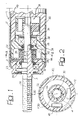
- Figure 1 is an axial sectional view of a transducer according to the invention;
- Figure 2 is a sectional view taken according to the line II-II of Figure 1;
- Figures 3 and 4 illustrate possible plots in time of the signals generated by a transducer according to the invention; and
- Figure 5 illustrates, in the form of a block diagram, a possible connection configuration of a transducer according to the invention and of the corresponding signal-processing circuits.
- In Figure 1 the reference number 1 designates, as a whole, a transducer of angular quantities for a cycle (for the meaning given to this term, the reader is referred to the terminological clarifications made at the beginning of the present description), which is basically made up of a fixed part, or stator, designated by 2, and a mobile part, or rotor, designated by 3.
- In the embodiment herein illustrated (which, it is recalled, is simply an example and refers in particular to the possible application of the transducer 1 on board a cycle), the fixed, or stator,
part 2 of the transducer 1 has an overall cylindrical/tubular shape and is made in such a way as to possess intrinsic characteristics of mechanical strength and resistance to impact, vibrations, as well as to external agents (temperature, water, oil and fuel, dust of various kinds, etc.) to which a component of this sort mounted on board a cycle is in general likely to be exposed. - The corresponding constructional particulars - which are to be deemed in themselves known - can be partly inferred from the drawings. It is pointed out that the said particulars are not in themselves essential for the purpose of understanding the implementation of the present invention.
- In brief, it may be noted that the
aforesaid stator part 2 usually comprises anouter shell 20, for example made of metal material, inserted in which are one or moreshaped bodies shell 20. - The overall annular or tubular structure of the
bodies shaft 30 which can rotate about its own axis X30. In the specific embodiment here illustrated, the axis X30 also identifies the main axis of theshell 20. - The transducer 1 is designed to supply at output signals indicating angular quantities (angular position, angular velocity, etc.) that are characteristic of the possible movement of the
shaft 30 with respect to theshell 20, and hence of the possible relative movement of parts and/or elements connected to theshaft 30 and to theshell 20. - The
shaft 30 may be either a "passive" shaft, i.e., designed to be driven by a member (not illustrated) the characteristics of rotation of which with respect to theshell 20 are to be detected, or an "active" shaft, which, by means of amechanism 31, actuates a mobile member (not specifically illustrated in the drawings), the above being the result of an action of driving in rotation of theshaft 30 exerted by a motor (not illustrated in the drawings but of a known type). - The transducer 1 illustrated in the drawings may possibly be integrated in a motor/actuator, such as the motor/actuator of a motor-driven gear change mounted on a cycle, such a competition bicycle.
- The
reference number 32 designates two bearings which support and guide theshaft 30 in a precise and regular movement of rotation of theshaft 30 with respect to the shell 20 (i.e., about the axis X30). - The
reference number 33 designates various seal elements, also of a known type, associated to thebearings 32 and/or to the end part of theshell 20. - Finally, the
reference number 34 designates two Belleville washers designed to apply, to the ensemble of parts just described, a slight axial elastic preload (i.e., in the direction of the axis X30) in order to prevent undesired vibrational phenomena and/or play. - Persons skilled in the art will, on the other hand, appreciate that the aforesaid constructional details have been illustrated herein purely by way of non-limiting example and clearly must not be interpreted as in any way limiting the scope of the present invention.
- An important characteristic of the solution according to the invention lies in the fact that mounted, for example in a
recess 35 made in the part of the stator designated by 22, is a set of Hall-effect sensors in turn comprising a fixed, or stator, part connected to thestator 2 and a mobile, or rotor, part connected to the rotor 3. - In particular, the fixed, or stator, part of the set of sensors comprises two Hall-
effect sensors 41, 42 (of a type in itself known) mounted angularly staggered with respect to one another by 90° (see the angle α in Figure 2) about the axis X30. - The
reference number 43 designates a set of supply/signal lines coming under thesensors base 44 having an annular shape. Thebase 44 surrounds theshaft 30, even though it is of course mounted in a fixed position with respect to thestator part 2 of the transducer 1. - The mobile, or rotor, part of the transducer instead consists of a ring of magnetized material (also in this case according to known criteria) fitted on the
shaft 30. Fitting may be, for example, with interposition of a tubular sleeve or bushing 37, which moves in rotation with theshaft 30 about the axis X30. - The overall result that may be obtained is the presence, on the signal cables - designated by 431 and 432 in the diagram of Figure 5 - of the
sensors - An important characteristic of the
sensors shaft 30 through 360 degrees) such as to be configured as linear or analog signals, i.e., signals the values of which vary over time within a range of possible values that vary in a continuous range, and not in a discrete range as in the case of digital signals. - Even though the currently preferred embodiment envisages the use of signals S1, S2 having a sinusoidal waveform, the solution according to the invention can be implemented also using signals of a different type, such as triangular signals, saw-tooth signals, etc.
- The solution according to the invention is suited for being implemented to particular advantage using linear, ratiometric (i.e., with the signal qualitatively unvarying as the voltage varies), temperature-compensated Hall-
effect sensors sensors - Sensors of the above type are able to generate output waveforms of the types represented in Figures 3 and 4, when a diametrically magnetized
ring 36 with a single pair of poles is used. - In view of the fact that the waveforms of the signals S1, S2 are practically invariant as the speed of rotation varies, the ensemble thus configured makes it possible to obtain, with a good degree of precision, the indication of the relative angular positions of the
shell 20 and of the shaft 30 (and hence of thestator part 2 and of the rotor part 3 of the transducer 1), at the same time without having to resort to sensor elements which, as in the case of potentiometric sensors, necessarily involve a contact, in particular a sliding contact, between the mobile part and the fixed part. - Both the output signals S1 and S2 are of an analog type. By means of an analog-to-digital conversion it is therefore possible to derive from the said signals numeric values corresponding to the signals measured. The degree of resolution depends uniquely upon the degree of resolution of the conversion and, consequently, can even be quite high without this resulting in a particularly complex transducer structure.
- The availability of the two signals S1 and S2 generated by the two
sensors - - i) the fact that the signal of each of the
sensors - - ii) the direction of rotation.
- Note in Figure 3 the two identical values assumed by the signal S1 for different values of rotation, such as, for instance, 45° and 135°. The ambiguity regarding the position may be solved if it is noted that, at the aforesaid values of angular position, whilst the signal S1 assumes the same value, the signal S2 assumes values of opposite sign. Consequently, given the same value assumed by S1, the position detected corresponds, for example, to 45° if the value of S2 is negative and to 135° if the value of S2 is positive.
- The above example, given for the sake simplicity with reference to the angular values of 45° and 135°, can obviously be applied to the four quadrants, i.e., to any angular position of rotation whatsoever of the
shaft 30 about the axis X30. - A comparison between Figure 3 and Figure 4 makes it possible to understand that the availability of the two signals S1 and S2 produced by the two
sensors - Suppose that when the
shaft 30 turns in one direction, the plots of the signals S1 and S2 are the ones represented in Figure 3. If the direction of rotation is reversed, the plots of the signals S1 and S2 become the ones represented in Figure 4. - In fact, with reference to the cross-sectional view of Figure 2:
- if the
shaft 30 turns in the counter-clockwise direction, the signal S1 of thesensor 41 "precedes" by 90° the signal S2 generated by the sensor 42 (see Figure 2); and - if the
shaft 30 turns in the clockwise direction, it is instead the signal S2 generated by thesensor 42 that "precedes" the signal S1 generated by the sensor 41 (see Figure 3). - The operation of discrimination of the direction of movement can therefore be carried out, for instance, by detecting the sign of the derivative of the signal S1 during the time intervals indicated by A in which the signal S2 assumes a positive value.
- Whilst in the case of Figure 3, the signal S1 has a negative derivative during the time intervals A, in the case of Figure 4 the said derivative is positive.
- The choice of either one of the signals S1 or S2 for performing said verification operations is in any case altogether indifferent. For example, it is possible to achieve the same result by detecting the sign of the derivative of the signal S2 during the time intervals in which the signal S1 has a positive value.
- Also performing the aforesaid verification of the direction of movement in the time intervals in which one of the signals has a positive value is purely and simply a matter of choice. The same result could in fact be achieved by carrying out the verification in the time intervals in which the signal considered has a negative value.
- Again, the same verification can be made without resorting to the detection of the sign of the derivatives of the signals. It may be readily appreciated (the corresponding verification operation may be carried out by means of any type of module that performs, also at a software level, the function of a flip-flop) that, in the direction of rotation to which Figure 3 refers, the half-periods in which the signal S1 is positive precede by 90° the half-periods in which the signal S2 is likewise positive. Instead, in the opposite direction of rotation, represented in Figure 4, it is the positive half-periods of the signal S2 that precede the positive half-periods of the signal S1 by 90°. Similar functions of detection can evidently be implemented using the negative half-periods of the signals S1 and S2.
- The diagrams of Figures 3 and 4 also show that the transducer 1 is able to perform its function also on a number of revolutions, a feature which may be important, for example, for controlling the position value reached by an actuator designed to perform its action on a number of revolutions. A typical example of the above application is that of electric motors for actuating motor-driven gear changes for bicycles.
- The types of components used for constructing the sensor according to the invention enables a position transducer to be provided that is able to overcome the difficulties that unavoidably beset alternative solutions of a potentiometric or optical type.
- The transducer according to the invention is of relatively simple construction and is robust from the standpoint of its application in a demanding environment characterized by the presence of dirt, vibrations, etc., as in cycling.
- The diagram of Figure 5 is a schematic illustration of the modalities of processing of the signals S1 and S2 generated by the transducer 1. The corresponding processing operations can be carried out in a
unit 50 integrated at a localized level (for example, using an integrated-microcontroller unit), or else located in a remote position, as in the case in which the aforesaid processing operations are performed in a centralized way by a control unit that also performs other processing functions inherent in the "cycle system". - Processing of the signals may involve processes of self-calibration, linearization, phase relation, etc. The foregoing processes are performed according to known criteria once the signals S1 and S2 present on the
signal lines converter 51 associated to theunit 50. - Once the signals S1 and S2 have been converted into digital form in the
unit 51, they can undergo processing within amodule 52 consisting, for example, of a microcontroller or a microprocessor (of a known type). - As an alternative to a direct use of the signals S1, S2 converted into digital form for processing purposes, the same signals can also be used for a search function in the framework of a conversion table (for example a look-up table) 53 associated to the
unit 52. - In this case, the signals S1, S2 are not used for further processing operations in the direct form (i.e., as they emerge from the analog-to-digital conversion operation), but are instead used to search for a pair of corresponding values in the table 53.
- The said pair of corresponding values is identified starting form the pair of values of the signals S1 and S2 emerging from the analog-to-digital conversion, according to a given criterion (for example, a criterion of minimum vector distance) or even according to fuzzy-type logic. This choice may be recommended, for example, for those applications in which the signal coming from the transducer 1 is to be used as a driving and/or parametric signal during execution of control operations and/or for implementation of algorithms in which the aim is to avoid undesired phenomena of error propagation.
- As already said - and without the above purely illustrative example being interpretable as in any way limiting the scope of the invention - a transducer according to the invention can be used, for example, in combination with the bottom bracket of a bicycle, with the mobile part driven by the latter. The information that can be obtained using the transducer may then be, for example:
- indication of movement of the chain;
- direction of said movement;
- pedal cadence; and/or
- angular position with respect to a reference point (for example, with respect to the so-called "preset shift points" or "fast-shift profiles" provided on the gear wheel driven by said bottom bracket to facilitate gear change).
- Of course, without prejudice to the principle of the invention, the details of construction and the embodiments may vary widely with respect to what is described and illustrated herein purely by way of example, without thereby departing from the scope of the present invention as defined in the annexed claims.
Claims (12)
- A transducer (1) of angular quantities for a cycle, comprising a first part (2) and a second part (3) which can perform a relative movement of rotation about a given axis (X30),
characterized in that it comprises:- a magnetized element (36) integrally fixed to one (3) of said first part (2) and said second part (3);- at least one pair of Hall-effect sensors (41, 42) set angularly staggered with respect to one another about said given axis (X30) and integrally fixed to the other (2) of said first part (2) and said second part (3);said Hall-effect sensors (41, 42) being sensitive to the presence of said magnetized element (36) so as to generate respective output signals (S1, S2) with values varying in a continuous range, the values of said respective output signals (S1, S2) uniquely identifying the relative position of said first part (2) and said second part (3) with respect to said given axis (X30). - The transducer according to Claim 1, characterized in that it comprises a pair of said Hall-effect sensors (41, 42) angularly staggered by 90° with respect to one another about said given axis (X30).
- The transducer according to Claim 1 or Claim 2, characterized in that said magnetized element (36) has an annular shape.
- The transducer according to any one of Claims 1 to 3, characterized in that said magnetized element (36) is magnetized at a single pair of poles in the diametral direction with respect to said given axis (X30).
- The transducer according to Claim 3 or Claim 4, characterized in that said magnetized element (36) is fitted around one (3) of said first part (2) and said second part (3).
- The transducer according to any one of the preceding claims, characterized in that it has associated thereto an analog-to-digital conversion unit (51) for converting said output signals (S1, S2) into corresponding digital signals.
- The transducer according to Claim 6, characterized in that said analog-to-digital conversion unit (51) is integrated in the transducer (1).
- The transducer according to Claim 6 or Claim 7, characterized in that it has associated thereto a processing unit (51) for processing said output signals (S1, S2) converted into digital form.
- The transducer according to Claim 8, characterized in that said processing unit (52) has associated thereto a conversion table (53) for generating, starting from said respective output signals (S1, S2) converted into digital form, further digital signals usable for processing purposes.
- The transducer according to Claim 8 or Claim 9, characterized in that said processing unit (52) is integrated in said transducer (1).
- The transducer according to any one of the preceding claims, associated to at least one component of a cycle, so that said respective output signals (S1, S2) indicate an angular quantity of said cycle component.
- Actuator for a motor-driven bicycle gear change characterized by comprising a transducer according to any one of the preceding claims.
Applications Claiming Priority (2)
| Application Number | Priority Date | Filing Date | Title |
|---|---|---|---|
| IT2001TO000730A ITTO20010730A1 (en) | 2001-07-24 | 2001-07-24 | ANGULAR SIZE TRANSDUCER. |
| ITTO20010730 | 2001-07-24 |
Publications (3)
| Publication Number | Publication Date |
|---|---|
| EP1279929A2 true EP1279929A2 (en) | 2003-01-29 |
| EP1279929A3 EP1279929A3 (en) | 2005-05-25 |
| EP1279929B1 EP1279929B1 (en) | 2011-02-09 |
Family
ID=11459084
Family Applications (1)
| Application Number | Title | Priority Date | Filing Date |
|---|---|---|---|
| EP02015834A Expired - Lifetime EP1279929B1 (en) | 2001-07-24 | 2002-07-16 | Transducer of angular quantities for a cycle |
Country Status (8)
| Country | Link |
|---|---|
| US (2) | US7009387B2 (en) |
| EP (1) | EP1279929B1 (en) |
| JP (1) | JP2003106807A (en) |
| CN (1) | CN1285888C (en) |
| AT (1) | ATE498112T1 (en) |
| DE (1) | DE60239116D1 (en) |
| IT (1) | ITTO20010730A1 (en) |
| TW (1) | TWI274879B (en) |
Cited By (11)
| Publication number | Priority date | Publication date | Assignee | Title |
|---|---|---|---|---|
| WO2007012419A3 (en) * | 2005-07-26 | 2007-04-12 | Ebm Papst St Georgen Gmbh & Co | Absolute encoder and method for generating an absolute value for an angle of rotation |
| EP2030890A1 (en) * | 2007-08-21 | 2009-03-04 | Shimano Inc. | Bicycle component with position sensing |
| WO2014019406A1 (en) * | 2012-07-28 | 2014-02-06 | 高松 | Sensor having multiple magnet blocks of unevenly distributed positions and magnetic fluxes in housing |
| WO2014019407A1 (en) * | 2012-07-28 | 2014-02-06 | 高松 | Sensor having multiple magnetic blocks of adjustable positions in housing |
| ITMI20131064A1 (en) * | 2013-06-26 | 2014-12-27 | Campagnolo Srl | ELECTRONIC BICYCLE SYSTEM |
| EP3028936A1 (en) | 2014-12-02 | 2016-06-08 | Campagnolo S.R.L. | Derailleur of a bicycle gearshift |
| EP3028935A1 (en) | 2014-12-02 | 2016-06-08 | Campagnolo S.R.L. | Method for electronically controlling a bicycle gearshift and bicycle electric gearshift |
| CN108871639A (en) * | 2018-05-07 | 2018-11-23 | 重庆三叶花科技有限公司 | Axis moment inspecting system |
| WO2023213554A1 (en) * | 2022-05-04 | 2023-11-09 | Robert Bosch Gmbh | Device for detecting a rearward movement of an electric bicycle |
| IT202200009935A1 (en) * | 2022-05-13 | 2023-11-13 | Campagnolo Srl | Electric/electronic bicycle derailleur with articulated parallelogram |
| WO2026057977A1 (en) * | 2024-09-10 | 2026-03-19 | Ebike Systems Ltd | Electrically-assisted pedal cycles |
Families Citing this family (30)
| Publication number | Priority date | Publication date | Assignee | Title |
|---|---|---|---|---|
| US7317313B2 (en) * | 2002-11-14 | 2008-01-08 | Measurement Specialties, Inc. | Magnetic encoder apparatus |
| FR2871880B1 (en) * | 2004-06-18 | 2006-08-11 | Siemens Vdo Automotive Sas | DEVICE AND METHOD FOR DETERMINING THE POSITION OF AN ENGINE |
| US20070008063A1 (en) * | 2004-08-13 | 2007-01-11 | Cts Corporation | Rotary actuator with non-contacting position sensor |
| JP4574406B2 (en) * | 2005-03-18 | 2010-11-04 | 株式会社小松製作所 | Stroke position measuring device of hydraulic cylinder in hydraulic work machine |
| US7552897B2 (en) * | 2005-07-14 | 2009-06-30 | The Boeing Company | Method and system for rotary code-based control |
| US20070251474A1 (en) * | 2006-05-01 | 2007-11-01 | Gauthier Daniel G | Cam phasing system with mid-range engine shutdown |
| US20080084202A1 (en) * | 2006-10-06 | 2008-04-10 | Acewell International Co., Ltd. | Vehicular rotation speed sensing apparatus |
| US8137223B2 (en) | 2007-05-16 | 2012-03-20 | Shimano Inc. | Bicycle rear derailleur |
| CN102326053B (en) | 2009-02-17 | 2015-02-18 | Cts公司 | Rotary position sensor |
| US8117923B2 (en) * | 2009-05-08 | 2012-02-21 | Shimano Inc. | Bicycle bottom bracket force sensor |
| CN101701791B (en) * | 2009-10-27 | 2011-01-19 | 华中科技大学 | Angular displacement sensor |
| DE102009046387A1 (en) * | 2009-11-04 | 2011-05-05 | Robert Bosch Gmbh | Pedal travel transmitter and pedal unit |
| US8378673B2 (en) * | 2010-11-09 | 2013-02-19 | Techway Industrial Co., Ltd. | Derailleur cable detecting assembly for an electric-auxiliary bicycle |
| US9651138B2 (en) | 2011-09-30 | 2017-05-16 | Mtd Products Inc. | Speed control assembly for a self-propelled walk-behind lawn mower |
| US9394030B2 (en) * | 2012-09-27 | 2016-07-19 | Sram, Llc | Rear derailleur |
| US9676444B2 (en) | 2013-10-23 | 2017-06-13 | Sram, Llc | Electromechanical rear derailleur |
| US9953594B2 (en) * | 2013-11-15 | 2018-04-24 | Sharp Kabushiki Kaisha | Liquid crystal display device and method for driving same |
| JP6318784B2 (en) * | 2014-04-04 | 2018-05-09 | ソニー株式会社 | Rotational speed detection device, rotational speed detection method, and program |
| CN105270559A (en) * | 2014-10-22 | 2016-01-27 | 天津比沃科技有限公司 | Detection mechanism of speed change mechanism of electric bicycle, and speed changing method of electric bicycle |
| TWI564182B (en) | 2015-03-26 | 2017-01-01 | 鴻海精密工業股份有限公司 | Electric bicycle and torque sensor thereof |
| TWI565603B (en) | 2015-03-26 | 2017-01-11 | 鴻海精密工業股份有限公司 | Electric bicycle and torque sensor thereof |
| JP6499028B2 (en) * | 2015-06-25 | 2019-04-10 | 株式会社シマノ | Bicycle shift control device for controlling transmission and bicycle shift control system including transmission |
| US9944350B2 (en) | 2016-01-11 | 2018-04-17 | Sram, Llc | Chain guide sensor and methods of controling a bicycle |
| JP7149325B2 (en) * | 2017-05-05 | 2022-10-06 | 捷安特電動車(昆山)有限公司 | Device for detecting operating parameters of a vehicle |
| CN108791681A (en) * | 2017-05-05 | 2018-11-13 | 捷安特电动车(昆山)有限公司 | A kind of device measuring axis double-side torque, position angle, rotating speed and power |
| CN108801297A (en) * | 2017-05-05 | 2018-11-13 | 捷安特电动车(昆山)有限公司 | A kind of device detecting axis double-side torque, position angle, rotating speed and power |
| DE102018219581B4 (en) * | 2018-11-15 | 2022-10-06 | Infineon Technologies Ag | METHOD AND DEVICE FOR DETECTING A RELATIVE DIRECTION OF MOVEMENT AND WHEEL SPEED SENSOR |
| KR102120197B1 (en) * | 2018-12-20 | 2020-06-08 | 에스앤티모티브 주식회사 | Actuator Assembly of Transfer case |
| WO2021019980A1 (en) * | 2019-07-31 | 2021-02-04 | 日信工業株式会社 | Operation amount detection device for bar handle vehicle |
| US20240111004A1 (en) * | 2022-10-03 | 2024-04-04 | Panda Hardware LLC | Hall effect sensor assembly for use with game controller joysticks |
Family Cites Families (19)
| Publication number | Priority date | Publication date | Assignee | Title |
|---|---|---|---|---|
| US4570118A (en) | 1981-11-20 | 1986-02-11 | Gulf & Western Manufacturing Company | Angular position transducer including permanent magnets and Hall Effect device |
| FR2660028B1 (en) * | 1990-03-20 | 1994-12-09 | Roulements Soc Nouvelle | BEARING WITH ANGULAR POSITION SENSOR. |
| DE69231799T2 (en) * | 1991-06-04 | 2001-08-09 | Yamaha Hatsudoki K.K., Iwata | Muscle-powered vehicle |
| US5257014A (en) * | 1991-10-31 | 1993-10-26 | Caterpillar Inc. | Actuator detection method and apparatus for an electromechanical actuator |
| US5332965A (en) | 1992-06-22 | 1994-07-26 | Durakool Incorporated | Contactless linear angular position sensor having an adjustable flux concentrator for sensitivity adjustment and temperature compensation |
| US5497081A (en) | 1992-06-22 | 1996-03-05 | Durakool Incorporated | Mechanically adjustable linear-output angular position sensor |
| US5475305A (en) * | 1993-02-18 | 1995-12-12 | Iowa State University Research Foundation, Inc. | Magnetic inspection probe for measurement of magnetic anisotropy |
| DE9302758U1 (en) * | 1993-02-25 | 1994-03-31 | Siemens AG, 80333 München | Magnetic angular position and speed encoder |
| IT1266817B1 (en) * | 1994-02-24 | 1997-01-21 | Campagnolo Srl | SPEED CHANGE DEVICE FOR BICYCLES. |
| US5880586A (en) * | 1994-11-22 | 1999-03-09 | Robert Bosch Gmbh | Apparatus for determining rotational position of a rotatable element without contacting it |
| DE19630764A1 (en) * | 1995-09-29 | 1997-04-03 | Bosch Gmbh Robert | Contact free identification device for relative movement |
| DE19640695A1 (en) | 1996-10-02 | 1998-04-09 | Bosch Gmbh Robert | Magnetoresistive sensor with temperature-stable zero point |
| DE19716985A1 (en) * | 1997-04-23 | 1998-10-29 | A B Elektronik Gmbh | Device for determining the position and / or torsion of rotating shafts |
| DE19817356A1 (en) * | 1998-04-18 | 1999-10-21 | Bosch Gmbh Robert | Angle indicator for determining an angle between a sensor arrangement and a magnetic field |
| US6196347B1 (en) * | 1998-09-22 | 2001-03-06 | Industrial Technology Research Institute | Power transmission and pedal force sensing system for an electric bicycle |
| CN1078765C (en) * | 1999-05-04 | 2002-01-30 | 李宜和 | Auxiliary power motor with improved structure |
| DE19953190C2 (en) * | 1999-11-05 | 2002-11-07 | Bosch Gmbh Robert | Sensor arrangement for detecting an angle of rotation |
| JP3638483B2 (en) * | 1999-11-10 | 2005-04-13 | 株式会社マキタ | Charging device and charging method |
| US6429647B1 (en) * | 2000-03-17 | 2002-08-06 | Delphi Technologies, Inc. | Angular position sensor and method of making |
-
2001
- 2001-07-24 IT IT2001TO000730A patent/ITTO20010730A1/en unknown
- 2001-10-03 TW TW094100304A patent/TWI274879B/en not_active IP Right Cessation
-
2002
- 2002-07-16 AT AT02015834T patent/ATE498112T1/en not_active IP Right Cessation
- 2002-07-16 DE DE60239116T patent/DE60239116D1/en not_active Expired - Lifetime
- 2002-07-16 EP EP02015834A patent/EP1279929B1/en not_active Expired - Lifetime
- 2002-07-24 CN CN02126570.4A patent/CN1285888C/en not_active Expired - Fee Related
- 2002-07-24 US US10/205,181 patent/US7009387B2/en not_active Expired - Lifetime
- 2002-07-24 JP JP2002215236A patent/JP2003106807A/en active Pending
-
2006
- 2006-03-07 US US11/369,273 patent/US7276899B2/en not_active Expired - Fee Related
Cited By (20)
| Publication number | Priority date | Publication date | Assignee | Title |
|---|---|---|---|---|
| US8324892B2 (en) | 2005-07-26 | 2012-12-04 | Ebm-Papst St. Georgen Gmbh & Co. Kg | Absolute encoder and method for generating an absolute value for a angle of rotation |
| WO2007012419A3 (en) * | 2005-07-26 | 2007-04-12 | Ebm Papst St Georgen Gmbh & Co | Absolute encoder and method for generating an absolute value for an angle of rotation |
| EP2030890A1 (en) * | 2007-08-21 | 2009-03-04 | Shimano Inc. | Bicycle component with position sensing |
| WO2014019406A1 (en) * | 2012-07-28 | 2014-02-06 | 高松 | Sensor having multiple magnet blocks of unevenly distributed positions and magnetic fluxes in housing |
| WO2014019407A1 (en) * | 2012-07-28 | 2014-02-06 | 高松 | Sensor having multiple magnetic blocks of adjustable positions in housing |
| US9469376B2 (en) | 2013-06-26 | 2016-10-18 | Campagnolo S.R.L. | Electronic bicycle system |
| ITMI20131064A1 (en) * | 2013-06-26 | 2014-12-27 | Campagnolo Srl | ELECTRONIC BICYCLE SYSTEM |
| EP2818394A1 (en) | 2013-06-26 | 2014-12-31 | Campagnolo S.R.L. | Electronic bicycle system |
| US9650108B2 (en) | 2014-12-02 | 2017-05-16 | Campagnolo S.R.L. | Derailleur of a bicycle gearshift and method for electronically controlling a bicycle gearshift |
| EP3028935A1 (en) | 2014-12-02 | 2016-06-08 | Campagnolo S.R.L. | Method for electronically controlling a bicycle gearshift and bicycle electric gearshift |
| EP3028936A1 (en) | 2014-12-02 | 2016-06-08 | Campagnolo S.R.L. | Derailleur of a bicycle gearshift |
| US9758217B2 (en) | 2014-12-02 | 2017-09-12 | Campagnolo S.R.L. | Derailleur of a bicycle gearshift and method for electronically controlling a bicycle gearshift |
| US10668983B2 (en) | 2014-12-02 | 2020-06-02 | Campagnolo S.R.L. | Derailleur of a bicycle gearshift and method for electronically controlling a bicycle gearshift |
| CN108871639A (en) * | 2018-05-07 | 2018-11-23 | 重庆三叶花科技有限公司 | Axis moment inspecting system |
| CN108871639B (en) * | 2018-05-07 | 2020-10-16 | 重庆三叶花科技有限公司 | Center shaft moment detection system |
| WO2023213554A1 (en) * | 2022-05-04 | 2023-11-09 | Robert Bosch Gmbh | Device for detecting a rearward movement of an electric bicycle |
| IT202200009935A1 (en) * | 2022-05-13 | 2023-11-13 | Campagnolo Srl | Electric/electronic bicycle derailleur with articulated parallelogram |
| EP4276003A1 (en) * | 2022-05-13 | 2023-11-15 | Campagnolo S.r.l. | Bicycle electric/electronic derailleur of the articulated parallelogram type |
| US12024263B2 (en) | 2022-05-13 | 2024-07-02 | Campagnolo S.R.L. | Articulated parallelogram bicycle electric/electronic derailleur |
| WO2026057977A1 (en) * | 2024-09-10 | 2026-03-19 | Ebike Systems Ltd | Electrically-assisted pedal cycles |
Also Published As
| Publication number | Publication date |
|---|---|
| ITTO20010730A1 (en) | 2003-01-24 |
| JP2003106807A (en) | 2003-04-09 |
| TW200523548A (en) | 2005-07-16 |
| ATE498112T1 (en) | 2011-02-15 |
| US7276899B2 (en) | 2007-10-02 |
| US20060145688A1 (en) | 2006-07-06 |
| ITTO20010730A0 (en) | 2001-07-24 |
| US20030038625A1 (en) | 2003-02-27 |
| DE60239116D1 (en) | 2011-03-24 |
| US7009387B2 (en) | 2006-03-07 |
| EP1279929B1 (en) | 2011-02-09 |
| EP1279929A3 (en) | 2005-05-25 |
| CN1399121A (en) | 2003-02-26 |
| CN1285888C (en) | 2006-11-22 |
| TWI274879B (en) | 2007-03-01 |
Similar Documents
| Publication | Publication Date | Title |
|---|---|---|
| EP1279929B1 (en) | Transducer of angular quantities for a cycle | |
| JP5480967B2 (en) | Multi-period absolute position detector | |
| KR101497740B1 (en) | Non-contact multi-turn absolute position magnetic sensor comprising a through-shaft | |
| JP6877170B2 (en) | Rotary encoder and its absolute angle position detection method | |
| AU775247B2 (en) | Device for measuring the angle and/or the angular velocity of a rotatable body and/or the torque acting upon said body | |
| JP2002522760A (en) | Sensor device for detecting rotation angle and / or torque | |
| US7366636B2 (en) | Rotational angle detector | |
| JP5435450B2 (en) | Rotation angle detection device and rotation angle detection method | |
| US7213341B2 (en) | Device for determining an absolute angle of rotation | |
| WO2004081490A1 (en) | Rotation angle-detecting device | |
| EP1988367B1 (en) | Bearing assembly with built-in absolute encoder | |
| US20100097051A1 (en) | Incremental position, speed and direction detection apparatus and method for rotating targets utilizing magnetoresistive sensor | |
| KR20150097678A (en) | Method for detecting a torque applied to a shaft | |
| CN113054804A (en) | Magnetic encoder and motor rotation position measuring device | |
| US20060174499A1 (en) | Device for determining an absolute angle of rotation | |
| WO2006013622A1 (en) | Bearing with absolute angle sensor | |
| CN110873585A (en) | Grating encoder and device thereof | |
| JP2024502666A (en) | Non-contact position sensor with permanent magnet, measuring device, application method of non-contact position sensor | |
| JP7709324B2 (en) | Torque measuring device, magnetic field generating device for a torque measuring device, and magnetic field detecting device for a torque measuring device | |
| TWM287436U (en) | Transducer of angular quantities | |
| JP2026068858A (en) | Magnetic encoder device | |
| CN205352423U (en) | Reluctance type one -loop absolute type photoelectric encoder |
Legal Events
| Date | Code | Title | Description |
|---|---|---|---|
| PUAI | Public reference made under article 153(3) epc to a published international application that has entered the european phase |
Free format text: ORIGINAL CODE: 0009012 |
|
| AK | Designated contracting states |
Designated state(s): AT BE BG CH CY CZ DE DK EE ES FI FR GB GR IE IT LI LU MC NL PT SE SK TR |
|
| AX | Request for extension of the european patent |
Extension state: AL LT LV MK RO SI |
|
| PUAL | Search report despatched |
Free format text: ORIGINAL CODE: 0009013 |
|
| AK | Designated contracting states |
Kind code of ref document: A3 Designated state(s): AT BE BG CH CY CZ DE DK EE ES FI FR GB GR IE IT LI LU MC NL PT SE SK TR |
|
| AX | Request for extension of the european patent |
Extension state: AL LT LV MK RO SI |
|
| 17P | Request for examination filed |
Effective date: 20051116 |
|
| AKX | Designation fees paid |
Designated state(s): AT BE BG CH CY CZ DE DK EE ES FI FR GB GR IE IT LI LU MC NL PT SE SK TR |
|
| 17Q | First examination report despatched |
Effective date: 20091130 |
|
| GRAP | Despatch of communication of intention to grant a patent |
Free format text: ORIGINAL CODE: EPIDOSNIGR1 |
|
| GRAS | Grant fee paid |
Free format text: ORIGINAL CODE: EPIDOSNIGR3 |
|
| GRAA | (expected) grant |
Free format text: ORIGINAL CODE: 0009210 |
|
| AK | Designated contracting states |
Kind code of ref document: B1 Designated state(s): AT BE BG CH CY CZ DE DK EE ES FI FR GB GR IE IT LI LU MC NL PT SE SK TR |
|
| REG | Reference to a national code |
Ref country code: GB Ref legal event code: FG4D |
|
| REG | Reference to a national code |
Ref country code: CH Ref legal event code: EP |
|
| REG | Reference to a national code |
Ref country code: IE Ref legal event code: FG4D |
|
| REF | Corresponds to: |
Ref document number: 60239116 Country of ref document: DE Date of ref document: 20110324 Kind code of ref document: P |
|
| REG | Reference to a national code |
Ref country code: DE Ref legal event code: R096 Ref document number: 60239116 Country of ref document: DE Effective date: 20110324 |
|
| REG | Reference to a national code |
Ref country code: NL Ref legal event code: VDEP Effective date: 20110209 |
|
| PG25 | Lapsed in a contracting state [announced via postgrant information from national office to epo] |
Ref country code: GR Free format text: LAPSE BECAUSE OF FAILURE TO SUBMIT A TRANSLATION OF THE DESCRIPTION OR TO PAY THE FEE WITHIN THE PRESCRIBED TIME-LIMIT Effective date: 20110510 Ref country code: SE Free format text: LAPSE BECAUSE OF FAILURE TO SUBMIT A TRANSLATION OF THE DESCRIPTION OR TO PAY THE FEE WITHIN THE PRESCRIBED TIME-LIMIT Effective date: 20110209 Ref country code: PT Free format text: LAPSE BECAUSE OF FAILURE TO SUBMIT A TRANSLATION OF THE DESCRIPTION OR TO PAY THE FEE WITHIN THE PRESCRIBED TIME-LIMIT Effective date: 20110609 Ref country code: ES Free format text: LAPSE BECAUSE OF FAILURE TO SUBMIT A TRANSLATION OF THE DESCRIPTION OR TO PAY THE FEE WITHIN THE PRESCRIBED TIME-LIMIT Effective date: 20110520 |
|
| PG25 | Lapsed in a contracting state [announced via postgrant information from national office to epo] |
Ref country code: NL Free format text: LAPSE BECAUSE OF FAILURE TO SUBMIT A TRANSLATION OF THE DESCRIPTION OR TO PAY THE FEE WITHIN THE PRESCRIBED TIME-LIMIT Effective date: 20110209 Ref country code: BE Free format text: LAPSE BECAUSE OF FAILURE TO SUBMIT A TRANSLATION OF THE DESCRIPTION OR TO PAY THE FEE WITHIN THE PRESCRIBED TIME-LIMIT Effective date: 20110209 Ref country code: FI Free format text: LAPSE BECAUSE OF FAILURE TO SUBMIT A TRANSLATION OF THE DESCRIPTION OR TO PAY THE FEE WITHIN THE PRESCRIBED TIME-LIMIT Effective date: 20110209 Ref country code: CY Free format text: LAPSE BECAUSE OF FAILURE TO SUBMIT A TRANSLATION OF THE DESCRIPTION OR TO PAY THE FEE WITHIN THE PRESCRIBED TIME-LIMIT Effective date: 20110209 Ref country code: BG Free format text: LAPSE BECAUSE OF FAILURE TO SUBMIT A TRANSLATION OF THE DESCRIPTION OR TO PAY THE FEE WITHIN THE PRESCRIBED TIME-LIMIT Effective date: 20110509 Ref country code: AT Free format text: LAPSE BECAUSE OF FAILURE TO SUBMIT A TRANSLATION OF THE DESCRIPTION OR TO PAY THE FEE WITHIN THE PRESCRIBED TIME-LIMIT Effective date: 20110209 |
|
| PG25 | Lapsed in a contracting state [announced via postgrant information from national office to epo] |
Ref country code: EE Free format text: LAPSE BECAUSE OF FAILURE TO SUBMIT A TRANSLATION OF THE DESCRIPTION OR TO PAY THE FEE WITHIN THE PRESCRIBED TIME-LIMIT Effective date: 20110209 Ref country code: DK Free format text: LAPSE BECAUSE OF FAILURE TO SUBMIT A TRANSLATION OF THE DESCRIPTION OR TO PAY THE FEE WITHIN THE PRESCRIBED TIME-LIMIT Effective date: 20110209 |
|
| PG25 | Lapsed in a contracting state [announced via postgrant information from national office to epo] |
Ref country code: SK Free format text: LAPSE BECAUSE OF FAILURE TO SUBMIT A TRANSLATION OF THE DESCRIPTION OR TO PAY THE FEE WITHIN THE PRESCRIBED TIME-LIMIT Effective date: 20110209 Ref country code: CZ Free format text: LAPSE BECAUSE OF FAILURE TO SUBMIT A TRANSLATION OF THE DESCRIPTION OR TO PAY THE FEE WITHIN THE PRESCRIBED TIME-LIMIT Effective date: 20110209 |
|
| PLBE | No opposition filed within time limit |
Free format text: ORIGINAL CODE: 0009261 |
|
| STAA | Information on the status of an ep patent application or granted ep patent |
Free format text: STATUS: NO OPPOSITION FILED WITHIN TIME LIMIT |
|
| 26N | No opposition filed |
Effective date: 20111110 |
|
| PG25 | Lapsed in a contracting state [announced via postgrant information from national office to epo] |
Ref country code: MC Free format text: LAPSE BECAUSE OF NON-PAYMENT OF DUE FEES Effective date: 20110731 |
|
| REG | Reference to a national code |
Ref country code: CH Ref legal event code: PL |
|
| REG | Reference to a national code |
Ref country code: DE Ref legal event code: R097 Ref document number: 60239116 Country of ref document: DE Effective date: 20111110 |
|
| GBPC | Gb: european patent ceased through non-payment of renewal fee |
Effective date: 20110716 |
|
| REG | Reference to a national code |
Ref country code: IE Ref legal event code: MM4A |
|
| PG25 | Lapsed in a contracting state [announced via postgrant information from national office to epo] |
Ref country code: LI Free format text: LAPSE BECAUSE OF NON-PAYMENT OF DUE FEES Effective date: 20110731 Ref country code: CH Free format text: LAPSE BECAUSE OF NON-PAYMENT OF DUE FEES Effective date: 20110731 |
|
| PG25 | Lapsed in a contracting state [announced via postgrant information from national office to epo] |
Ref country code: GB Free format text: LAPSE BECAUSE OF NON-PAYMENT OF DUE FEES Effective date: 20110716 |
|
| PG25 | Lapsed in a contracting state [announced via postgrant information from national office to epo] |
Ref country code: IE Free format text: LAPSE BECAUSE OF NON-PAYMENT OF DUE FEES Effective date: 20110716 |
|
| PG25 | Lapsed in a contracting state [announced via postgrant information from national office to epo] |
Ref country code: LU Free format text: LAPSE BECAUSE OF NON-PAYMENT OF DUE FEES Effective date: 20110716 |
|
| PG25 | Lapsed in a contracting state [announced via postgrant information from national office to epo] |
Ref country code: TR Free format text: LAPSE BECAUSE OF FAILURE TO SUBMIT A TRANSLATION OF THE DESCRIPTION OR TO PAY THE FEE WITHIN THE PRESCRIBED TIME-LIMIT Effective date: 20110209 |
|
| REG | Reference to a national code |
Ref country code: FR Ref legal event code: PLFP Year of fee payment: 15 |
|
| REG | Reference to a national code |
Ref country code: FR Ref legal event code: PLFP Year of fee payment: 16 |
|
| PGFP | Annual fee paid to national office [announced via postgrant information from national office to epo] |
Ref country code: DE Payment date: 20170727 Year of fee payment: 16 Ref country code: IT Payment date: 20170725 Year of fee payment: 16 Ref country code: FR Payment date: 20170726 Year of fee payment: 16 |
|
| REG | Reference to a national code |
Ref country code: DE Ref legal event code: R119 Ref document number: 60239116 Country of ref document: DE |
|
| PG25 | Lapsed in a contracting state [announced via postgrant information from national office to epo] |
Ref country code: FR Free format text: LAPSE BECAUSE OF NON-PAYMENT OF DUE FEES Effective date: 20180731 Ref country code: DE Free format text: LAPSE BECAUSE OF NON-PAYMENT OF DUE FEES Effective date: 20190201 |
|
| PG25 | Lapsed in a contracting state [announced via postgrant information from national office to epo] |
Ref country code: IT Free format text: LAPSE BECAUSE OF NON-PAYMENT OF DUE FEES Effective date: 20180716 |