EP1279912B1 - Methods of collecting and thawing polarised gases, associated accumulators and heating jackets - Google Patents
Methods of collecting and thawing polarised gases, associated accumulators and heating jackets Download PDFInfo
- Publication number
- EP1279912B1 EP1279912B1 EP02022943A EP02022943A EP1279912B1 EP 1279912 B1 EP1279912 B1 EP 1279912B1 EP 02022943 A EP02022943 A EP 02022943A EP 02022943 A EP02022943 A EP 02022943A EP 1279912 B1 EP1279912 B1 EP 1279912B1
- Authority
- EP
- European Patent Office
- Prior art keywords
- gas
- accumulator
- flow channel
- polarized
- channel
- Prior art date
- Legal status (The legal status is an assumption and is not a legal conclusion. Google has not performed a legal analysis and makes no representation as to the accuracy of the status listed.)
- Expired - Lifetime
Links
Images








Classifications
-
- G—PHYSICS
- G01—MEASURING; TESTING
- G01R—MEASURING ELECTRIC VARIABLES; MEASURING MAGNETIC VARIABLES
- G01R33/00—Arrangements or instruments for measuring magnetic variables
- G01R33/20—Arrangements or instruments for measuring magnetic variables involving magnetic resonance
- G01R33/28—Details of apparatus provided for in groups G01R33/44 - G01R33/64
-
- A—HUMAN NECESSITIES
- A61—MEDICAL OR VETERINARY SCIENCE; HYGIENE
- A61K—PREPARATIONS FOR MEDICAL, DENTAL OR TOILETRY PURPOSES
- A61K49/00—Preparations for testing in vivo
- A61K49/06—Nuclear magnetic resonance [NMR] contrast preparations; Magnetic resonance imaging [MRI] contrast preparations
- A61K49/18—Nuclear magnetic resonance [NMR] contrast preparations; Magnetic resonance imaging [MRI] contrast preparations characterised by a special physical form, e.g. emulsions, microcapsules, liposomes
- A61K49/1806—Suspensions, emulsions, colloids, dispersions
- A61K49/1815—Suspensions, emulsions, colloids, dispersions compo-inhalant, e.g. breath tests
-
- B—PERFORMING OPERATIONS; TRANSPORTING
- B01—PHYSICAL OR CHEMICAL PROCESSES OR APPARATUS IN GENERAL
- B01J—CHEMICAL OR PHYSICAL PROCESSES, e.g. CATALYSIS OR COLLOID CHEMISTRY; THEIR RELEVANT APPARATUS
- B01J19/00—Chemical, physical or physico-chemical processes in general; Their relevant apparatus
- B01J19/26—Nozzle-type reactors, i.e. the distribution of the initial reactants within the reactor is effected by their introduction or injection through nozzles
-
- F—MECHANICAL ENGINEERING; LIGHTING; HEATING; WEAPONS; BLASTING
- F25—REFRIGERATION OR COOLING; COMBINED HEATING AND REFRIGERATION SYSTEMS; HEAT PUMP SYSTEMS; MANUFACTURE OR STORAGE OF ICE; LIQUEFACTION SOLIDIFICATION OF GASES
- F25J—LIQUEFACTION, SOLIDIFICATION OR SEPARATION OF GASES OR GASEOUS OR LIQUEFIED GASEOUS MIXTURES BY PRESSURE AND COLD TREATMENT OR BY BRINGING THEM INTO THE SUPERCRITICAL STATE
- F25J3/00—Processes or apparatus for separating the constituents of gaseous or liquefied gaseous mixtures involving the use of liquefaction or solidification
- F25J3/06—Processes or apparatus for separating the constituents of gaseous or liquefied gaseous mixtures involving the use of liquefaction or solidification by partial condensation
- F25J3/063—Processes or apparatus for separating the constituents of gaseous or liquefied gaseous mixtures involving the use of liquefaction or solidification by partial condensation characterised by the separated product stream
- F25J3/0685—Processes or apparatus for separating the constituents of gaseous or liquefied gaseous mixtures involving the use of liquefaction or solidification by partial condensation characterised by the separated product stream separation of noble gases
-
- B—PERFORMING OPERATIONS; TRANSPORTING
- B01—PHYSICAL OR CHEMICAL PROCESSES OR APPARATUS IN GENERAL
- B01J—CHEMICAL OR PHYSICAL PROCESSES, e.g. CATALYSIS OR COLLOID CHEMISTRY; THEIR RELEVANT APPARATUS
- B01J2219/00—Chemical, physical or physico-chemical processes in general; Their relevant apparatus
- B01J2219/00049—Controlling or regulating processes
- B01J2219/00051—Controlling the temperature
- B01J2219/00074—Controlling the temperature by indirect heating or cooling employing heat exchange fluids
- B01J2219/00087—Controlling the temperature by indirect heating or cooling employing heat exchange fluids with heat exchange elements outside the reactor
- B01J2219/00099—Controlling the temperature by indirect heating or cooling employing heat exchange fluids with heat exchange elements outside the reactor the reactor being immersed in the heat exchange medium
-
- B—PERFORMING OPERATIONS; TRANSPORTING
- B01—PHYSICAL OR CHEMICAL PROCESSES OR APPARATUS IN GENERAL
- B01J—CHEMICAL OR PHYSICAL PROCESSES, e.g. CATALYSIS OR COLLOID CHEMISTRY; THEIR RELEVANT APPARATUS
- B01J2219/00—Chemical, physical or physico-chemical processes in general; Their relevant apparatus
- B01J2219/00049—Controlling or regulating processes
- B01J2219/00051—Controlling the temperature
- B01J2219/00074—Controlling the temperature by indirect heating or cooling employing heat exchange fluids
- B01J2219/00119—Heat exchange inside a feeding nozzle or nozzle reactor
-
- F—MECHANICAL ENGINEERING; LIGHTING; HEATING; WEAPONS; BLASTING
- F25—REFRIGERATION OR COOLING; COMBINED HEATING AND REFRIGERATION SYSTEMS; HEAT PUMP SYSTEMS; MANUFACTURE OR STORAGE OF ICE; LIQUEFACTION SOLIDIFICATION OF GASES
- F25J—LIQUEFACTION, SOLIDIFICATION OR SEPARATION OF GASES OR GASEOUS OR LIQUEFIED GASEOUS MIXTURES BY PRESSURE AND COLD TREATMENT OR BY BRINGING THEM INTO THE SUPERCRITICAL STATE
- F25J2205/00—Processes or apparatus using other separation and/or other processing means
- F25J2205/20—Processes or apparatus using other separation and/or other processing means using solidification of components
-
- F—MECHANICAL ENGINEERING; LIGHTING; HEATING; WEAPONS; BLASTING
- F25—REFRIGERATION OR COOLING; COMBINED HEATING AND REFRIGERATION SYSTEMS; HEAT PUMP SYSTEMS; MANUFACTURE OR STORAGE OF ICE; LIQUEFACTION SOLIDIFICATION OF GASES
- F25J—LIQUEFACTION, SOLIDIFICATION OR SEPARATION OF GASES OR GASEOUS OR LIQUEFIED GASEOUS MIXTURES BY PRESSURE AND COLD TREATMENT OR BY BRINGING THEM INTO THE SUPERCRITICAL STATE
- F25J2210/00—Processes characterised by the type or other details of the feed stream
- F25J2210/42—Nitrogen
-
- F—MECHANICAL ENGINEERING; LIGHTING; HEATING; WEAPONS; BLASTING
- F25—REFRIGERATION OR COOLING; COMBINED HEATING AND REFRIGERATION SYSTEMS; HEAT PUMP SYSTEMS; MANUFACTURE OR STORAGE OF ICE; LIQUEFACTION SOLIDIFICATION OF GASES
- F25J—LIQUEFACTION, SOLIDIFICATION OR SEPARATION OF GASES OR GASEOUS OR LIQUEFIED GASEOUS MIXTURES BY PRESSURE AND COLD TREATMENT OR BY BRINGING THEM INTO THE SUPERCRITICAL STATE
- F25J2215/00—Processes characterised by the type or other details of the product stream
- F25J2215/36—Xenon
-
- F—MECHANICAL ENGINEERING; LIGHTING; HEATING; WEAPONS; BLASTING
- F25—REFRIGERATION OR COOLING; COMBINED HEATING AND REFRIGERATION SYSTEMS; HEAT PUMP SYSTEMS; MANUFACTURE OR STORAGE OF ICE; LIQUEFACTION SOLIDIFICATION OF GASES
- F25J—LIQUEFACTION, SOLIDIFICATION OR SEPARATION OF GASES OR GASEOUS OR LIQUEFIED GASEOUS MIXTURES BY PRESSURE AND COLD TREATMENT OR BY BRINGING THEM INTO THE SUPERCRITICAL STATE
- F25J2240/00—Processes or apparatus involving steps for expanding of process streams
- F25J2240/40—Expansion without extracting work, i.e. isenthalpic throttling, e.g. JT valve, regulating valve or venturi, or isentropic nozzle, e.g. Laval
-
- F—MECHANICAL ENGINEERING; LIGHTING; HEATING; WEAPONS; BLASTING
- F25—REFRIGERATION OR COOLING; COMBINED HEATING AND REFRIGERATION SYSTEMS; HEAT PUMP SYSTEMS; MANUFACTURE OR STORAGE OF ICE; LIQUEFACTION SOLIDIFICATION OF GASES
- F25J—LIQUEFACTION, SOLIDIFICATION OR SEPARATION OF GASES OR GASEOUS OR LIQUEFIED GASEOUS MIXTURES BY PRESSURE AND COLD TREATMENT OR BY BRINGING THEM INTO THE SUPERCRITICAL STATE
- F25J2250/00—Details related to the use of reboiler-condensers
- F25J2250/30—External or auxiliary boiler-condenser in general, e.g. without a specified fluid or one fluid is not a primary air component or an intermediate fluid
- F25J2250/42—One fluid being nitrogen
-
- F—MECHANICAL ENGINEERING; LIGHTING; HEATING; WEAPONS; BLASTING
- F25—REFRIGERATION OR COOLING; COMBINED HEATING AND REFRIGERATION SYSTEMS; HEAT PUMP SYSTEMS; MANUFACTURE OR STORAGE OF ICE; LIQUEFACTION SOLIDIFICATION OF GASES
- F25J—LIQUEFACTION, SOLIDIFICATION OR SEPARATION OF GASES OR GASEOUS OR LIQUEFIED GASEOUS MIXTURES BY PRESSURE AND COLD TREATMENT OR BY BRINGING THEM INTO THE SUPERCRITICAL STATE
- F25J2270/00—Refrigeration techniques used
- F25J2270/90—External refrigeration, e.g. conventional closed-loop mechanical refrigeration unit using Freon or NH3, unspecified external refrigeration
- F25J2270/904—External refrigeration, e.g. conventional closed-loop mechanical refrigeration unit using Freon or NH3, unspecified external refrigeration by liquid or gaseous cryogen in an open loop
-
- F—MECHANICAL ENGINEERING; LIGHTING; HEATING; WEAPONS; BLASTING
- F25—REFRIGERATION OR COOLING; COMBINED HEATING AND REFRIGERATION SYSTEMS; HEAT PUMP SYSTEMS; MANUFACTURE OR STORAGE OF ICE; LIQUEFACTION SOLIDIFICATION OF GASES
- F25J—LIQUEFACTION, SOLIDIFICATION OR SEPARATION OF GASES OR GASEOUS OR LIQUEFIED GASEOUS MIXTURES BY PRESSURE AND COLD TREATMENT OR BY BRINGING THEM INTO THE SUPERCRITICAL STATE
- F25J2290/00—Other details not covered by groups F25J2200/00 - F25J2280/00
- F25J2290/62—Details of storing a fluid in a tank
Definitions
- the present invention relates to a cryogenic accumulator and a method for collecting frozen polarized noble gases.
- MRI has been used to produce images by exciting the nuclei of hydrogen molecules (present in water protons) in the human body.
- polarized noble gases can produce improved images of certain areas and regions of the body which have heretofore produced less than satisfactory images in this modality.
- Polarized Helium 3 (“ 3 He")
- Xenon-129 (“ 129 Xe”) have been found to be particularly suited for this purpose.
- the polarized state of the gases is sensitive to handling and environmental conditions and can, undesirably, decay from the polarized state relatively quickly.
- Hyperpolarizers are used to produce and accumulate polarized noble gases. Hyperpolarizers artificially enhance the polarization of certain noble gas nuclei (such as 129 Xe or 3 He) over the natural or equilibrium levels, i.e., the Boltzmann polarization. Such an increase is desirable because it enhances and increases the Magnetic Resonance Imaging ("MRI") signal intensity, allowing physicians to obtain better images of the substance in the body. See U. S. Patent No. 5,545,396 to Albert et al..
- MRI Magnetic Resonance Imaging
- the noble gas is typically blended with optically pumped alkali metal vapors such as rubidium ("Rb"). These optically pumped metal vapors collide with the nuclei of the noble gas and hyperpolarize the noble gas through a phenomenon known as "spin-exchange".
- the "optical pumping" of the alkali metal vapor is produced by irradiating the alkali-metal vapor with circularly polarized light at the wavelength of the first principal resonance for the alkali metal (e.g., 795 nm for Rb). Generally stated, the ground state atoms become excited, then subsequently decay back to the ground state.
- lasers have been used to optically pump the alkali metals.
- Various lasers emit light signals over various wavelength bands.
- the absorption or resonance line width of the alkali metal can be made broader to more closely correspond with the particular laser emission bandwidth of the selected laser.
- This broadening can be achieved by pressure broadening, i.e., by using a buffer gas in the optical pumping chamber. Collisions of the alkali metal vapor with a buffer gas will lead to a broadening of the alkali's absorption bandwidth.
- the amount of polarized 129 Xe which can be produced per unit time is directly proportional to the light power absorbed by the Rb vapor.
- polarizing 129 Xe in large quantities generally takes a large amount of laser power.
- the natural Rb absorption line bandwidth is typically many times narrower than the laser emission bandwidth.
- the Rb absorption range can be increased by using a buffer gas.
- the selection of a buffer gas can also undesirably impact the Rb-noble gas spin-exchange by potentially introducing an angular momentum loss of the alkali metal to the buffer gas rather than to the noble gas as desired.
- the hyperpolarized gas is separated from the alkali metal prior to introduction into a patient.
- the hyperpolarized gas can deteriorate or decay relatively quickly (lose its hyperpolarized state) and therefore must be handled, collected, transported, and stored carefully.
- handling of the hyperpolarized gases is critical, because of the sensitivity of the hyperpolarized state to environmental and handling factors and the potential for undesirable decay of the gas from its hyperpolarized state.
- Some accumulation systems employ cryogenic accumulators to separate the buffer gas from the polarized gas and to freeze the collected polarized gas.
- reductions in polarization of the gas can be problematic as, after final thawing of the frozen gas, the polarization level of the gas can potentially be undesirably reduced by as much as an order of magnitude.
- the extremely low operating temperatures of the accumulator near the cryogen source can sometimes clog the collection area of the accumulator, thereby decreasing the rate of, or even preventing, further collection.
- cryogenic accumulator comprising the features of claim 1 and by a method according to claim 22.
- the outer sleeve and the outer wall of the secondary flow channel define a buffer gas exit channel therebetween and the (circumferentially extending) inner wall of the secondary flow channel defines the primary flow channel.
- the primary flow channel second end be configured as a nozzle and that the secondary flow channel be configured as a warming or heating jacket to direct circulating room temperature dry gases such as nitrogen therethrough.
- the circulating nitrogen is separate from the flow channel and acts to compensate or protect the nozzle area against the cold buffer gas exiting along the outside of the primary flow channel and the cryogenic temperatures associated with the cryogen bath.
- such a secondary flow channel can reduce the likelihood that the primary flow nozzle will freeze and clog from sublimation of the noble gas.
- the accumulator includes first and second isolation valves in communication with the primary flow channel and the buffer gas exit channel.
- the first isolation valve is positioned at the first end of the primary flow channel and can be used to control the flow of a target gas therethrough.
- the second isolation valve is positionned spaced-apart from the outer sleeve closed end along the buffer gas exit channel to releasably seal and control the release of buffer gas therethrough.
- the accumulator is configured to contain MRI-sized quantities (such as 0.5-2 liters of polarized gas) and is detachably releasable from a hyperpolarizer unit for easy transport to a remote site.
- the heating jacket includes an outer wall having opposing first and second ends and an inner wall having opposing first and second ends.
- the inner wall is spaced apart from the outer wall.
- the inner wall is configured to be in close proximity to a polarized gas collection path.
- the jacket also includes a top and bottom which bridge and seal each of the outer and inner walls.
- the top, bottom and outer and inner walls define at least one enclosed fluid (such as a gas or liquid) circulation channel therebetween.
- the jacket also includes a fluid and a fluid vent, each of which is in communication with the circulation channel.
- the fluid inlet and vent are configured to allow flow of a fluid, gas, or gas mixture in the circulation channel.
- the heating jacket fluid inlet is operably associated with a valve such that it is configured to provide a predetermined flow rate of the gas in the circulation channel. It is also preferred that the inner wall circumferentially extends around a center opening to define a flow channel therethrough for a polarized gas.
- the inner wall include a first portion which defines a flow channel first diameter and a stepped down portion which defines a flow channel second diameter.
- the second diameter is smaller that the first diameter and defines a flow channel nozzle.
- polarized gases are collected, frozen, thawed, and used in MRI spectroscopy or MRI applications.
- the term “frozen polarized gas” means that the polarized gas has been frozen into a solid state.
- liquid polarized gas means that the polarized gas has been or is being liquefied into a liquid state.
- gas has been used in certain places to descriptively indicate a hyperpolarized noble gas product and may be used with modifiers such as solid, frozen, and liquid to describe the state or phase of that product.
- hyperpolarization can be induced by spin-exchange with an optically pumped alkali-metal vapor or alternatively by metastability exchange. See Albert et al., U.S. Patent No. 5,545,396.
- FIG. 1 illustrates a hyperpolarizer unit 10 .
- This unit is a high volume unit which is configured to continually produce and accumulate spin-polarized noble gases, i.e., the flow of gas through the unit is substantially continuous.
- the unit 10 includes a noble gas supply 12 and a supply regulator 14 .
- a purifier 16 is positioned in the line to remove impurities such as water vapor from the system as will be discussed further below.
- the hyperpolarizer unit 10 also includes a flow meter 18 and an inlet valve 20 positioned upstream of the polarizer cell 22 .
- An optic light source such as a laser 26 (preferably a diode laser array) is directed into the polarizer cell 22 through various focusing and light distributing means 24 , such as lenses, mirrors, and the like.
- the light source is circularly polarized to optically pump the alkali metals in the cell 22 .
- An additional valve 28 is positioned downstream of the polarizer cell 22 .
- a cold finger or accumulator 30 is connected to the hyperpolarizer unit 10 by a pair of releasable mechanisms such as threaded members or quick disconnects 31 , 32 . This allows the accumulator to be easily detached, removed, or added, to and from the system 10 .
- the accumulator 30 is operably associated with a cold source or refrigeration means 42 .
- the cold source 42 is a liquid cryogen bath 43 .
- the accumulator will be discussed in more detail hereinbelow.
- a vacuum pump 60 is in communication with the system. Additional valves to control flow and direct exit gas are shown at various points (shown as 52 , 55 ).
- a shut-off valve 47 is positioned adjacent an "on-board" exit gas tap 50 . Certain of the valves downstream of the accumulator 30 are used for "on-board" thawing and delivery of the collected polarized gas as will be described further below.
- the system also includes a digital pressure transducer 54 and a flow control means 57 along with a shut-off valve 58 .
- the shut-off valve 58 preferably controls the flow of gas through the entire system or unit 10 ; it is used to turn the gas flow on and off, as will be described below. As will be understood by those of skill in the art, other flow control mechanisms, devices (analog and electronic) may be used.
- a gas mixture is introduced into the system at the gas source 12 .
- the source 12 is a pressurized gas tank which holds a pre-mixed gas mixture.
- the gas mixture includes a lean noble and buffer gas mixture gas (the gas to be hyperpolarized is present as a relatively small amount in the premixed gas mixture).
- the pre-mixed gas mixture is about 95-98% He, about 5% or less 129 Xe, and about 1% N 2 .
- the pre-mixed gas mixture comprises a minimal amount of the xenon -131 (or 131 Xenon) isotope (reduced from its natural levels).
- the typical xenon isotopic abundances are as follows: Isotope Abundance Nuclear Spin 124 Xe 0.1% 0 126 Xe 0.09% 0 128 Xe 1.91% 0 129 Xe 26.4% 1 ⁇ 2 130 Xe 4.1% 0 131 Xe 21.2% 3/2 132 Xe 26.9% 0 134 Xe 10.4% 0 136 Xe 8.9% 0 "Enriched" 129 Xe mixtures are used to provide sufficient amounts of the 129 Xe gas for the hyperpolarized gas mixture.
- the form "enriched” means increasing the abundance of 129 Xe over its natural abundance level.
- the enriched 129 Xe typically also includes other Xenon isotopes.
- at least one particular isotope - 131 Xe can interact with frozen 129 Xe (particularly at low temperatures such as 4.2° K) in a manner which can cause the 129 Xe to depolarize.
- the 131 Xe acts like a "spin-sink” to absorb or decay the 129 Xe polarization and becoming a potentially dominant relaxation mechanism at the crystal grain boundaries of the frozen "solid" 129 Xe polarized gas.
- 131 Xe is an isotope with a nuclear spin greater than one-half. As such, it has a "quadruple moment" which means that 131 Xe is able to relax by interacting with electric field gradients. See Gatzke et al., Extraordinarily slow nuclear spin relation in frozen laser-polarized 129 Xe , Phys. Rev. Lett. 70, pp. 690-693 (1993).
- Example 1 82.3% Enriched 129 Xe Gas Mixture.
- Example 2 47.2% Enriched 129 Xe Gas Mixture.
- the enriched 129 Xe gas mixture when the collected polarized 129 Xe will be exposed to cold temperatures and frozen, the enriched 129 Xe gas mixture preferably includes less than about 3.5% 131 Xe, and more preferably less than about 0.1% 131 Xe.
- the gas "enriched" mixture is passed through the purifier 16 and introduced into the polarizer cell 22.
- the valves 20, 28 are on/off valves operably associated with the polarizer cell 22 .
- the gas regulator 14 preferably steps down the pressure from the gas tank source 12 (typically operating at 13,780.2kPa (2000 psi or 136 atm)) to about 608 - 1013.25 kPa (6-10 atm) for the system.
- the entire manifold (conduit, polarized cell, accumulator, etc.) is pressurized to the cell pressure (about 608 - 1013.25 kPa (6-10 atm)).
- the flow in the unit 10 is activated by opening valve 58 and is controlled by adjusting the flow control means 57 .
- the typical residence time of the gas in the cell 22 is about 10-30 seconds; i.e., it takes on the order of 10-30 seconds for the gas mixture to be hyperpolarized while moving through the cell 22 .
- the gas mixture is preferably introduced into the cell 22 at a pressure of about 608 - 1013.25 kPa (6-10 atm).
- operating pressures of above 1013.25 kPa (10 atm) such as about 2026.5- 3039.75 kPa (20-30 atm) are preferred to pressure broaden the Rb and absorb up to 100% of the optical light.
- lower pressures can be employed.
- the polarizer cell 22 is a high pressure optical pumping cell housed in a heated chamber with apertures configured to allow entry of the laser emitted light.
- the hyperpolarizer unit 10 hyperpolarizes a selected noble gas such as 129 Xe (or 3 He) via a conventional spin-exchange process.
- a vaporized alkali metal such as rubidium (“Rb") is introduced into the polarizer cell 22 .
- the Rb vapor is optically pumped via an optic light source 26 , preferably a diode laser.
- the unit 10 employs helium buffer gas to pressure broaden the Rb vapor absorption bandwidth.
- the selection of a buffer gas is important because the buffer gas -- while broadening the absorption bandwidth -- can also undesirably impact the alkali metal-noble gas spin-exchange by potentially introducing an angular momentum loss of the alkali metal to the buffer gas rather than to the noble gas as desired.
- 129 Xe is hyperpolarized through spin exchange with the optically pumped Rb vapor. It is also preferred that the unit 10 uses a helium buffer gas with a pressure many times greater than the 129 Xe pressure for pressure broadening in a manner which minimizes Rb spin destruction.
- Rb is reactive with H 2 O. Therefore any water or water vapor introduced into the polarizer cell 22 can cause the Rb to lose laser absorption and decrease the amount or efficiency of the spin-exchange in the polarizer cell 22 .
- an extra filter or purifier (not shown) can be positioned before the inlet of the polarizer cell 22 with extra surface area to remove even additional amounts of this undesirable impurity in order to further increase the efficiency of the polarizer.
- Hyperpolarized gas exits the polarizer cell 22 and enters the accumulator 30 .
- the polarized gas and buffer gas are directed down a primary flow path 80 and into a collection reservoir 75 located at the bottom of the accumulator 30 .
- the hyperpolarized gas is exposed to temperatures below its freezing point and collected as a frozen product 100 in the reservoir 75 .
- the remainder of the gas mixture remains gaseous and exits the primary flow path 80 and the reservoir 75 by counterflowing in an exit path 90 different from the primary flow path 75 such that it is directed out of the accumulator 30 .
- the accumulator 30 will be discussed in more detail below.
- the hyperpolarized gas is collected (as well as stored, transported, and preferably thawed) in the presence of a magnetic field, generally on the order of at least 500 Gauss, and typically about 2kiloGauss, although higher fields can be used. Lower fields can potentially undesirably increase the relaxation rate or decrease the relaxation time of the polarized gas.
- the magnetic field is provided by permanent magnets 40 positioned about a magnetic yoke 41 .
- the hyperpolarizer unit 10 can also use the temperature change in the outlet line between the heated pumping cell 22 and the refrigerated cold trap or accumulator 30 to precipitate the alkali metal from the polarized gas stream in the conduit above the accumulator 30 .
- the alkali metal can precipitate out of the gas stream at temperatures of about 40 °C.
- the unit can also include an alkali metal reflux condenser (not shown).
- the refluxing condenser employs a vertical refluxing outlet pipe, which is kept at room temperature. The gas flow velocity through the refluxing pipe and the size of the refluxing outlet pipe is such that the alkali metal vapor condenses and drips back into the pumping cell by gravitational force.
- regulatory standards for example at least to a level at or below 10 ppb
- an intermediate cold trap can also be positioned between the exit of the polarizer cell 22 and the cold finger 30 .
- the temperature of the intermediate cold trap (not shown) will preferably be designed to trap out any alkali metal (e.g. Rb) while leaving the noble gas and carrier gas (es) free to reach the cold finger 30 .
- Rb alkali metal
- This can be important for in vivo applications where it is important to remove the Rb from the hyperpolarized gas (i.e ., remove the Rb to a level such that no more than trace amounts such as on the order of one ppb or less remains in the hyperpolarized gas when delivered to a patient).
- valve 28 is closed, leaving the cell 22 pressurized. This allows the accumulator 30 and the downstream plumbing to begin to depressurize because the flow valve 58 is open.
- the unit 10 downstream of the valve 28 is allowed to depressurize to about 1.5 atm before the flow valve 58 is closed.
- valve 55 can be opened to evacuate the remaining gas in the manifold. Once the outlet plumbing is evacuated, valves 35 and 37 are closed.
- a receptacle such as a bag or other vessel can be attached to the outlet 50 .
- the valve 47 can be opened to evacuate the attached bag (not shown).
- valve 52 can be optionally closed. This minimizes the contact of the polarized gas with the pressure transducer region 59 of the unit 10 .
- This region typically includes materials that have a depolarizing effect on the polarized gas. Thus, long contact times with this region may promote relaxation of the polarized gas.
- valve 55 is preferably closed to prevent the evacuation of polarized thawed gases. It is also preferred that the flow channels on the downstream side of the cell 22 are formed from materials which minimize the decaying effect on the polarized state of the gas. Coatings can also be used such as those described in U.S. Patent No. 5,612,103, the disclosure of which is hereby incorporated by reference as if recited in full herein.
- valve 37 is opened to let the gas out. It then proceeds through valve 47 and exits outlet 50 .
- accumulator first and second isolation valves 35 , 37 are closed after the depressurization and evacuation of the accumulator 30 .
- Evacuating the accumulator 30 allows any residual gas in the accumulator to be removed. Leaving residual gas in the accumulator 30 with the frozen polarized gas may contribute to the heat load on the frozen gas, possibly raising the temperature of the frozen gas and potentially shortening the relaxation time.
- the isolation valves 35 , 37 the accumulator 30 is disconnected from the unit 10 via release points 31 , 32 .
- the accumulator include O-rings in grooves ( Figure 2, 220 ) to assist in sealing the quick connects (or other attaching means) to the conduit lines in the system.
- This type of O-ring/groove sealing mechanism can help assure the seals integrity even at the elevated operating pressures ( i.e ., 608 - 1013.25 kPa (6-10 atm) and greater) of the unit.
- the isolation valves 35, 37 are in communication with the primary flow channel 80 and the buffer gas exi channel 90 respectively and each can adjust the amount of flow therethrough as well as close the respective paths to isolate the accumulator from the system 10 and the environment.
- another accumulator can be easily and relatively quickly attached to the release points 31 , 32 .
- the outlet manifold is evacuated using valve 55 (with valves 52 , 35 , 37 open).
- valve 55 is closed.
- Valve 28 is then re-opened which repressurizes the outlet manifold to the operating cell pressure.
- Valve 58 is then opened to resume flow in the unit 10 .
- liquid nitrogen is applied to the accu mulator 30 to continue collection of the hyperpolarized gas.
- a changeover takes on the order of less than about five minutes.
- a preferred hyperpolarizer unit 10 is configured to provide a continuous flow of hyperpolarized 129 Xe gas for continuous production and accumulation of same.
- FIG. 2 an accumulator and magnet yoke assembly 230 is shown.
- the accumulator 30 is supported by a support platform 210 positioned over the cryogen bath 43 .
- a pair of plates 215 longitudinally extent from the support platform 210 and connect to the magnet yoke 41 .
- the magnet yoke 41 is positioned adjacent to and in close proximity to the collection reservoir 75 of the accumulator 30 to provide the desired magnetic field to the collected polarized gas.
- the accumulator 30 includes a support contact portion 211 , which is configured to rest against the support platform 210 .
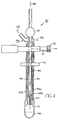
- Figures 3 and 4 show one embodiment of an accumulator 30 according to the instant invention.
- the accumulator 30 includes a central primary flow path 80 , a secondary flow path 95 , and an exit buffer gas channel 90 .
- the secondary flow path or channel 95 is positioned intermediate of the primary flow path channel 80 and the buffer exit channel 90 .
- the accumulator 30 includes a nozzle 110 at the lower end of the primary flow path. The nozzle 110 can help improve localization of the hyperpolarized gas as it impacts the cold surfaces of the reservoir 75 .
- the nozzle 110 may also allow Joule-Thompson expansion of the cooling of the gas stream to well below the freezing point of the hyperpolarized gas, advantageously minimizing the heat load on the stationary and collected hyperpolarized gas and thereby, potentially lengthening its relaxation time.
- the accumulator 30 is preferably immersed in the cryogen bath 43 such that the reservoir 75 and about 7.62-15.24 cm (3-6 inches) of the tube is immersed. If submerged in liquid nitrogen, the exterior wall of the outer sleeve 103 and the exterior wall or the reservoir 75 will be at about 77°K. The freezing point of Xenon is approximately 160°K.
- the hyperpolarized gas upon exiting the primary flow path 80 , the hyperpolarized gas hits the cold surface and freezes into the reservoir 75 while the buffer gases exit the accumulator via the exit channel 90 .
- the reservoir can include a surface coating to help prevent relaxation caused by the polarized gas's contact with same. See U.S. Patent No. 5,612,103, "Improved Coatings for the Production of Hyperpolarized Noble Gases" .
- the container can be formed from or include other materials such as high purity non-magnetic metallic films.
- the secondary flow path 95 has an inlet and outlet 125 , 126 , respectively, positioned about 180° apart at a top portion of the accumulator 30 .
- the inlet and outlet 125 , 126 are configured to be above the cryogen bath 43 or other refrigeration means when the accumulator 30 is assembled thereto.
- the secondary flow path 95 is enclosed and separate from the primary flow path 80 and the exit gas path 90 .
- the secondary flow path 95 includes a sealed closed end 96 .
- the secondary flow path 95 provides heat to a region of the accumulator 30 .
- the secondary flow path defines a heating jacket 93 .
- the heating jacket 93 is configured to provide a contained warm stream of a fluid, preferably a gas, around the primary flow path 80 . More preferably, the heating jacket 93 directs warm or ambient temperature nitrogen down the secondary flow path to an area adjacent the lower portion of the primary path 80 ; that is, the portion of the secondary path is in close proximity to or adjacent the reservoir 75 .
- the warming gas in the heating jacket 93 is directed to the nozzle 110 area of the primary flow path 80 via the secondary flow path 95 .
- such a warming gas can compensate for the undesirable tendency of this area of the primary flow path to freeze and clog due to frozen gases trapped in the flow path 80 .
- this configuration can also minimize any associated heat load which is directed into the reservoir 75 and on the collected frozen polarized gas.
- the clogging problem can be particularly troublesome in accumulators with nozzle designs, as even small amounts of build up in the reduced exit area of the nozzle 110 can block the primary flow path 80 and decrease and even prevent further collection of polarized gas.
- "Warming" as used herein can be the application of heat at any temperature above the freezing point of selected polarized gas, i.e. above 160°K for 129 Xe.
- the relaxation time of solid polarized gas (especially 129 Xe) is strongly dependent on the temperature of the frozen gas. Stated differently, the lower the temperature of the frozen gas, the longer the relaxation time. Thus, it is important to minimize the heat load on the accumulated frozen gas.
- the heat load presented by the gas stream directed down the primary flow path 80 is largely attributed to the need to cool the buffer gas from room temperature to the cryogenic temperature (as described herein liquid nitrogen (LN 2 ) or 77°K. This heat load is estimated to be on the order of 2W.
- the buffer gas is preferably cooled to just above 160°K, below which the Xe can freeze in the nozzle potentially causing a clog or blockage.
- cooling the exit gas to 160°K can cut the heat load on the frozen polarized gas by as much as 50%.
- the configuration of the instant invention allows this exit channel to be so cooled through the counter-flow of the buffer gas.
- this cooling counter-flow does not overly expose the nozzle 110 to low temperatures because the nozzle 110 or most susceptible area of the flow path 80 is separated from the exit channel by the heating jacket or secondary flow channel 95 .
- the primary flow path 80 is defined by the shape of the inner wall 93a of the heating jacket 93 .
- the inner wall 93a circumferentially extends around an opening to define the primary flow path 80 .
- the outer wall 93b of the heating jacket 93 together with the outer sleeve 103 of the accumulator 30 defines the buffer exit path 90 .
- the inner wall 93a , the outer wall 93b and the outer sleeve 103 are radially aligned.
- the inner wall of the heating jacket 93 includes a stepped down portion 193 with a diameter less than the diameter of the preceding section of the inner wall. This stepped down portion is configured to provide the nozzle 110 in the primary flow path 80.
- FIGS 5 and 7 illustrate a preferred embodiment of an accumulator 30' according to the instant invention.
- the heating jacket 93 includes at least one elongated conduit 145 which extends along a major portion of the secondary flow path 95 .
- the conduit 145 As the conduit 145 is exposed to cryogenic temperatures, it should be made from suitable substantially non-depolarizing and cryo-accepting materials such as PTFE and the like. Suitable materials include materials which have a low temperature resistance. One example of a brand of such a material is TEFLONTM or metallic-film coated surfaces.
- the conduit 145 directs the warming gas down to the lower portion of the primary flow path 80 , and more preferably directs the warming gas to the nozzle area 110 of the primary flow channel above the reservoir 75 .
- the lower end 145a of the conduit is preferably positioned adjacent the nozzle 110 .
- the warming gas travels up the circumferentially extending secondary flow path 95 and exits at the outlet vent 126 .
- This warming gas can counteract the cold/clogging effect the counter-flow of the cold buffer gas has on the primary flow path in the region susceptible to clogging as discussed above.
- additional heating jacket inlets, conduits, and vents can also be employed within the scope of the invention.
- the nozzle 110 extends along the primary flow path for about 25.4mm (1.0 inches).
- the accumulator 30 is formed from glass such as PYREXTM and is configured to withstand from about 608 - 1013.25 kPa (6-10 atm) or more of pressure.
- the warming gas is introduced into the secondary channel at a rate of about 7.8658 -47.2 ml/s (1-6 ft 3 /hour), more preferably at the rate of about 15.732-39.329 ml/s (2-5 ft 3 /hr), and still more preferably at a rate of about 23.597 ml/s (3 ft 3 /hr).
- the accumulator 30 operates at the same pressure as the optical pumping cell.
- the preferred warming gas is a dry ambient temperature N 2 (N 2 has approximately two times the heat capacity of helium), but the invention is not limited thereto.
- Exemplary preferred temperatures of the warming gas are from about 10-26.7° C (50°-80°F), and more preferably from about 20-25.6° C (68°-78°F).
- a corresponding "heating gas" flow rate is set to a minimum level corresponding to a predetermined temperature of the warming gas; i.e., the minimum rate is set for a certain temperature below which a clog occurs, this minimum rate can be termed the "critical flow rate". If higher temperatures are used, lower flow rates will typically be required.
- warming gases examples include, but are not limited to, helium, dry air, and the like.
- helium helium
- dry air a higher corresponding flow rate is used.
- lower temperature "warming” gases a higher corresponding flow rate is used.
- the instant invention can collect about 80-100% of the polarized gas in the gas stream.
- the instant invention can yield a polarized gas product with an extended useful life. This is attributed to the improved collection and/or thawing techniques which can yield a polarized gas product which retains greater polarization levels compared to conventional techniques as will be discussed further below.
- a preferred embodiment of the instant invention employs a compact permanent magnet arrangement positioned around the hyperpolarized gas.
- the magnetic field provided by such an arrangement can be somewhat inhomogeneous. As gas is thawed, this inhomogeneity can depolarize the hyperpolarized gas relatively quickly.
- Freshly thawed 129 Xe is particularly susceptible to inhomogeneity induced decay ("loss of polarization"). For example, relaxation of gaseous 129 Xe is particularly troublesome as it diffuses through inhomogeneous fields. This relaxation generally scales linearly with inverse pressure of the gas.
- the liquid 129 Xe is relatively insensitive to magnetic field gradients, inhomogeneity relaxation, temperature effects, and magnetic field strengths, thus making it one of the more robust forms of hyperpolarized 129 Xe.
- Liquid 129 Xe has typical relaxation times of about 20-30 minutes. See K.L. Sauer et al., Laser Polarized Liquid Xenon , Appl. Phys. lett. (Accepted 1997).
- the liquid state further helps to quickly distribute heat to the remaining solid 129 Xe, thus further speeding the thaw.
- the heating jacket 93 can also improve the thawing process of the frozen polarized gas. It is important to rapidly transform the frozen polarized gas into a liquid state as both the solid and the gas states of Xenon are extremely sensitive to depolarization during the transition. For example, as solid or frozen 129 Xe is warmed to near its melting point, the relaxation time is dramatically reduced from 3 hours at 77°K to just a few seconds near the phase transition point. In addition, gaseous relaxation at temperatures just above the sublimation temperature of 129 Xe is rapid, with an exponential dependence on temperature. For example, the relaxation time of gaseous 129 Xe on a given surface at 160°K is only 3% as long as that at 300°K on the same surface. Further, during the early stages of thawing when the Xe gas pressure is low, the gaseous 129 Xe is more susceptible to the inhomogeneity problems discussed above.
- the heating jacket 93 of the accumulator 30 , 30' described above can additionally improve the thawing process.
- the heating jacket or secondary flow channel 95 of the accumulator can supply heat to the nozzle area 110 of the accumulator 30 during the thawing process.
- the lower area of the flow path or the nozzle area is preheated before thawing so that the nozzle 110 is well above the freezing point of the polarized gas prior to applying heat to the external surface of the reservoir 75 .
- heat is supplied to both the exterior and the interior of the cold finger.
- the interior heating being preferably applied to the lower region of the accumulator, i.e., the nozzle area.
- the nozzle 110 is thus warmed by the circulating fluid (preferably gas) in the heating jacket 93 .
- Various warming gases such as those described above can be used.
- the flow rate of the warming gas is higher than that used during the accumulation process, such as about 39.329 - 94.39 ml/s (5-12 ft 3 /hr), and more preferably at about 78.658 ml/s (10 ft 3 /hr) during thaw.
- the preferred temperatures of the "warming" gas supplied during thawing are at typical internally controlled ambient conditions (for example room temperature gases such as 20-25.6°C (68-78°F)).
- the isolation valve 35 is preferably opened leading to an attached evacuated chamber or bag or other delivery means or collection vessel.
- the valves 35 , 37 can be opened depending on where the delivery vessel or receptacle is attached (not shown).
- isolation valve 37 is the operative valve as described above. The sudden decrease in pressure causes the liquid 129 Xe to become gaseous and exit the accumulator 30 rapidly, advantageously thereby spending a minimum amount of time in the inhomogeneous magnetic field in the gaseous state.
- the isolation valve 37 is opened and the gas flows through valve 47 and exits outlet 50 into a delivery vessel.
- Conventional methods of thawing included opening the cold finger (accumulator) to the vessel to be filled and then starting the thaw. This thaw could typically take 30 seconds or more to complete for single patient dose amounts.
- the instant thaw method can be completed in less than about 10 seconds, and preferably in less than about 5-6 seconds for single dose amounts of frozen hyperpolarized gas.
- a typical patient dose is from about 0.20-1.25 liters ("L") and preferably about 0.5-1.0 L.
- the conversion weight is about 5.4 grams /L of Xe.
- the density of solid Xe is about 3.1g/cm 3
- a corresponding patient volume of polarized frozen Xe can be calculated at about 1.8cm 3 /L.
- observations of the instant thawing method indicate a reliable factor of about 2 or more improvement in the final polarization level of thawed 129 Xe as compared to that thawed by conventional methods.
- Figure 12A illustrates the polarization results obtained by a conventional thaw technique while Figure 12B graphically illustrates results obtained by the improved thaw method as described above.
- Each of the graphs plot % polarization of 129 Xe after thaw in relationship to the total gas flow rate through the polarization cell 22 (and therefore the entire unit).
- the corresponding 129 Xe flow rate is the % of the total gas mix.
- 129 Xe makes up about 1% of the total gas mix, thus the 129 Xe-flow rate is the total flow rate divided by 100.
- 129 Xe is typically accumulated at the rate of 10 cm 3 per min or 600 cm 3 per hour.
- Higher flow rates are desired to increase the through-put of 129 Xe.
- polarization is reduced at higher flow rates. This is attributed to the reduced time that the 129 Xe spends in residence time in spin exchange contact with the optically pumped Rb at higher flow rates. That is, the Xe residence time in the cell 22 can generally be described mathematically as equal to the gas pressure multiplied by the cell volume divided by the flow rate ( PV / m ).
- Figure 12A shows the conventional thaw technique yields scattered polarization results which are attributed to random polarization losses mainly occurring during thawing.
- Figure 12B tracks with the optical pumping characteristics described above and now produces predictable post-thaw polarization levels corresponding to the accumulation flow rate.
- the associated polarization curve will drop below the values shown relative to that for an exemplary 190 cm 3 volume of polarized gas as shown in Figure 12B.
- larger amounts of polarized gas can result in a larger loss attributed to solid-phase relaxation.
- frozen gas thaw method which results in a post-thaw polarization curve which predictably follows the initial polarization curve.
- Figure 12A the conventional polarization level after thaw is highly unpredictable, with an average of about 4.4%.
- the method produces polarization levels after thaw that predictably corresponds to the flow rate used during accumulation.
- Figure 13 illustrates experimental and theoretical polarization levels before and after thawing.
- the experimental flowing curve shows the polarization levels achieved before freezing (the level measured as the 129 Xe exits the pumping cell 22 ).
- the experimental data points on the graph represent thawed data points achieved by thawing the collected, frozen polarized gas according to the present invention.
- the experimental data confirms that the methods improve the predictability of the polarization retention fraction now achievable as well as increases the value of the polarization retention fraction (amount of polarization retained post-thaw relative to that attained prior to freeze).
- Figure 13A illustrates a flow curve used to predict polarization levels as expected from a thawed polarized xenon product, this curve representing post-thaw polarization levels achievable absent polarization losses during freezing and thawing.
- This curve includes losses from normal relaxation of solid Xe (which can be generally estimated to be approximately 2 hours at 77°K).
- low flow rates typically have an associated relatively large polarization loss. This is because, at low flow rates, the accumulation time can be extensive and the ice "T1" then plays a larger or more dominant role.
- the polarization retention fraction achieved using the freezing and thawing methods is above 40% for all flow rates, and the average is about 49.9%.
- a data point at a flow rate of 600 sccm has a theoretical polarization level of 22.1 and a corresponding experimental data point of 11.18 polarization after thaw.
- the initial polarization level (before- accumulation/freezing) for this flow rate is 22.1%. Therefore, the polarization retention fraction after the freeze/thaw process is 11.18/22.1 or 50.6%.
- the instant thawing technique retains at least 30% of the initial polarization level and based on this data preferably above 40% of the initial polarization level, and most preferably above 45%. Further the improved retention rate increases the thawed polarization level by an order of magnitude (now reliably and predictably above about 10% in contrast to conventional thawed polarization levels of about 2%).
- cryogen used to freeze the polarized gas is not limited to liquid N 2 .
- flow rates, accumulation rates, "warming" gas temperatures and the like should be adjusted accordingly.
- polarized gases frozen at liquid nitrogen temperatures have an ice relaxation time (T1) of approximately 2.8 hours while polarized gases frozen at liquid helium temperatures have an ice relaxation time (T1) of approximately 12 days. Therefore, in order to achieve higher polarization levels after thawing, the thawing is preferably performed within the corresponding T1 time period.
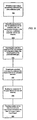
- FIGS 9, 10, and 11 are block diagrams of methods associated with the instant invention. The order of the methods is not meant to be limited by the block numbers and order shown. Additional steps can also be included as operationally described hereinabove.
- FIG. 9 shows steps for accumulating or collecting frozen polarized gas according to one embodiment of the instant invention
- a gas mixture comprising a polarized gas is directed into collection path ( Block 900 ).
- the polarized gas is received into the accumulator in the collection path.
- the accumulator has an inlet channel, a collection reservoir, and an exit channel ( Block 910 ).
- the collection reservoir is exposed to temperatures below the freezing point of the polarized noble gas ( Block 920 ).
- the polarized gas is trapped in a substantially frozen state in the collection reservoir (preferably a total solid frozen state)( Block 930 ).
- the remainder of the gas mixture is routed into the exit channel ( Block 940 ).
- a portion of the inlet channel in the accumulator is heated to facilitate the flow of the gas mixture therethrough ( Block 950 ).
- the heating step ( Block 950 ) is preferably carried out by introducing a gas separate from the gas mixture to conductively heat a predetermined area of the inlet channel, the separate gas being contained apart from the inlet and exit paths. The contained separate gas is then circulated about a portion of the inlet path to reduce the likelihood of blockage along the inlet path attributed to the exposing step.
- FIG. 10 illustrates a method for thawing frozen polarized gas.
- a sealed container is provided which includes an interior flow path and a collection chamber for holding frozen polarized gas ( Block 1000 ).
- the frozen gas is exposed to a magnetic field ( Block 1005 ).
- a portion of the interior flow path adjacent the collection chamber is heated ( Block 1010 ).
- the exterior of the sealed container is also heated ( Block 1020 ).
- the frozen gas is liquefied during the heating steps such that a minimum amount of the polarized gas transitions to the gaseous phase (and conversely, a substantial amount of the polarized gas transitions directly to the liquid phase) ( Block 1030 ).
- the liquefying step is carried out by closing the isolation valves and sealing the container allowing the pressure to build to a predetermined level, the level corresponding to the time it takes to provide an "instantaneous" thaw.
- the valves remain closed for as short a period as possible (as described above, less than about 10 seconds for a single patient dose), the period corresponding to the time it takes to achieve substantially full gas pressure upon opening the accumulator isolation valve.
- the release pressure can be calculated according to a liquid Xe vapor pressure curve. See V.A. Rabinovich et al., Thermophysical Properties of Neon, Argon, Krypton, and Xenon (Hemisphere Publishing Corp., Wash, 1988).
- An exemplary pressure release is thought to be less than approximately 506.625-1013.25 kPa (5-10 atm) (and at least less than about 1722.525 kPa (17 atm)) for a 0.5L accumulation in a 30cm 3 accumulator at a temperature below 200K. This value will be different for different cold finger volumes, different accumulation volumes, and the temperature of the gas in liquid Xe.
- the gas pressure is released from the sealed container as soon as the liquid state is achieved. It is also preferred that the interior be heated as described above.
- Figure 11 illustrates a method for extending the useful polarization life of a polarized gas product.
- a magnetic field is provided (Block 1100).
- the polarized gas product is frozen in the presence of the magnetic field ( Block 1110) .
- a quantity of the frozen polarized gas is sealed in a containment device ( Block 1115 ).
- the polarized gas is thawed in the presence of a magnetic field (Block 1120).
- a substantial quantity of the frozen gas is converted directly into the liquid phase in the sealed container during the thawing step ( Block 1130 ).
- various other steps can be employed along the lines described hereinabove.
- steps can include, but are not limited to, decreasing the amount of 131 Xe in the enriched gas mixture, heating the interior of the flow path, using a nozzle to direct the flow of gas, depressurizing the containment device by opening the valves causing the liquid to become gas and releasing the polarized gas to a interface such as a bag or other delivery device).
Landscapes
- Chemical & Material Sciences (AREA)
- Physics & Mathematics (AREA)
- Health & Medical Sciences (AREA)
- Engineering & Computer Science (AREA)
- Nuclear Medicine, Radiotherapy & Molecular Imaging (AREA)
- Life Sciences & Earth Sciences (AREA)
- Organic Chemistry (AREA)
- Chemical Kinetics & Catalysis (AREA)
- Dispersion Chemistry (AREA)
- Thermal Sciences (AREA)
- Mechanical Engineering (AREA)
- Radiology & Medical Imaging (AREA)
- Epidemiology (AREA)
- General Engineering & Computer Science (AREA)
- Animal Behavior & Ethology (AREA)
- General Health & Medical Sciences (AREA)
- Public Health (AREA)
- Veterinary Medicine (AREA)
- Condensed Matter Physics & Semiconductors (AREA)
- General Physics & Mathematics (AREA)
- Magnetic Resonance Imaging Apparatus (AREA)
- Devices That Are Associated With Refrigeration Equipment (AREA)
Description
| Isotope | Abundance | Nuclear Spin |
| 124Xe | 0.1% | 0 |
| 126Xe | 0.09% | 0 |
| 128Xe | 1.91% | 0 |
| 129Xe | 26.4% | ½ |
| 130Xe | 4.1% | 0 |
| 131Xe | 21.2% | 3/2 |
| 132Xe | 26.9% | 0 |
| 134Xe | 10.4% | 0 |
| 136Xe | 8.9% | 0 |
| Isotope | Abundance | Nuclear Spin |
| 124Xe | 0.47% | 0 |
| 126Xe | 0.43% | 0 |
| 128Xe | 8.41% | 0 |
| 129Xe | 82.3% | ½ |
| 130Xe | 4.52% | 0 |
| 131Xe | 3.45% | 3/2 |
| 132Xe | 0.36% | 0 |
| 134Xe | 0.01% | 0 |
| 136Xe | 0.01% | 0 |
| Isotope | Abundance | Nuclear Spin |
| 124Xe | 0.14% | 0 |
| 126Xe | 0.28% | 0 |
| 128Xe | 52.0% | 0 |
| 129Xe | 47.2% | ½ |
| 130Xe | 0.22% | 0 |
| 131Xe | 0.09% | 3/2 |
| 132Xe | 0.03% | 0 |
| 134Xe | 0.02% | 0 |
| 136Xe | 0.02% | 0 |
| Flow Rate | Polarization (P) theory | Pexper. | Retention Fraction |
| 300 | 24 | 12.66 | 52.8% |
| 600 | 22.1 | 11.18 | 50.6% |
| 900 | 18.7 | 9.30 | 49.7% |
| 1200 | 15.9 | 7.83 | 49.2% |
| 1500 | 13.75 | 6.73 | 48.9% |
| 1800 | 12.08 | 5.90 | 48.8% |
| 2000 | 11.1 | 5.43 | 48.9% |
Claims (29)
- A cryogenic accumulator 30 for collecting frozen polarized noble gases, comprising:a primary flow channel 80 having opposing first and second ends configured to direct polarized gas therethrough;an outer sleeve positioned 103 around said primary flow channel 80, said outer sleeve 103 having a closed end defining a collection chamber 75 positioned below said primary flow channel 80 second end; anda secondary flow channel 95 positioned intermediate of said primary flow channel 80 and said outer sleeve 103, said secondary flow channel 95 having a closed end positioned in close proximity to said primary flow channel second end.
- A cryogenic accumulator 30 according to Claim 1, said secondary flow channel 95 having a cylindrically shaped inner wall 93a, wherein said inner wall 93a defines said primary flow channel 80.
- A cryogenic accumulator 30 according to Claim 1 or 2, said secondary flow channel 95 having an outer wall 93b, wherein said outer wall 93b and said outer sleeve 103 define a buffer gas exit channel 90 therebetween.
- A cryogenic accumulator 30 according to any of Claims 1 to 3, wherein said primary flow channel second end is a nozzle 110.
- A cryogenic accumulator 30 according to Claim 3, further comprising first and second isolation valves 35, 37 in communication with said primary flow channel 80 and said buffer gas exit channel 90.
- A cryogenic accumulator 30 according to Claim 5, wherein said first isolation valve 35 is positioned at the first end of said primary flow channel to control the flow of a target gas therethrough.
- A cryogenic accumulator 30 according to Claim 5, wherein said second isolation valve 37 is positioned spaced-apart from said outer sleeve 103 closed end along said buffer gas exit channel 90 to releasably seal and control the release of gas therethrough.
- A cryogenic accumulator 30 according to any of Claims 1 to 7, further comprising a secondary flow channel inlet 125 and vent port 126, and a conduit 145 in fluid communication with said inlet 125, wherein said conduit 145 extends along a major portion of said secondary flow channel 95 to thereby direct the flow of a warming gas to a predetermined area of said primary flow channel 80.
- A cryogenic accumulator 30 according to any of Claims 1 to 8, in combination with a hyperpolarizer unit 10, wherein said accumulator 30 is configured to detachably release from said hyperpolarizer unit 10.
- A cryogenic accumulator 30 according to any of Claims 1 to 9, wherein said secondary flow channel 95 is separate from said primary flow channel 80.
- A cryogenic accumulator 30 according to any of Claims 1 to 10, wherein said secondary flow channel 95 is a heating jacket 93 configured to circulate a gas therethrough.
- A cryogenic accumulator 30 according to any of Claims 1 to 11, wherein said secondary flow channel 95 includes a longitudinally extending conduit 145 configured to direct a gas to said secondary flow channel 95 closed end adjacent said second end of said primary flow channel 80.
- A cryogenic accumulator 30 according to any of Claims 1 to 12, further comprising at least one permanent field magnet 40 positioned adjacent said collection chamber 75.
- A cryogenic accumulator 30 according to any of Claims 1 to 13, further comprising a cryogenic refrigeration source 42 operably associated with said collection chamber 75.
- A cryogenic accumulator 30 according to any of Claims 1 to 14, wherein said secondary flow channel 95 is configured to circulate ambient temperature gaseous nitrogen therethrough.
- A cryogenic accumulator 30 according to any of Claims 1 to 15, said accumulator 30 further comprising at least one secondary flow channel vent 126 in communication with said secondary flow channel 95.
- A cryogenic accumulator 30 according to Claim 16, further comprising a flow adjustment valve operably associated with said vent 126 to adjust the flow of a gas therein thereby adjusting the heat supplied to at least a portion of said primary flow channel 80.
- A cryogenic accumulator 30 according to any of Claims 1 to 17, wherein said outer sleeve 103, said secondary flow channel 95, and said primary flow channel 80 are radially aligned along a major portion of the length of said accumulator 30.
- A cryogenic accumulator according to any of Claims 1 to 18, wherein said second end is configured as a flow nozzle 110, and wherein said flow nozzle 110 is aligned with and positioned adjacent to said collection chamber 75.
- A cryogenic accumulator 30 according to Claim 19, further comprising a heat source 93 positioned intermediate of said primary flow channel 80 and said outer sleeve 103 before said collection chamber 75, said heat source arranged to provide heat to said flow nozzle 110.
- A cryogenic accumulator 30 according to Claim 20, wherein said heat source 93 includes a conduit 145 for directing a flow of a predetermined gas to said flow nozzle 110.
- A method for collecting frozen noble polarised gas, comprising the steps of:directing a gas mixture comprising a polarized noble gas and a second gas along a collection path and into an accumulator 30;receiving the gas mixture into the accumulator 30 positioned in the collection path, the accumulator having an inlet channel 80, a collection reservoir 75, and an exit channel 90;cooling the collection reservoir 75 to temperatures below the freezing point of the polarized noble gas;capturing polarized noble gas in a substantially frozen state 100 in the collection reservoir 75;passing the remainder of the gas mixture including the second gas into the exit channel 90; andheating a portion of the inlet channel 80 in the accumulator 30 to facilitate the flow of the gas mixture therethrough.
- A method according to Claim 22, wherein said heating step comprises the steps of:introducing a gas separate from the gas mixture to heat a predetermined area of the inlet channel 80, the separate gas being contained apart 95 from the inlet 80 and exit paths 90, and the collection reservoir 75;circulating the gas separate from the gas mixture about a portion of the inlet path 80 to provide conductive heat to selected portions of the inlet path 80 and reduce the likelihood of blockage along the inlet path 80 attributed to said cooling step.
- A method according to Claim 22 or Claim 23, wherein said directing step includes flowing the gas mixture through a directional nozzle 110 into the collection reservoir 75.
- A method according to any of Claims 22 to 24, wherein said cooling step includes immersing the bottom reservoir 75 into a liquid cryogen bath 43.
- A method according to any of Claims 22 to 25, wherein said heating step is provided by the steps of:circulating room temperature nitrogen gas around the outside of at least a portion of the inlet channel 80; andcapturing the nitrogen gas and venting it to atmosphere away from the frozen accumulated noble gas 100.
- A method according to any of Claims 22 to 26, further comprising the steps of:accumulating polarized noble gas 100 in the collection reservoir 75; andexposing the gas to a magnetic field during accumulation.
- A method according to Claim 27, further comprising the steps of:detaching the accumulator 30 from a portion of the collection path andtransporting the accumulator 30 with frozen polarized gas 100 in the presence of a magnetic field to a remote site.
- A method according to any of Claims 22 to 28, wherein said polarized gas is 129Xe.
Applications Claiming Priority (3)
| Application Number | Priority Date | Filing Date | Title |
|---|---|---|---|
| US6943597P | 1997-12-12 | 1997-12-12 | |
| US69435P | 1997-12-12 | ||
| EP98967030A EP1051602B1 (en) | 1997-12-12 | 1998-12-11 | Process to solidify and thaw a polarized gas comprising xenon |
Related Parent Applications (2)
| Application Number | Title | Priority Date | Filing Date |
|---|---|---|---|
| EP98967030.2 Division | 1998-12-11 | ||
| EP98967030A Division EP1051602B1 (en) | 1997-12-12 | 1998-12-11 | Process to solidify and thaw a polarized gas comprising xenon |
Publications (3)
| Publication Number | Publication Date |
|---|---|
| EP1279912A2 EP1279912A2 (en) | 2003-01-29 |
| EP1279912A3 EP1279912A3 (en) | 2003-02-26 |
| EP1279912B1 true EP1279912B1 (en) | 2005-03-02 |
Family
ID=26152839
Family Applications (1)
| Application Number | Title | Priority Date | Filing Date |
|---|---|---|---|
| EP02022943A Expired - Lifetime EP1279912B1 (en) | 1997-12-12 | 1998-12-11 | Methods of collecting and thawing polarised gases, associated accumulators and heating jackets |
Country Status (2)
| Country | Link |
|---|---|
| EP (1) | EP1279912B1 (en) |
| DK (1) | DK1279912T3 (en) |
Family Cites Families (2)
| Publication number | Priority date | Publication date | Assignee | Title |
|---|---|---|---|---|
| US5545396A (en) * | 1994-04-08 | 1996-08-13 | The Research Foundation Of State University Of New York | Magnetic resonance imaging using hyperpolarized noble gases |
| US5642625A (en) * | 1996-03-29 | 1997-07-01 | The Trustees Of Princeton University | High volume hyperpolarizer for spin-polarized noble gas |
-
1998
- 1998-12-11 DK DK02022943T patent/DK1279912T3/en active
- 1998-12-11 EP EP02022943A patent/EP1279912B1/en not_active Expired - Lifetime
Also Published As
| Publication number | Publication date |
|---|---|
| EP1279912A2 (en) | 2003-01-29 |
| EP1279912A3 (en) | 2003-02-26 |
| DK1279912T3 (en) | 2005-06-06 |
Similar Documents
| Publication | Publication Date | Title |
|---|---|---|
| US6305190B1 (en) | Polarized gas accumulators and heating jackets and associated gas collection methods and thaw methods and polarized gas products | |
| US6079213A (en) | Methods of collecting, thawing, and extending the useful life of polarized gases and associated accumulators and heating jackets | |
| JP2002500337A5 (en) | ||
| JP4231533B2 (en) | Low temperature accumulator for spin polarized xenon-129 | |
| CA2250168C (en) | High volume hyperpolarizer for spin-polarized noble gas | |
| US7495435B2 (en) | Method for the hyperpolarisation of atomic nuclei and device for implementing the method | |
| WO1999034189A2 (en) | Process and device to solidify and thaw a polarized gas comprising xenon | |
| EP1588178B1 (en) | Method of producing optically pumped hyperpolarized gas | |
| AU2003203796B2 (en) | Polarized gas accumulators and heating jackets and associated gas collection and thaw methods and polarized gas products | |
| EP1279912A2 (en) | Methods of collecting and thawing polarised gases, associated accumulators and heating jackets | |
| CA2602360A1 (en) | Collection and accumulation of frozen polarized gases | |
| US20260118452A1 (en) | Hyperpolarizers with a load-lock chamber for alkali metal | |
| CA2349069C (en) | Cryogenic accumulator for spin-polarized xenon-129 |
Legal Events
| Date | Code | Title | Description |
|---|---|---|---|
| PUAI | Public reference made under article 153(3) epc to a published international application that has entered the european phase |
Free format text: ORIGINAL CODE: 0009012 |
|
| PUAL | Search report despatched |
Free format text: ORIGINAL CODE: 0009013 |
|
| 17P | Request for examination filed |
Effective date: 20021011 |
|
| AC | Divisional application: reference to earlier application |
Ref document number: 1051602 Country of ref document: EP Kind code of ref document: P |
|
| AK | Designated contracting states |
Designated state(s): AT BE CH CY DE DK ES FI FR GB GR IE IT LI LU MC NL PT SE |
|
| AK | Designated contracting states |
Designated state(s): AT BE CH CY DE DK ES FI FR GB GR IE IT LI LU MC NL PT SE Kind code of ref document: A3 Designated state(s): AT BE CH CY DE DK ES FI FR GB GR IE IT LI LU MC NL PT SE |
|
| AKX | Designation fees paid |
Designated state(s): AT BE CH CY DE DK ES FI FR GB GR IE IT LI LU MC NL PT SE |
|
| 17Q | First examination report despatched |
Effective date: 20031127 |
|
| GRAP | Despatch of communication of intention to grant a patent |
Free format text: ORIGINAL CODE: EPIDOSNIGR1 |
|
| GRAS | Grant fee paid |
Free format text: ORIGINAL CODE: EPIDOSNIGR3 |
|
| GRAA | (expected) grant |
Free format text: ORIGINAL CODE: 0009210 |
|
| AC | Divisional application: reference to earlier application |
Ref document number: 1051602 Country of ref document: EP Kind code of ref document: P |
|
| AK | Designated contracting states |
Kind code of ref document: B1 Designated state(s): AT BE CH CY DE DK ES FI FR GB GR IE IT LI LU MC NL PT SE |
|
| PG25 | Lapsed in a contracting state [announced via postgrant information from national office to epo] |
Ref country code: FR Free format text: LAPSE BECAUSE OF NON-PAYMENT OF DUE FEES Effective date: 20050302 |
|
| REG | Reference to a national code |
Ref country code: GB Ref legal event code: FG4D |
|
| REG | Reference to a national code |
Ref country code: CH Ref legal event code: EP |
|
| REG | Reference to a national code |
Ref country code: IE Ref legal event code: FG4D |
|
| REF | Corresponds to: |
Ref document number: 69829231 Country of ref document: DE Date of ref document: 20050407 Kind code of ref document: P |
|
| PG25 | Lapsed in a contracting state [announced via postgrant information from national office to epo] |
Ref country code: GR Free format text: LAPSE BECAUSE OF FAILURE TO SUBMIT A TRANSLATION OF THE DESCRIPTION OR TO PAY THE FEE WITHIN THE PRESCRIBED TIME-LIMIT Effective date: 20050602 |
|
| REG | Reference to a national code |
Ref country code: DK Ref legal event code: T3 |
|
| REG | Reference to a national code |
Ref country code: SE Ref legal event code: TRGR |
|
| REG | Reference to a national code |
Ref country code: CH Ref legal event code: NV Representative=s name: ISLER & PEDRAZZINI AG |
|
| PG25 | Lapsed in a contracting state [announced via postgrant information from national office to epo] |
Ref country code: PT Free format text: LAPSE BECAUSE OF FAILURE TO SUBMIT A TRANSLATION OF THE DESCRIPTION OR TO PAY THE FEE WITHIN THE PRESCRIBED TIME-LIMIT Effective date: 20050907 |
|
| REG | Reference to a national code |
Ref country code: ES Ref legal event code: FG2A Ref document number: 2239192 Country of ref document: ES Kind code of ref document: T3 |
|
| PG25 | Lapsed in a contracting state [announced via postgrant information from national office to epo] |
Ref country code: CY Free format text: LAPSE BECAUSE OF FAILURE TO SUBMIT A TRANSLATION OF THE DESCRIPTION OR TO PAY THE FEE WITHIN THE PRESCRIBED TIME-LIMIT Effective date: 20051211 |
|
| PGFP | Annual fee paid to national office [announced via postgrant information from national office to epo] |
Ref country code: FR Payment date: 20051216 Year of fee payment: 8 |
|
| PG25 | Lapsed in a contracting state [announced via postgrant information from national office to epo] |
Ref country code: MC Free format text: LAPSE BECAUSE OF NON-PAYMENT OF DUE FEES Effective date: 20051231 Ref country code: LU Free format text: LAPSE BECAUSE OF NON-PAYMENT OF DUE FEES Effective date: 20051231 |
|
| PLBE | No opposition filed within time limit |
Free format text: ORIGINAL CODE: 0009261 |
|
| STAA | Information on the status of an ep patent application or granted ep patent |
Free format text: STATUS: NO OPPOSITION FILED WITHIN TIME LIMIT |
|
| 26N | No opposition filed |
Effective date: 20051205 |
|
| EN | Fr: translation not filed | ||
| REG | Reference to a national code |
Ref country code: CH Ref legal event code: PCAR Free format text: ISLER & PEDRAZZINI AG;POSTFACH 1772;8027 ZUERICH (CH) |
|
| PGFP | Annual fee paid to national office [announced via postgrant information from national office to epo] |
Ref country code: DK Payment date: 20101228 Year of fee payment: 13 Ref country code: AT Payment date: 20101119 Year of fee payment: 13 |
|
| PGFP | Annual fee paid to national office [announced via postgrant information from national office to epo] |
Ref country code: IT Payment date: 20101227 Year of fee payment: 13 Ref country code: GB Payment date: 20101229 Year of fee payment: 13 |
|
| PGFP | Annual fee paid to national office [announced via postgrant information from national office to epo] |
Ref country code: SE Payment date: 20111229 Year of fee payment: 14 Ref country code: CH Payment date: 20111227 Year of fee payment: 14 Ref country code: FI Payment date: 20111229 Year of fee payment: 14 Ref country code: IE Payment date: 20111227 Year of fee payment: 14 Ref country code: ES Payment date: 20111226 Year of fee payment: 14 |
|
| PGFP | Annual fee paid to national office [announced via postgrant information from national office to epo] |
Ref country code: BE Payment date: 20111227 Year of fee payment: 14 |
|
| PGFP | Annual fee paid to national office [announced via postgrant information from national office to epo] |
Ref country code: DE Payment date: 20111229 Year of fee payment: 14 |
|
| PGFP | Annual fee paid to national office [announced via postgrant information from national office to epo] |
Ref country code: NL Payment date: 20120103 Year of fee payment: 14 |
|
| REG | Reference to a national code |
Ref country code: DE Ref legal event code: R082 Ref document number: 69829231 Country of ref document: DE Representative=s name: J D REYNOLDS & CO., GB |
|
| BERE | Be: lapsed |
Owner name: *MEDI-PHYSICS INC. Effective date: 20121231 |
|
| REG | Reference to a national code |
Ref country code: NL Ref legal event code: V1 Effective date: 20130701 |
|
| PG25 | Lapsed in a contracting state [announced via postgrant information from national office to epo] |
Ref country code: SE Free format text: LAPSE BECAUSE OF NON-PAYMENT OF DUE FEES Effective date: 20121212 |
|
| REG | Reference to a national code |
Ref country code: CH Ref legal event code: PL |
|
| REG | Reference to a national code |
Ref country code: AT Ref legal event code: MM01 Ref document number: 290194 Country of ref document: AT Kind code of ref document: T Effective date: 20121211 |
|
| REG | Reference to a national code |
Ref country code: DK Ref legal event code: EBP |
|
| GBPC | Gb: european patent ceased through non-payment of renewal fee |
Effective date: 20121211 |
|
| PG25 | Lapsed in a contracting state [announced via postgrant information from national office to epo] |
Ref country code: FI Free format text: LAPSE BECAUSE OF NON-PAYMENT OF DUE FEES Effective date: 20121211 |
|
| REG | Reference to a national code |
Ref country code: IE Ref legal event code: MM4A |
|
| PG25 | Lapsed in a contracting state [announced via postgrant information from national office to epo] |
Ref country code: BE Free format text: LAPSE BECAUSE OF NON-PAYMENT OF DUE FEES Effective date: 20121231 |
|
| REG | Reference to a national code |
Ref country code: DE Ref legal event code: R119 Ref document number: 69829231 Country of ref document: DE Effective date: 20130702 |
|
| PG25 | Lapsed in a contracting state [announced via postgrant information from national office to epo] |
Ref country code: DE Free format text: LAPSE BECAUSE OF NON-PAYMENT OF DUE FEES Effective date: 20130702 Ref country code: NL Free format text: LAPSE BECAUSE OF NON-PAYMENT OF DUE FEES Effective date: 20130701 Ref country code: LI Free format text: LAPSE BECAUSE OF NON-PAYMENT OF DUE FEES Effective date: 20121231 Ref country code: CH Free format text: LAPSE BECAUSE OF NON-PAYMENT OF DUE FEES Effective date: 20121231 Ref country code: AT Free format text: LAPSE BECAUSE OF NON-PAYMENT OF DUE FEES Effective date: 20121211 Ref country code: IE Free format text: LAPSE BECAUSE OF NON-PAYMENT OF DUE FEES Effective date: 20121211 |
|
| PG25 | Lapsed in a contracting state [announced via postgrant information from national office to epo] |
Ref country code: GB Free format text: LAPSE BECAUSE OF NON-PAYMENT OF DUE FEES Effective date: 20121211 |
|
| PG25 | Lapsed in a contracting state [announced via postgrant information from national office to epo] |
Ref country code: IT Free format text: LAPSE BECAUSE OF NON-PAYMENT OF DUE FEES Effective date: 20121211 |
|
| PG25 | Lapsed in a contracting state [announced via postgrant information from national office to epo] |
Ref country code: DK Free format text: LAPSE BECAUSE OF NON-PAYMENT OF DUE FEES Effective date: 20130102 |
|
| REG | Reference to a national code |
Ref country code: ES Ref legal event code: FD2A Effective date: 20140307 |
|
| PG25 | Lapsed in a contracting state [announced via postgrant information from national office to epo] |
Ref country code: ES Free format text: LAPSE BECAUSE OF NON-PAYMENT OF DUE FEES Effective date: 20121212 |