EP1279563B1 - Motor vehicle brake or clutch pedal - Google Patents
Motor vehicle brake or clutch pedal Download PDFInfo
- Publication number
- EP1279563B1 EP1279563B1 EP02077847A EP02077847A EP1279563B1 EP 1279563 B1 EP1279563 B1 EP 1279563B1 EP 02077847 A EP02077847 A EP 02077847A EP 02077847 A EP02077847 A EP 02077847A EP 1279563 B1 EP1279563 B1 EP 1279563B1
- Authority
- EP
- European Patent Office
- Prior art keywords
- blade part
- pedal
- blade
- release lever
- component
- Prior art date
- Legal status (The legal status is an assumption and is not a legal conclusion. Google has not performed a legal analysis and makes no representation as to the accuracy of the status listed.)
- Expired - Lifetime
Links
- 230000005540 biological transmission Effects 0.000 description 2
- 238000010168 coupling process Methods 0.000 description 2
- 238000005859 coupling reaction Methods 0.000 description 2
- 206010061225 Limb injury Diseases 0.000 description 1
- 208000027418 Wounds and injury Diseases 0.000 description 1
- 238000010276 construction Methods 0.000 description 1
- 230000006378 damage Effects 0.000 description 1
- 208000014674 injury Diseases 0.000 description 1
- 230000003993 interaction Effects 0.000 description 1
- 210000003141 lower extremity Anatomy 0.000 description 1
Images



Classifications
-
- G—PHYSICS
- G05—CONTROLLING; REGULATING
- G05G—CONTROL DEVICES OR SYSTEMS INSOFAR AS CHARACTERISED BY MECHANICAL FEATURES ONLY
- G05G1/00—Controlling members, e.g. knobs or handles; Assemblies or arrangements thereof; Indicating position of controlling members
- G05G1/30—Controlling members actuated by foot
- G05G1/32—Controlling members actuated by foot with means to prevent injury
- G05G1/327—Controlling members actuated by foot with means to prevent injury means disconnecting the pedal from its hinge or support, e.g. by breaking or bending the support
-
- B—PERFORMING OPERATIONS; TRANSPORTING
- B60—VEHICLES IN GENERAL
- B60R—VEHICLES, VEHICLE FITTINGS, OR VEHICLE PARTS, NOT OTHERWISE PROVIDED FOR
- B60R21/00—Arrangements or fittings on vehicles for protecting or preventing injuries to occupants or pedestrians in case of accidents or other traffic risks
- B60R21/02—Occupant safety arrangements or fittings, e.g. crash pads
- B60R21/09—Control elements or operating handles movable from an operative to an out-of-the way position, e.g. pedals, switch knobs, window cranks
-
- B—PERFORMING OPERATIONS; TRANSPORTING
- B60—VEHICLES IN GENERAL
- B60T—VEHICLE BRAKE CONTROL SYSTEMS OR PARTS THEREOF; BRAKE CONTROL SYSTEMS OR PARTS THEREOF, IN GENERAL; ARRANGEMENT OF BRAKING ELEMENTS ON VEHICLES IN GENERAL; PORTABLE DEVICES FOR PREVENTING UNWANTED MOVEMENT OF VEHICLES; VEHICLE MODIFICATIONS TO FACILITATE COOLING OF BRAKES
- B60T7/00—Brake-action initiating means
- B60T7/02—Brake-action initiating means for personal initiation
- B60T7/04—Brake-action initiating means for personal initiation foot actuated
- B60T7/06—Disposition of pedal
- B60T7/065—Disposition of pedal with means to prevent injuries in case of collision
-
- Y—GENERAL TAGGING OF NEW TECHNOLOGICAL DEVELOPMENTS; GENERAL TAGGING OF CROSS-SECTIONAL TECHNOLOGIES SPANNING OVER SEVERAL SECTIONS OF THE IPC; TECHNICAL SUBJECTS COVERED BY FORMER USPC CROSS-REFERENCE ART COLLECTIONS [XRACs] AND DIGESTS
- Y10—TECHNICAL SUBJECTS COVERED BY FORMER USPC
- Y10T—TECHNICAL SUBJECTS COVERED BY FORMER US CLASSIFICATION
- Y10T74/00—Machine element or mechanism
- Y10T74/20—Control lever and linkage systems
- Y10T74/20528—Foot operated
-
- Y—GENERAL TAGGING OF NEW TECHNOLOGICAL DEVELOPMENTS; GENERAL TAGGING OF CROSS-SECTIONAL TECHNOLOGIES SPANNING OVER SEVERAL SECTIONS OF THE IPC; TECHNICAL SUBJECTS COVERED BY FORMER USPC CROSS-REFERENCE ART COLLECTIONS [XRACs] AND DIGESTS
- Y10—TECHNICAL SUBJECTS COVERED BY FORMER USPC
- Y10T—TECHNICAL SUBJECTS COVERED BY FORMER US CLASSIFICATION
- Y10T74/00—Machine element or mechanism
- Y10T74/20—Control lever and linkage systems
- Y10T74/20576—Elements
- Y10T74/20888—Pedals
Definitions
- This invention relates to a motor vehicle brake or clutch pedal which provides for automatic de-coupling of the pedal from an operating rod in a crash situation of sufficient magnitude.
- a motor vehicle clutch pedal corresponding to the preamble of claim 1 and comprising a two part blade, wherein a first blade part is adapted at one end to carry a foot pad and a second blade part is attached to the first blade part and adapted to be connected to a push rod and an operating mechanism of either a brake booster or a clutch, with means to disconnect, or render ineffective, an interconnection between the two blade parts in a crash.
- a basic object of the invention is the provision of an improved motor vehicle brake or clutch pedal.
- a motor vehicle brake or clutch pedal comprising a two part blade, being a first blade part adapted at one end to carry a foot pad, and a second blade part attached to said first blade part and adapted to be connected to a push rod of an operating mechanism of either a brake booster or a clutch, with means to disconnect, or to render ineffective, an interconnection between said second blade part and the first blade part in a frontal crash situation of sufficient magnitude, characterised in that said means is a release lever that is pivotally attached to one of the blade parts and adapted, in a frontal crash situation of sufficient magnitude, to abut a portion of the vehicle designed for minimal deformation, and thereby be rotated to a release position.
- a motor vehicle incorporating at least one pedal in accordance with the first aspect.
- the first and second blade parts are mounted for rotation about a common pivot axis.
- the first blade part is latched to the second blade part for normal operation, being unlatched upon rotation of the release lever to the release position.
- the second blade part is located to at least one lateral side of the first blade part.
- the second blade part is constructed from two components consisting of a first component that is pivotably attachable to the push rod of either a conventionally-provided brake booster or of a clutch mechanism, that is pivotably attached, at one end, to the first blade part, and that at its other end forms an engageable and disengageable connection with one end of the second component which at its other end is mountable for rotation about a pivot axis.
- the release lever is pivotably attached to the first blade part in such a position that, in normal operation, rotation of the second component of the second blade part is precluded by the release lever, thereby preventing disengagement of the connection, but in a frontal crash situation of sufficient magnitude, is rotated to a position that permits rotation of the second component, thereby disengaging the connection, thereby freeing the pedal.
- the second component is cranked, so that the release lever is interposed between the (pivoted) end of the first blade part and the second component of the second blade part.
- the engageable and disengageable connection comprises a male tongue eg on the one component, engaging a female groove of the other component, such that the second blade part is rendered rigid during normal operation.
- the first blade part is of "U" section having spaced-apart side cheeks between which is housed the second blade part, the two blade parts being attached to one another by a pin or rivet.
- the release lever comprises a slot having a narrow throat portion extending to an enlarged portion.
- a brake blade is of two part construction viz a first blade part 1, and a second blade part 2 located to one lateral side of the blade part 1.
- the first blade part 1 is provided at one end 3 with a foot pad (not shown) and at the other end 4 is provided with a circular hole by means of which it is fitted onto a tubular brake hub 5 for rotation about axis 6.
- the second blade part 2 is constructed from two components, being a first component 7 secured at one end by a rivet 8 to the first blade part 1, and provided at its other end with a tongue 9 to engage a groove 10 of second component 11 which is also provided with a circular hole 12 for rotational mounting on the hub 5.
- the first component 7 is cranked away from the first blade part 1 to provide a gap for location of a release lever 13 secured by a rivet 14 to the first blade part 1.
- the first component 7 is also provided with a circular hole 15 for pivotal connection to one end of a push rod (not shown) eg of a conventional brake booster.
- first component 7 and second component 11 maintains pedal position and loading.
- the release lever 13 is rotated about rivet 14 clear of the second component 11, allowing the first component 7 to rotate about rivet 8 and to disengage tongue 9 from groove 10 from 2 as it rotates around hub 5, allowing the pedal to fall away from the driver.
- the first blade part 1 is of "U" section having spaced-apart side cheeks 16 between which is housed the second blade part 2 in the normal operation position, as illustrated in Figures 2A and 3A, whilst release lever 13 is secured to the first blade part 1 by the rivet 14 and , in the normal operation condition serves to latch together the first and second blade parts 1 and 2.
- the first blade part 1 is provided at one end with a foot pad 17, and intermediate its ends is attached to the second blade part 2 by the rivet 8.
- the release lever 13 is provided with a slot 18 having a narrow throat portion 19 (which engages the hub 5 in the normal, stable, braking position) extending into an enlarged portion 20 in which the hub 5 is located in the unstable, de-latched position of Figure 2B and Figure 3C.
- hole 15 provides for a pivotal connection to a push rod 21 of a brake booster 22 located within engine/transmission compartment 23, the engine/transmission package being indicated at 24 in Figure 2B, and the compartment 23 being designed to deform in a frontal crash situation of sufficient magnitude.
- a conventionally provided cross-beam 25 that is designed for minimal deformation in a frontal crash situation of sufficient magnitude.
Landscapes
- Engineering & Computer Science (AREA)
- Mechanical Engineering (AREA)
- Physics & Mathematics (AREA)
- General Physics & Mathematics (AREA)
- Automation & Control Theory (AREA)
- Transportation (AREA)
- Mechanical Control Devices (AREA)
- Arrangement And Mounting Of Devices That Control Transmission Of Motive Force (AREA)
- Braking Elements And Transmission Devices (AREA)
- Braking Arrangements (AREA)
- Mechanical Operated Clutches (AREA)
Abstract
Description
- This invention relates to a motor vehicle brake or clutch pedal which provides for automatic de-coupling of the pedal from an operating rod in a crash situation of sufficient magnitude.
- With a view to reducing or eliminating the possibility of foot or lower limb injuries to the driver particularly by the brake pedal, and to a lesser extent the clutch pedal (if present), during a crash situation and particularly a frontal crash situation in which the pedal(s) is/are forced rearwardly into the passenger compartment and/or the driver is forced forwardly towards the engine compartment, there have been various proposals for automatically displacing the pedal(s) to a minimal injury position, or alternatively for de-coupling the pedal(s) from a conventionally-provided push rod of a brake booster, or a clutch operating mechanism.
- In EP 928727 is disclosed a motor vehicle clutch pedal corresponding to the preamble of claim 1 and comprising a two part blade, wherein a first blade part is adapted at one end to carry a foot pad and a second blade part is attached to the first blade part and adapted to be connected to a push rod and an operating mechanism of either a brake booster or a clutch, with means to disconnect, or render ineffective, an interconnection between the two blade parts in a crash.
- A basic object of the invention is the provision of an improved motor vehicle brake or clutch pedal.
- According to a first aspect of the present invention there is provided a motor vehicle brake or clutch pedal comprising a two part blade, being a first blade part adapted at one end to carry a foot pad, and a second blade part attached to said first blade part and adapted to be connected to a push rod of an operating mechanism of either a brake booster or a clutch, with means to disconnect, or to render ineffective, an interconnection between said second blade part and the first blade part in a frontal crash situation of sufficient magnitude, characterised in that said means is a release lever that is pivotally attached to one of the blade parts and adapted, in a frontal crash situation of sufficient magnitude, to abut a portion of the vehicle designed for minimal deformation, and thereby be rotated to a release position.
- According to a second aspect of the invention, there is provided a motor vehicle incorporating at least one pedal in accordance with the first aspect.
- The first and second blade parts are mounted for rotation about a common pivot axis.
- The first blade part is latched to the second blade part for normal operation, being unlatched upon rotation of the release lever to the release position.
- The second blade part is located to at least one lateral side of the first blade part.
- The second blade part is constructed from two components consisting of a first component that is pivotably attachable to the push rod of either a conventionally-provided brake booster or of a clutch mechanism, that is pivotably attached, at one end, to the first blade part, and that at its other end forms an engageable and disengageable connection with one end of the second component which at its other end is mountable for rotation about a pivot axis.
- The release lever is pivotably attached to the first blade part in such a position that, in normal operation, rotation of the second component of the second blade part is precluded by the release lever, thereby preventing disengagement of the connection, but in a frontal crash situation of sufficient magnitude, is rotated to a position that permits rotation of the second component, thereby disengaging the connection, thereby freeing the pedal.
- The second component is cranked, so that the release lever is interposed between the (pivoted) end of the first blade part and the second component of the second blade part.
- The engageable and disengageable connection comprises a male tongue eg on the one component, engaging a female groove of the other component, such that the second blade part is rendered rigid during normal operation.
- In another embodiment, the first blade part is of "U" section having spaced-apart side cheeks between which is housed the second blade part, the two blade parts being attached to one another by a pin or rivet.
- The release lever comprises a slot having a narrow throat portion extending to an enlarged portion.
- The invention will now be described in greater detail, by way of three examples, with reference to the accompanying drawings, in which:
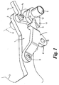
- Figure 1 is a perspective view of the first embodiment;
- Figures 2A and 2B are side elevations of a second embodiment of pedal installed in a motor vehicle in pre and post crash situations; and
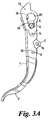
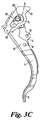
- Figures 3A, 3B and 3C detail the pedal of Figures 2A and 2B in normal operation condition, part de-latched during a crash situation, and fully de-latched after a crash situation.
- In all drawings, like reference numerals are used for like components, and the pedal is referred to as a brake pedal.
- In Figure 1, a brake blade is of two part construction viz a first blade part 1, and a
second blade part 2 located to one lateral side of the blade part 1. The first blade part 1 is provided at one end 3 with a foot pad (not shown) and at the other end 4 is provided with a circular hole by means of which it is fitted onto atubular brake hub 5 for rotation aboutaxis 6. - The
second blade part 2 is constructed from two components, being afirst component 7 secured at one end by arivet 8 to the first blade part 1, and provided at its other end with atongue 9 to engage agroove 10 of second component 11 which is also provided with acircular hole 12 for rotational mounting on thehub 5. - The
first component 7 is cranked away from the first blade part 1 to provide a gap for location of arelease lever 13 secured by arivet 14 to the first blade part 1. Thefirst component 7 is also provided with acircular hole 15 for pivotal connection to one end of a push rod (not shown) eg of a conventional brake booster. - During normal operation, the interaction of release lever 13,
first component 7 and second component 11 maintains pedal position and loading. - During a frontal crash situation of sufficient magnitude, the
release lever 13 is rotated about rivet 14 clear of the second component 11, allowing thefirst component 7 to rotate aboutrivet 8 and to disengagetongue 9 fromgroove 10 from 2 as it rotates aroundhub 5, allowing the pedal to fall away from the driver. - In the embodiment of Figures 2A, 2B, 3A, 3B and 3C, the first blade part 1 is of "U" section having spaced-apart
side cheeks 16 between which is housed thesecond blade part 2 in the normal operation position, as illustrated in Figures 2A and 3A, whilstrelease lever 13 is secured to the first blade part 1 by therivet 14 and , in the normal operation condition serves to latch together the first andsecond blade parts 1 and 2. The first blade part 1 is provided at one end with afoot pad 17, and intermediate its ends is attached to thesecond blade part 2 by therivet 8. Therelease lever 13 is provided with aslot 18 having a narrow throat portion 19 (which engages thehub 5 in the normal, stable, braking position) extending into an enlargedportion 20 in which thehub 5 is located in the unstable, de-latched position of Figure 2B and Figure 3C. - As shown in Figures 2A and 2B,
hole 15 provides for a pivotal connection to apush rod 21 of abrake booster 22 located within engine/transmission compartment 23, the engine/transmission package being indicated at 24 in Figure 2B, and thecompartment 23 being designed to deform in a frontal crash situation of sufficient magnitude. Also illustrated in Figures 2A and 2B is a conventionally providedcross-beam 25 that is designed for minimal deformation in a frontal crash situation of sufficient magnitude. - Comparing the positions of the various components of Figures 2A and 2B, it will be seen that, in a frontal crash situation of sufficient magnitude, the
compartment 23 deforms, and is displaced, rearwardly towards thecross-beam 25. Eventually, and as illustrated in Figure 2A, thelever 13 strikes thecross-beam 25, and is rotated clockwise about itsrivet 14, untilhub 5 enters the enlargedslot portion 20 and the first blade part 1 becomes de-latched from thesecond blade part 2 by rotating in an anti-clockwise direction.
Claims (8)
- A motor vehicle brake or clutch pedal comprising a two part blade, being a first blade part (1) adapted at one end (3) to carry a foot pad, and a second blade part (2) attached to said first blade part (1) and adapted to be connected to a push rod (21) of an operating mechanism of either a brake booster (22) or a clutch, with means (13) to disconnect, or to render ineffective, an interconnection between said second blade part (2) and the first blade part (1) in a frontal crash situation of sufficient magnitude, characterised in that said means (13) is a release lever (13) that is pivotally attached to one of the blade parts (1, 2) and adapted, in a frontal crash situation of sufficient magnitude, to abut a portion (25) of the vehicle designed for minimal deformation, and thereby be rotated to a release position.
- A pedal as claimed in Claim 1, characterised in that said first and second blade parts (1, 2) are mounted for rotation about a common pivot axis (6).
- A pedal as claimed in Claim 1 or Claim 2, characterised in that said first blade part (1) is latched to said second blade part (2) for normal operation, being unlatched upon rotation of said release lever (13) to said release position.
- A pedal as claimed in any one of claims 1 to 3, characterised in that said second blade part (2) is constructed from two components consisting of a first component (7) that is pivotably attachable to a push rod (21) of an operating mechanism of a conventionally-provided brake booster (22) or of a clutch mechanism, that is pivotably attached, at one end, to said first blade part (1), and that at its other end forms an engageable and disengageable connection (9, 10) with one end of a second component (11) which at its other end is mountable for rotation about a pivot axis (6).
- A pedal as claimed in Claim 4, characterised in that said release lever (13) is pivotably attached to said one blade part (1 or 2) in such a position that, in normal operation, rotation of said second component (11) of said other blade part (2 or 1) is precluded by said release lever (13), thereby preventing disengagement of said connection (9, 10), but in a frontal crash situation of sufficient magnitude, is rotated to a position that permits rotation of said second component (11), thereby disengaging said connection (9, 10), thereby freeing said pedal.
- A pedal as claimed in Claim 1, characterised in that said first blade part (1) is of "U" section having spaced-apart side cheeks (16) between which is housed said second blade part (2), the two blade parts (1, 2) being attached to one another by a pin or rivet (8).
- A pedal as claimed in Claim 6, characterised in that said release lever (13) comprises a slot (18) having a narrow throat portion (19) extending to an enlarged portion (20).
- A motor vehicle incorporating at least one pedal as defined in any preceding claim.
Applications Claiming Priority (2)
| Application Number | Priority Date | Filing Date | Title |
|---|---|---|---|
| GB0118227 | 2001-07-26 | ||
| GBGB0118227.8A GB0118227D0 (en) | 2001-07-26 | 2001-07-26 | Motor vehicle brake or clutch pedal |
Publications (3)
| Publication Number | Publication Date |
|---|---|
| EP1279563A2 EP1279563A2 (en) | 2003-01-29 |
| EP1279563A3 EP1279563A3 (en) | 2004-08-25 |
| EP1279563B1 true EP1279563B1 (en) | 2006-04-12 |
Family
ID=9919230
Family Applications (1)
| Application Number | Title | Priority Date | Filing Date |
|---|---|---|---|
| EP02077847A Expired - Lifetime EP1279563B1 (en) | 2001-07-26 | 2002-07-15 | Motor vehicle brake or clutch pedal |
Country Status (7)
| Country | Link |
|---|---|
| US (1) | US6889575B2 (en) |
| EP (1) | EP1279563B1 (en) |
| JP (1) | JP2003112616A (en) |
| AT (1) | ATE323009T1 (en) |
| CA (1) | CA2394509C (en) |
| DE (1) | DE60210543T2 (en) |
| GB (1) | GB0118227D0 (en) |
Families Citing this family (21)
| Publication number | Priority date | Publication date | Assignee | Title |
|---|---|---|---|---|
| GB2391203A (en) * | 2002-07-26 | 2004-02-04 | Ford Global Tech Inc | Pedal lever assembly for a motor vehicle |
| FR2855278B1 (en) * | 2003-05-19 | 2006-09-08 | Peugeot Citroen Automobiles Sa | RETRACTABLE PEDAL DEVICE IN THE EVENT OF A FRONTAL SHOCK ON A VEHICLE |
| KR100534961B1 (en) * | 2003-10-13 | 2005-12-08 | 현대자동차주식회사 | Brake pedal for preventing injury of driver in collision |
| US7415909B2 (en) * | 2004-03-31 | 2008-08-26 | Mazda Motor Corporation | Support structure for pedal of vehicle |
| ES2244328B1 (en) * | 2004-04-16 | 2007-02-16 | Flexngate Automotive Iberica, S.A. | SYSTEM TO DEVOCATE A GOVERNMENT PEDAL FROM A DEVICE OF THE OWN DEVICE TO WHICH IT IS LINKED. |
| FR2885574B1 (en) * | 2005-05-12 | 2007-06-22 | Coutier Moulage Gen Ind | MOTOR VEHICLE PEDAL BEATABLE, IN CASE OF FRONTAL SHOCK ON THE VEHICLE, TO RETRACT |
| KR100657586B1 (en) * | 2005-12-29 | 2006-12-14 | 에스엘 주식회사 | Brake pedal rear anti-roll device of vehicle |
| ES2298019B1 (en) | 2006-02-21 | 2009-07-23 | Flexngate Automotive Iberica, S.A. | SYSTEM TO DEVOCATE A GOVERNMENT PEDAL FROM A DEVICE OF THE OWN DEVICE TO WHICH THE PEDAL IS LINKED. |
| US7712570B2 (en) * | 2006-06-08 | 2010-05-11 | Honda Motor Co., Ltd. | Crash safe vehicle brake assembly |
| KR100757504B1 (en) | 2006-07-26 | 2007-09-11 | 현대자동차주식회사 | Pedal Forced Release |
| US20080047386A1 (en) * | 2006-08-07 | 2008-02-28 | Ridgway Jason R | Automotive foot pedal assembly |
| ITTO20070038A1 (en) * | 2007-01-23 | 2008-07-24 | Ergom Automotive S P A | PEDAL GROUP FOR A MOTOR VEHICLE. |
| ES2320515B1 (en) * | 2007-03-30 | 2010-03-01 | Flexngate Automotive Iberica, S.A. | DEVICE FOR DEVOCATING A GOVERNMENT PEDAL OF THE MECHANISM OF A VEHICLE IN CASE OF ACCIDENT. |
| JP4696216B2 (en) * | 2009-06-16 | 2011-06-08 | 三菱自動車工業株式会社 | Pedal device |
| US8508242B2 (en) * | 2010-01-25 | 2013-08-13 | Ksr Technologies Co. | Inductive position sensor |
| US8794102B2 (en) * | 2010-05-11 | 2014-08-05 | Honda Motor Co., Ltd. | Accelerator pedal assembly for vehicle |
| KR101231341B1 (en) | 2010-12-06 | 2013-02-07 | 현대자동차주식회사 | Brake pedal device |
| EP2578454B1 (en) * | 2011-10-06 | 2014-12-10 | Volvo Car Corporation | Safety arrangement for vehicle pedal |
| JP5758789B2 (en) | 2011-12-14 | 2015-08-05 | トヨタ自動車株式会社 | Vehicle front structure |
| US9889826B2 (en) * | 2014-02-19 | 2018-02-13 | Ventra Group Co. | Variable ratio brake pedal |
| CN115366853B (en) * | 2022-10-25 | 2023-02-17 | 江苏常发农业装备股份有限公司 | Braking device |
Family Cites Families (11)
| Publication number | Priority date | Publication date | Assignee | Title |
|---|---|---|---|---|
| US3807253A (en) * | 1973-01-02 | 1974-04-30 | G Belzile | Brake pedal for a driver instruction vehicle |
| EP0877685B1 (en) * | 1996-01-30 | 2002-04-10 | Ab Volvo | Arrangement and method for activation of a safety arrangement in a vehicle |
| US6327930B1 (en) * | 1996-12-11 | 2001-12-11 | Toyota Jidosha Kabushiki Kaisha | Pedal displacement-control structure for a vehicle |
| JP3781864B2 (en) * | 1997-04-21 | 2006-05-31 | 日産自動車株式会社 | Automotive brake pedal equipment |
| JPH1159350A (en) * | 1997-08-27 | 1999-03-02 | Nissan Motor Co Ltd | Automotive brake pedal structure |
| JP3542709B2 (en) * | 1998-01-13 | 2004-07-14 | 株式会社ヨロズ | Automotive brake pedal device |
| DE69931286T2 (en) * | 1998-01-13 | 2006-11-02 | Nissan Motor Co., Ltd., Yokohama | Vehicle brake pedal assembly |
| JP3381659B2 (en) * | 1999-03-30 | 2003-03-04 | 日産自動車株式会社 | Automotive brake pedal device |
| KR20010064605A (en) * | 1999-12-29 | 2001-07-09 | 이계안 | Leg safeguard structure of driver for automobile |
| GB0006365D0 (en) * | 2000-03-17 | 2000-05-03 | Bck Technology Ltd | Vehicle foot pedal retraction device |
| GB2391203A (en) * | 2002-07-26 | 2004-02-04 | Ford Global Tech Inc | Pedal lever assembly for a motor vehicle |
-
2001
- 2001-07-26 GB GBGB0118227.8A patent/GB0118227D0/en not_active Ceased
-
2002
- 2002-07-15 DE DE60210543T patent/DE60210543T2/en not_active Expired - Lifetime
- 2002-07-15 AT AT02077847T patent/ATE323009T1/en not_active IP Right Cessation
- 2002-07-15 EP EP02077847A patent/EP1279563B1/en not_active Expired - Lifetime
- 2002-07-23 CA CA2394509A patent/CA2394509C/en not_active Expired - Fee Related
- 2002-07-25 JP JP2002216469A patent/JP2003112616A/en active Pending
- 2002-07-25 US US10/202,948 patent/US6889575B2/en not_active Expired - Lifetime
Also Published As
| Publication number | Publication date |
|---|---|
| DE60210543T2 (en) | 2007-03-08 |
| ATE323009T1 (en) | 2006-04-15 |
| EP1279563A3 (en) | 2004-08-25 |
| US20030019320A1 (en) | 2003-01-30 |
| JP2003112616A (en) | 2003-04-15 |
| GB0118227D0 (en) | 2001-09-19 |
| CA2394509C (en) | 2010-05-04 |
| US6889575B2 (en) | 2005-05-10 |
| DE60210543D1 (en) | 2006-05-24 |
| CA2394509A1 (en) | 2003-01-26 |
| EP1279563A2 (en) | 2003-01-29 |
Similar Documents
| Publication | Publication Date | Title |
|---|---|---|
| CA2394509C (en) | Motor vehicle brake or clutch pedal | |
| US5996439A (en) | Brake pedal mechanism | |
| EP1260419B1 (en) | A system for releasing a pedal of a motor vehicle in the event of a frontal impact | |
| JPH115517A (en) | Automotive brake pedal device | |
| US5555773A (en) | Parking brake system | |
| EP1110791B1 (en) | Pedal box for vehicle etc. | |
| US6286389B1 (en) | Parking brake actuating assembly with improved lockout structure | |
| JP3804372B2 (en) | Automobile pedal support structure | |
| EP1759944B1 (en) | Parking brake apparatus | |
| JP4006676B2 (en) | Pedal support structure | |
| US6986531B2 (en) | Steering column linkage tilt lever | |
| JP2003506258A (en) | Actuator for parking brake | |
| EP1418102A2 (en) | Parking brake lever | |
| JP5656113B2 (en) | Vehicle pedal device | |
| JP4234033B2 (en) | Automobile operation pedal device | |
| JP2000163147A (en) | Pedal bracket structure | |
| JP2959235B2 (en) | Pedal device | |
| EP1038720A2 (en) | Vehicle pedal box | |
| EP1344691B1 (en) | Arrangement for permitting vehicle foot pedal retraction, and vehicle incorporting same | |
| JP3900235B2 (en) | Vehicle pedal release structure | |
| JPH1159350A (en) | Automotive brake pedal structure | |
| JP2020201825A (en) | Operation pedal unit for vehicles | |
| JP3459347B2 (en) | Automotive brake pedal structure | |
| US8250946B2 (en) | Parking brake for a vehicle | |
| EP1759945B1 (en) | Base frame and parking brake device |
Legal Events
| Date | Code | Title | Description |
|---|---|---|---|
| PUAI | Public reference made under article 153(3) epc to a published international application that has entered the european phase |
Free format text: ORIGINAL CODE: 0009012 |
|
| AK | Designated contracting states |
Designated state(s): AT BE BG CH CY CZ DE DK EE ES FI FR GB GR IE IT LI LU MC NL PT SE SK TR |
|
| AX | Request for extension of the european patent |
Extension state: AL LT LV MK RO SI |
|
| PUAL | Search report despatched |
Free format text: ORIGINAL CODE: 0009013 |
|
| RAP1 | Party data changed (applicant data changed or rights of an application transferred) |
Owner name: KSR AUTOMOTIVE LIMITED |
|
| AK | Designated contracting states |
Kind code of ref document: A3 Designated state(s): AT BE BG CH CY CZ DE DK EE ES FI FR GB GR IE IT LI LU MC NL PT SE SK TR |
|
| AX | Request for extension of the european patent |
Extension state: AL LT LV MK RO SI |
|
| 17P | Request for examination filed |
Effective date: 20050104 |
|
| AKX | Designation fees paid |
Designated state(s): AT BE BG CH CY CZ DE DK EE ES FI FR GB GR IE IT LI LU MC NL PT SE SK TR |
|
| 17Q | First examination report despatched |
Effective date: 20050502 |
|
| GRAP | Despatch of communication of intention to grant a patent |
Free format text: ORIGINAL CODE: EPIDOSNIGR1 |
|
| GRAS | Grant fee paid |
Free format text: ORIGINAL CODE: EPIDOSNIGR3 |
|
| GRAA | (expected) grant |
Free format text: ORIGINAL CODE: 0009210 |
|
| AK | Designated contracting states |
Kind code of ref document: B1 Designated state(s): AT BE BG CH CY CZ DE DK EE ES FI FR GB GR IE IT LI LU MC NL PT SE SK TR |
|
| PG25 | Lapsed in a contracting state [announced via postgrant information from national office to epo] |
Ref country code: IT Free format text: LAPSE BECAUSE OF FAILURE TO SUBMIT A TRANSLATION OF THE DESCRIPTION OR TO PAY THE FEE WITHIN THE PRESCRIBED TIME-LIMIT;WARNING: LAPSES OF ITALIAN PATENTS WITH EFFECTIVE DATE BEFORE 2007 MAY HAVE OCCURRED AT ANY TIME BEFORE 2007. THE CORRECT EFFECTIVE DATE MAY BE DIFFERENT FROM THE ONE RECORDED. Effective date: 20060412 Ref country code: FI Free format text: LAPSE BECAUSE OF FAILURE TO SUBMIT A TRANSLATION OF THE DESCRIPTION OR TO PAY THE FEE WITHIN THE PRESCRIBED TIME-LIMIT Effective date: 20060412 Ref country code: CH Free format text: LAPSE BECAUSE OF FAILURE TO SUBMIT A TRANSLATION OF THE DESCRIPTION OR TO PAY THE FEE WITHIN THE PRESCRIBED TIME-LIMIT Effective date: 20060412 Ref country code: SK Free format text: LAPSE BECAUSE OF FAILURE TO SUBMIT A TRANSLATION OF THE DESCRIPTION OR TO PAY THE FEE WITHIN THE PRESCRIBED TIME-LIMIT Effective date: 20060412 Ref country code: NL Free format text: LAPSE BECAUSE OF FAILURE TO SUBMIT A TRANSLATION OF THE DESCRIPTION OR TO PAY THE FEE WITHIN THE PRESCRIBED TIME-LIMIT Effective date: 20060412 Ref country code: CZ Free format text: LAPSE BECAUSE OF FAILURE TO SUBMIT A TRANSLATION OF THE DESCRIPTION OR TO PAY THE FEE WITHIN THE PRESCRIBED TIME-LIMIT Effective date: 20060412 Ref country code: AT Free format text: LAPSE BECAUSE OF FAILURE TO SUBMIT A TRANSLATION OF THE DESCRIPTION OR TO PAY THE FEE WITHIN THE PRESCRIBED TIME-LIMIT Effective date: 20060412 Ref country code: BE Free format text: LAPSE BECAUSE OF FAILURE TO SUBMIT A TRANSLATION OF THE DESCRIPTION OR TO PAY THE FEE WITHIN THE PRESCRIBED TIME-LIMIT Effective date: 20060412 Ref country code: LI Free format text: LAPSE BECAUSE OF FAILURE TO SUBMIT A TRANSLATION OF THE DESCRIPTION OR TO PAY THE FEE WITHIN THE PRESCRIBED TIME-LIMIT Effective date: 20060412 |
|
| REG | Reference to a national code |
Ref country code: GB Ref legal event code: FG4D |
|
| REG | Reference to a national code |
Ref country code: CH Ref legal event code: EP |
|
| REF | Corresponds to: |
Ref document number: 60210543 Country of ref document: DE Date of ref document: 20060524 Kind code of ref document: P |
|
| REG | Reference to a national code |
Ref country code: IE Ref legal event code: FG4D |
|
| PG25 | Lapsed in a contracting state [announced via postgrant information from national office to epo] |
Ref country code: DK Free format text: LAPSE BECAUSE OF FAILURE TO SUBMIT A TRANSLATION OF THE DESCRIPTION OR TO PAY THE FEE WITHIN THE PRESCRIBED TIME-LIMIT Effective date: 20060712 |
|
| PG25 | Lapsed in a contracting state [announced via postgrant information from national office to epo] |
Ref country code: IE Free format text: LAPSE BECAUSE OF NON-PAYMENT OF DUE FEES Effective date: 20060717 |
|
| PG25 | Lapsed in a contracting state [announced via postgrant information from national office to epo] |
Ref country code: ES Free format text: LAPSE BECAUSE OF FAILURE TO SUBMIT A TRANSLATION OF THE DESCRIPTION OR TO PAY THE FEE WITHIN THE PRESCRIBED TIME-LIMIT Effective date: 20060723 |
|
| PG25 | Lapsed in a contracting state [announced via postgrant information from national office to epo] |
Ref country code: MC Free format text: LAPSE BECAUSE OF NON-PAYMENT OF DUE FEES Effective date: 20060731 |
|
| REG | Reference to a national code |
Ref country code: SE Ref legal event code: TRGR |
|
| PG25 | Lapsed in a contracting state [announced via postgrant information from national office to epo] |
Ref country code: PT Free format text: LAPSE BECAUSE OF FAILURE TO SUBMIT A TRANSLATION OF THE DESCRIPTION OR TO PAY THE FEE WITHIN THE PRESCRIBED TIME-LIMIT Effective date: 20060912 |
|
| NLV1 | Nl: lapsed or annulled due to failure to fulfill the requirements of art. 29p and 29m of the patents act | ||
| REG | Reference to a national code |
Ref country code: CH Ref legal event code: PL |
|
| PLBE | No opposition filed within time limit |
Free format text: ORIGINAL CODE: 0009261 |
|
| STAA | Information on the status of an ep patent application or granted ep patent |
Free format text: STATUS: NO OPPOSITION FILED WITHIN TIME LIMIT |
|
| 26N | No opposition filed |
Effective date: 20070115 |
|
| EN | Fr: translation not filed | ||
| PG25 | Lapsed in a contracting state [announced via postgrant information from national office to epo] |
Ref country code: GR Free format text: LAPSE BECAUSE OF FAILURE TO SUBMIT A TRANSLATION OF THE DESCRIPTION OR TO PAY THE FEE WITHIN THE PRESCRIBED TIME-LIMIT Effective date: 20060713 Ref country code: FR Free format text: LAPSE BECAUSE OF FAILURE TO SUBMIT A TRANSLATION OF THE DESCRIPTION OR TO PAY THE FEE WITHIN THE PRESCRIBED TIME-LIMIT Effective date: 20070309 |
|
| PG25 | Lapsed in a contracting state [announced via postgrant information from national office to epo] |
Ref country code: EE Free format text: LAPSE BECAUSE OF FAILURE TO SUBMIT A TRANSLATION OF THE DESCRIPTION OR TO PAY THE FEE WITHIN THE PRESCRIBED TIME-LIMIT Effective date: 20060412 Ref country code: BG Free format text: LAPSE BECAUSE OF FAILURE TO SUBMIT A TRANSLATION OF THE DESCRIPTION OR TO PAY THE FEE WITHIN THE PRESCRIBED TIME-LIMIT Effective date: 20060712 |
|
| PG25 | Lapsed in a contracting state [announced via postgrant information from national office to epo] |
Ref country code: LU Free format text: LAPSE BECAUSE OF NON-PAYMENT OF DUE FEES Effective date: 20060715 Ref country code: TR Free format text: LAPSE BECAUSE OF FAILURE TO SUBMIT A TRANSLATION OF THE DESCRIPTION OR TO PAY THE FEE WITHIN THE PRESCRIBED TIME-LIMIT Effective date: 20060412 |
|
| PG25 | Lapsed in a contracting state [announced via postgrant information from national office to epo] |
Ref country code: FR Free format text: LAPSE BECAUSE OF FAILURE TO SUBMIT A TRANSLATION OF THE DESCRIPTION OR TO PAY THE FEE WITHIN THE PRESCRIBED TIME-LIMIT Effective date: 20060412 Ref country code: CY Free format text: LAPSE BECAUSE OF FAILURE TO SUBMIT A TRANSLATION OF THE DESCRIPTION OR TO PAY THE FEE WITHIN THE PRESCRIBED TIME-LIMIT Effective date: 20060412 |
|
| PGFP | Annual fee paid to national office [announced via postgrant information from national office to epo] |
Ref country code: SE Payment date: 20110712 Year of fee payment: 10 |
|
| REG | Reference to a national code |
Ref country code: SE Ref legal event code: EUG |
|
| PG25 | Lapsed in a contracting state [announced via postgrant information from national office to epo] |
Ref country code: SE Free format text: LAPSE BECAUSE OF NON-PAYMENT OF DUE FEES Effective date: 20120716 |
|
| PGFP | Annual fee paid to national office [announced via postgrant information from national office to epo] |
Ref country code: GB Payment date: 20130710 Year of fee payment: 12 |
|
| REG | Reference to a national code |
Ref country code: DE Ref legal event code: R082 Ref document number: 60210543 Country of ref document: DE Representative=s name: GESTHUYSEN PATENT- UND RECHTSANWAELTE, DE |
|
| REG | Reference to a national code |
Ref country code: GB Ref legal event code: 732E Free format text: REGISTERED BETWEEN 20140821 AND 20140827 |
|
| REG | Reference to a national code |
Ref country code: DE Ref legal event code: R081 Ref document number: 60210543 Country of ref document: DE Owner name: KSR IP HOLDINGS LLC, WILMINGTON, US Free format text: FORMER OWNER: KSR AUTOMOTIVE LTD., SCUNTHORPE, GB Effective date: 20140902 Ref country code: DE Ref legal event code: R082 Ref document number: 60210543 Country of ref document: DE Representative=s name: GESTHUYSEN PATENT- UND RECHTSANWAELTE, DE Effective date: 20140902 |
|
| GBPC | Gb: european patent ceased through non-payment of renewal fee |
Effective date: 20140715 |
|
| PG25 | Lapsed in a contracting state [announced via postgrant information from national office to epo] |
Ref country code: GB Free format text: LAPSE BECAUSE OF NON-PAYMENT OF DUE FEES Effective date: 20140715 |
|
| PGFP | Annual fee paid to national office [announced via postgrant information from national office to epo] |
Ref country code: DE Payment date: 20190702 Year of fee payment: 18 |
|
| REG | Reference to a national code |
Ref country code: DE Ref legal event code: R119 Ref document number: 60210543 Country of ref document: DE |
|
| PG25 | Lapsed in a contracting state [announced via postgrant information from national office to epo] |
Ref country code: DE Free format text: LAPSE BECAUSE OF NON-PAYMENT OF DUE FEES Effective date: 20210202 |