EP1279524A2 - Castor wheel construction - Google Patents
Castor wheel construction Download PDFInfo
- Publication number
- EP1279524A2 EP1279524A2 EP02016190A EP02016190A EP1279524A2 EP 1279524 A2 EP1279524 A2 EP 1279524A2 EP 02016190 A EP02016190 A EP 02016190A EP 02016190 A EP02016190 A EP 02016190A EP 1279524 A2 EP1279524 A2 EP 1279524A2
- Authority
- EP
- European Patent Office
- Prior art keywords
- wheel body
- wheel
- castor
- construction
- lever
- Prior art date
- Legal status (The legal status is an assumption and is not a legal conclusion. Google has not performed a legal analysis and makes no representation as to the accuracy of the status listed.)
- Granted
Links
Images

Classifications
-
- B—PERFORMING OPERATIONS; TRANSPORTING
- B60—VEHICLES IN GENERAL
- B60B—VEHICLE WHEELS; CASTORS; AXLES FOR WHEELS OR CASTORS; INCREASING WHEEL ADHESION
- B60B33/00—Castors in general ; Anti-clogging castors
- B60B33/0002—Castors in general ; Anti-clogging castors assembling to the object, e.g. furniture
- B60B33/0015—Castors in general ; Anti-clogging castors assembling to the object, e.g. furniture characterised by adaptations made to castor
- B60B33/0021—Castors in general ; Anti-clogging castors assembling to the object, e.g. furniture characterised by adaptations made to castor in the form of a mounting pin
-
- B—PERFORMING OPERATIONS; TRANSPORTING
- B60—VEHICLES IN GENERAL
- B60B—VEHICLE WHEELS; CASTORS; AXLES FOR WHEELS OR CASTORS; INCREASING WHEEL ADHESION
- B60B33/00—Castors in general ; Anti-clogging castors
- B60B33/0028—Construction of wheels; methods of assembling on axle
-
- B—PERFORMING OPERATIONS; TRANSPORTING
- B60—VEHICLES IN GENERAL
- B60B—VEHICLE WHEELS; CASTORS; AXLES FOR WHEELS OR CASTORS; INCREASING WHEEL ADHESION
- B60B33/00—Castors in general ; Anti-clogging castors
- B60B33/0036—Castors in general ; Anti-clogging castors characterised by type of wheels
- B60B33/0042—Double or twin wheels
-
- B—PERFORMING OPERATIONS; TRANSPORTING
- B60—VEHICLES IN GENERAL
- B60B—VEHICLE WHEELS; CASTORS; AXLES FOR WHEELS OR CASTORS; INCREASING WHEEL ADHESION
- B60B33/00—Castors in general ; Anti-clogging castors
- B60B33/0047—Castors in general ; Anti-clogging castors characterised by details of the rolling axle
- B60B33/0049—Castors in general ; Anti-clogging castors characterised by details of the rolling axle the rolling axle being horizontal
-
- B—PERFORMING OPERATIONS; TRANSPORTING
- B60—VEHICLES IN GENERAL
- B60B—VEHICLE WHEELS; CASTORS; AXLES FOR WHEELS OR CASTORS; INCREASING WHEEL ADHESION
- B60B33/00—Castors in general ; Anti-clogging castors
- B60B33/0047—Castors in general ; Anti-clogging castors characterised by details of the rolling axle
- B60B33/0057—Castors in general ; Anti-clogging castors characterised by details of the rolling axle the rolling axle being offset from swivel axis
-
- B—PERFORMING OPERATIONS; TRANSPORTING
- B60—VEHICLES IN GENERAL
- B60B—VEHICLE WHEELS; CASTORS; AXLES FOR WHEELS OR CASTORS; INCREASING WHEEL ADHESION
- B60B33/00—Castors in general ; Anti-clogging castors
- B60B33/006—Castors in general ; Anti-clogging castors characterised by details of the swivel mechanism
- B60B33/0065—Castors in general ; Anti-clogging castors characterised by details of the swivel mechanism characterised by details of the swivel axis
- B60B33/0068—Castors in general ; Anti-clogging castors characterised by details of the swivel mechanism characterised by details of the swivel axis the swivel axis being vertical
-
- B—PERFORMING OPERATIONS; TRANSPORTING
- B60—VEHICLES IN GENERAL
- B60B—VEHICLE WHEELS; CASTORS; AXLES FOR WHEELS OR CASTORS; INCREASING WHEEL ADHESION
- B60B33/00—Castors in general ; Anti-clogging castors
- B60B33/006—Castors in general ; Anti-clogging castors characterised by details of the swivel mechanism
- B60B33/0065—Castors in general ; Anti-clogging castors characterised by details of the swivel mechanism characterised by details of the swivel axis
- B60B33/0073—Castors in general ; Anti-clogging castors characterised by details of the swivel mechanism characterised by details of the swivel axis the swivel axis being symmetrical to wheel or wheels
-
- B—PERFORMING OPERATIONS; TRANSPORTING
- B60—VEHICLES IN GENERAL
- B60B—VEHICLE WHEELS; CASTORS; AXLES FOR WHEELS OR CASTORS; INCREASING WHEEL ADHESION
- B60B33/00—Castors in general ; Anti-clogging castors
- B60B33/0078—Castors in general ; Anti-clogging castors characterised by details of the wheel braking mechanism
- B60B33/0086—Castors in general ; Anti-clogging castors characterised by details of the wheel braking mechanism acting on rim or side portion of tyre
-
- B—PERFORMING OPERATIONS; TRANSPORTING
- B60—VEHICLES IN GENERAL
- B60B—VEHICLE WHEELS; CASTORS; AXLES FOR WHEELS OR CASTORS; INCREASING WHEEL ADHESION
- B60B33/00—Castors in general ; Anti-clogging castors
- B60B33/02—Castors in general ; Anti-clogging castors with disengageable swivel action, i.e. comprising a swivel locking mechanism
- B60B33/021—Castors in general ; Anti-clogging castors with disengageable swivel action, i.e. comprising a swivel locking mechanism combined with braking of castor wheel
Definitions
- the present invention relates to a castor wheel construction.
- Castor wheels including a locking and unlocking device for respectively locking and unlocking the rotary movement of the wheel, which device conventionally comprise a pedal lever operating on the wheel by different types of interference or friction means are already known.
- the braked castor wheels are used in a broad range of applications, and these castor wheels must be reliable in operation, and economically advantageous from a mere construction standpoint.
- the aim of the present invention is to provide such a castor wheel construction having very good operating and safety characteristics, while being very simple construction-wise.
- a main object of the invention is to provide such a castor wheel construction which comprises a very small number of component parts, which can be easily made and easily assembled.
- Yet another object of the present invention is to provide such a castor wheel construction the use of which is easy and self-evident.
- a castor wheel construction comprising a supporting hub supporting a wheel body and a pedal lever, and engaging means, driven by said pedal lever, said engaging means defining at least a locking position for locking a rotation of a wheel body and at least a free position for allowing said wheel body to freely rotate, characterized in that said engaging means comprise at least a tooth rigid with said pedal lever and designed for engaging a plurality of ridges which are circumferentially arranged on at least a surface of said wheel body.
- the castor wheel construction according to the present invention which has been generally indicated by the reference number 1, comprises a hub 2, including an end-piece 3 for connection with an article, not specifically shown, which must be provided with castor wheels.
- the hub 2 supports a wheel body, comprising two half-portions 4 and 5, which are made rigid with one another on said hub 2, in order to allow the wheel body to rotate with respect to the hub.
- the two half-portions 4 and 5 of the wheel body have each an inner surface, respectively indicated at 6 and 7, facing the hub 2 and including bosses or ridges 8, arranged along a circumference about the rotary axis of the wheel body.
- the ridges 8 are suitably beveled and have in the shown embodiment a drop shape, with a longitudinal axis radially extending with respect to the rotary axis of the wheel body.
- the two pluralities of ridges 8, each for each half-portion 4 and 5 of the wheel body, are respectively designed for engaging a pair of teeth 9, with a tooth for each side, of a fork lever 10, pivoted at a pivot pin 11 on the hub 2.
- the fork lever 10 is moreover provided with a pedal 12, projecting outward of the wheel body to be driven by a foot, thereby displacing the fork lever 10 from a wheel body free rotary position, shown in figure 3, to a wheel body locked position, as shown in figure 2.
- the drop-like beveled configuration of the ridges, and a rounded end of the tooth allow to obtain a fluidic engagement between the tooth and ridges to prevent any jams for occurring as the tooth end is precisely arranged at a tooth, as the castor wheel must be locked.
- the hub 2 comprises an interference element 13, including, for example, a boss or the like, designed for interfering with the lever 10, thereby requiring a given effort in order to disengage said lever from the interference element.
- interference element 10 and limit element 14 are made as a single body with the respective components they are rigid with, as said components are made.
- the invention provides a castor wheel construction which is very simple and unexpensive from a mere construction standpoint, while having very good operating features.
- the used materials and the contingent size and shapes can be any, depending on requirements and the status of the art.
Landscapes
- Engineering & Computer Science (AREA)
- Mechanical Engineering (AREA)
- Mechanical Control Devices (AREA)
- Arrangement Or Mounting Of Propulsion Units For Vehicles (AREA)
- Body Structure For Vehicles (AREA)
- Vehicle Body Suspensions (AREA)
- Acyclic And Carbocyclic Compounds In Medicinal Compositions (AREA)
- Snaps, Bayonet Connections, Set Pins, And Snap Rings (AREA)
- Handcart (AREA)
Abstract
Description
- The present invention relates to a castor wheel construction.
- Castor wheels including a locking and unlocking device for respectively locking and unlocking the rotary movement of the wheel, which device conventionally comprise a pedal lever operating on the wheel by different types of interference or friction means are already known.
- The braked castor wheels are used in a broad range of applications, and these castor wheels must be reliable in operation, and economically advantageous from a mere construction standpoint.
- Accordingly, the aim of the present invention is to provide such a castor wheel construction having very good operating and safety characteristics, while being very simple construction-wise.
- Within the scope of the above mentioned aim, a main object of the invention is to provide such a castor wheel construction which comprises a very small number of component parts, which can be easily made and easily assembled.
- Yet another object of the present invention is to provide such a castor wheel construction the use of which is easy and self-evident.
- According to one aspect of the present invention, the above mentioned aim and objects, as well as yet other objects, which will become more apparent hereinafter, are achieved by a castor wheel construction comprising a supporting hub supporting a wheel body and a pedal lever, and engaging means, driven by said pedal lever, said engaging means defining at least a locking position for locking a rotation of a wheel body and at least a free position for allowing said wheel body to freely rotate, characterized in that said engaging means comprise at least a tooth rigid with said pedal lever and designed for engaging a plurality of ridges which are circumferentially arranged on at least a surface of said wheel body.
- Further characteristics and advantages of the present invention will become more apparent hereinafter from the following detailed disclosure of a preferred, though not exclusive, embodiment of the invention, which is illustrated, by way of an indicative, but not limitative, example in the accompanying drawings, where:
- Figure 1 is a front cross-sectional elevation view of the castor wheel construction according to the invention;
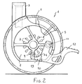
- Figure 2 is a further side elevation view, partially broken away, of the castor wheel construction according to the present invention, being shown in a locked position thereof;
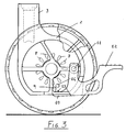
and - Figure 3 is a view similar to figure 2, but showing the castor wheel construction according to the present invention, in a free rotary position or condition thereof.
- With reference to the number references of the above mentioned figures, the castor wheel construction according to the present invention, which has been generally indicated by the
reference number 1, comprises ahub 2, including an end-piece 3 for connection with an article, not specifically shown, which must be provided with castor wheels. - The
hub 2 supports a wheel body, comprising two half-portions hub 2, in order to allow the wheel body to rotate with respect to the hub. - The two half-
portions hub 2 and including bosses orridges 8, arranged along a circumference about the rotary axis of the wheel body. - The
ridges 8 are suitably beveled and have in the shown embodiment a drop shape, with a longitudinal axis radially extending with respect to the rotary axis of the wheel body. - The two pluralities of
ridges 8, each for each half-portion teeth 9, with a tooth for each side, of afork lever 10, pivoted at apivot pin 11 on thehub 2. - The
fork lever 10 is moreover provided with apedal 12, projecting outward of the wheel body to be driven by a foot, thereby displacing thefork lever 10 from a wheel body free rotary position, shown in figure 3, to a wheel body locked position, as shown in figure 2. - The drop-like beveled configuration of the ridges, and a rounded end of the tooth, allow to obtain a fluidic engagement between the tooth and ridges to prevent any jams for occurring as the tooth end is precisely arranged at a tooth, as the castor wheel must be locked.
- In order to prevent the
fork lever 10 from accidentally moving away from the locking position, thehub 2 comprises aninterference element 13, including, for example, a boss or the like, designed for interfering with thelever 10, thereby requiring a given effort in order to disengage said lever from the interference element. - Moreover, an end of stroke or
limit element 14, limiting the rotary movement of thelever 10 in the wheel locking position is provided. - All the disclosed elements, such as the
ridges 8,interference element 10 andlimit element 14 are made as a single body with the respective components they are rigid with, as said components are made. - It has been found that the invention fully achieves the intended aim and objects.
- In fact, the invention provides a castor wheel construction which is very simple and unexpensive from a mere construction standpoint, while having very good operating features.
- By a very small number of components, all of which can be easily made and assembled, a castor wheel construction with very good operating safety features has been provided.
- In practicing the invention, the used materials and the contingent size and shapes, can be any, depending on requirements and the status of the art.
Claims (7)
- A castor wheel construction comprising a supporting hub supporting a wheel body and a pedal lever, and engaging means, driven by said pedal lever, said engaging means defining at least a locking position for locking a rotation of a wheel body and at least a free position for allowing said wheel body to freely rotate, characterized in that said engaging means comprise at least a tooth rigid with said pedal lever and designed for engaging a plurality of ridges which are circumferentially arranged on at least a surface of said wheel body.
- A castor wheel construction, according to Claim 1, characterized in that said wheel body comprises two half-portions made rigid with one another on said hub to allow said wheel body to rotate, with respect to said hub, and that the two half-portions of the wheel body have each an inner surface facing said hub and including ridges arranged along a circumference about the rotary axis of the wheel body.
- A castor wheel construction, according to Claim 2, characterized in that said ridges are beveled and have a drop shape, with a longitudinal axis radially arranged with respect to the rotary axis of the wheel body.
- A castor wheel construction, according to Claim 1, characterized in that said two pluralities of ridges, each for each half-portion of the wheel body, are respectively designed for engaging a pair of teeth, i.e. a tooth for each side of said lever, which has a fork-shape and is pivoted on a pin on said hub.
- A castor wheel construction, according to Claim 1, characterized in that said wheel construction further comprises an interference element designed for engaging said lever at said wheel body rotary locking position, thereby an effort would be required for disengaging said lever from said interference element and hence from said locked position of said wheel body.
- A castor wheel construction, according to Claim 1, characterized in that said castor wheel construction comprises a limit element designed for limiting the rotary movement of said lever in the castor wheel locking position.
- A castor wheel construction, according to Claim 1, characterized in that all the elements of said castor wheel construction such as said ridges, interference element and limit element are made as a single body, with their respective components to which they are coupled during the making process of said components.
Applications Claiming Priority (2)
| Application Number | Priority Date | Filing Date | Title |
|---|---|---|---|
| IT2001MI000421U ITMI20010421U1 (en) | 2001-07-24 | 2001-07-24 | STRUCTURE OF SWIVEL WHEEL |
| ITMI20010421U | 2001-07-24 |
Publications (3)
| Publication Number | Publication Date |
|---|---|
| EP1279524A2 true EP1279524A2 (en) | 2003-01-29 |
| EP1279524A3 EP1279524A3 (en) | 2004-03-17 |
| EP1279524B1 EP1279524B1 (en) | 2006-05-03 |
Family
ID=11447073
Family Applications (1)
| Application Number | Title | Priority Date | Filing Date |
|---|---|---|---|
| EP02016190A Expired - Lifetime EP1279524B1 (en) | 2001-07-24 | 2002-07-22 | Castor wheel construction |
Country Status (6)
| Country | Link |
|---|---|
| US (1) | US20030019075A1 (en) |
| EP (1) | EP1279524B1 (en) |
| AT (1) | ATE324998T1 (en) |
| DE (1) | DE60211073T2 (en) |
| ES (1) | ES2259687T3 (en) |
| IT (1) | ITMI20010421U1 (en) |
Families Citing this family (5)
| Publication number | Priority date | Publication date | Assignee | Title |
|---|---|---|---|---|
| US8196237B2 (en) * | 2008-05-23 | 2012-06-12 | Stryker Corporation | Patient support brake system |
| FR2956613B1 (en) * | 2010-02-19 | 2012-02-17 | Tente Roulettes Polymeres Bruandet | ROULETTE FOR FURNITURE OR THE LIKE WITH MEANS OF BLOCKING |
| US8789662B2 (en) | 2011-11-09 | 2014-07-29 | Stryker Corporation | Wheeled carriage with brake lock system |
| US9533530B2 (en) * | 2013-12-11 | 2017-01-03 | Wonderland Nurserygoods Company Limited | Wheel assembly for an infant support apparatus |
| USD986695S1 (en) * | 2022-06-09 | 2023-05-23 | Keying Lei | Caster wheel |
Family Cites Families (5)
| Publication number | Priority date | Publication date | Assignee | Title |
|---|---|---|---|---|
| GB839272A (en) * | 1958-05-02 | 1960-06-29 | Flexello Castors & Wheels Ltd | Improvements in castors |
| US4333207A (en) * | 1980-12-22 | 1982-06-08 | Shepherd Products U.S. Inc. | Twin wheel caster brake |
| GB8620924D0 (en) * | 1986-08-29 | 1986-10-08 | Flexello Castors & Wheels | Castor |
| IT1264730B1 (en) * | 1993-11-03 | 1996-10-04 | Emilsider Meccanica | BRAKING DEVICE FOR A SELF-ADJUSTABLE TWIN WHEEL |
| JP3283822B2 (en) * | 1998-05-08 | 2002-05-20 | 賢親 鈴木 | Casters with brake device |
-
2001
- 2001-07-24 IT IT2001MI000421U patent/ITMI20010421U1/en unknown
-
2002
- 2002-07-22 ES ES02016190T patent/ES2259687T3/en not_active Expired - Lifetime
- 2002-07-22 AT AT02016190T patent/ATE324998T1/en not_active IP Right Cessation
- 2002-07-22 EP EP02016190A patent/EP1279524B1/en not_active Expired - Lifetime
- 2002-07-22 DE DE60211073T patent/DE60211073T2/en not_active Expired - Lifetime
- 2002-07-23 US US10/200,946 patent/US20030019075A1/en not_active Abandoned
Non-Patent Citations (1)
| Title |
|---|
| None |
Also Published As
| Publication number | Publication date |
|---|---|
| ATE324998T1 (en) | 2006-06-15 |
| DE60211073T2 (en) | 2006-12-07 |
| ITMI20010421U1 (en) | 2003-01-24 |
| ES2259687T3 (en) | 2006-10-16 |
| ITMI20010421V0 (en) | 2001-07-24 |
| EP1279524A3 (en) | 2004-03-17 |
| US20030019075A1 (en) | 2003-01-30 |
| EP1279524B1 (en) | 2006-05-03 |
| DE60211073D1 (en) | 2006-06-08 |
Similar Documents
| Publication | Publication Date | Title |
|---|---|---|
| EP2669144B1 (en) | Brake device and child carrier provided with the same | |
| US7810613B2 (en) | Cart braking device | |
| EP2883780B1 (en) | Wheel assembly for an infant support apparatus | |
| CN105216547A (en) | With the castor of drg | |
| US6219881B1 (en) | Brake for caster | |
| EP1055528A1 (en) | Brake device with brake adjustment system | |
| EP1591340A2 (en) | Brake assembly for a stroller | |
| US7254971B2 (en) | Combination lock | |
| EP1279524A2 (en) | Castor wheel construction | |
| US20110010892A1 (en) | Castor with brake device | |
| WO2007085570A1 (en) | Friction braking device | |
| US6499197B1 (en) | Buckle device with improved safety | |
| US20240083484A1 (en) | Brake device for wheel set of baby carriage | |
| JP4331466B2 (en) | Cable stripping tool | |
| KR102373645B1 (en) | caster with brake | |
| EP3658097B1 (en) | Brake | |
| EP2409857B1 (en) | A wheel construction including a locking device | |
| IT201600105859A1 (en) | Implementation assembly of a parking brake | |
| KR101648833B1 (en) | Hand brake device | |
| CN218806034U (en) | Brake assembly and cart comprising same | |
| EP1270365A1 (en) | Child pushchair | |
| CN209870360U (en) | Handle structure of parking brake system | |
| EP3805138B1 (en) | Detachable centrifugal brake for lift equipment | |
| CN115303351B (en) | Braking device | |
| CN209320593U (en) | A kind of medical caster structure with brake function |
Legal Events
| Date | Code | Title | Description |
|---|---|---|---|
| PUAI | Public reference made under article 153(3) epc to a published international application that has entered the european phase |
Free format text: ORIGINAL CODE: 0009012 |
|
| AK | Designated contracting states |
Designated state(s): AT BE BG CH CY CZ DE DK EE ES FI FR GB GR IE IT LI LU MC NL PT SE SK TR |
|
| AX | Request for extension of the european patent |
Extension state: AL LT LV MK RO SI |
|
| PUAL | Search report despatched |
Free format text: ORIGINAL CODE: 0009013 |
|
| AK | Designated contracting states |
Kind code of ref document: A3 Designated state(s): AT BE BG CH CY CZ DE DK EE ES FI FR GB GR IE IT LI LU MC NL PT SE SK TR |
|
| AX | Request for extension of the european patent |
Extension state: AL LT LV MK RO SI |
|
| 17P | Request for examination filed |
Effective date: 20040506 |
|
| AKX | Designation fees paid |
Designated state(s): AT BE BG CH CY CZ DE DK EE ES FI FR GB GR IE IT LI LU MC NL PT SE SK TR |
|
| 17Q | First examination report despatched |
Effective date: 20041206 |
|
| GRAP | Despatch of communication of intention to grant a patent |
Free format text: ORIGINAL CODE: EPIDOSNIGR1 |
|
| GRAS | Grant fee paid |
Free format text: ORIGINAL CODE: EPIDOSNIGR3 |
|
| RAP1 | Party data changed (applicant data changed or rights of an application transferred) |
Owner name: O.G.T.M. OFFICINE MECCANICHE S.R.L. |
|
| GRAA | (expected) grant |
Free format text: ORIGINAL CODE: 0009210 |
|
| AK | Designated contracting states |
Kind code of ref document: B1 Designated state(s): AT BE BG CH CY CZ DE DK EE ES FI FR GB GR IE IT LI LU MC NL PT SE SK TR |
|
| PG25 | Lapsed in a contracting state [announced via postgrant information from national office to epo] |
Ref country code: CZ Free format text: LAPSE BECAUSE OF FAILURE TO SUBMIT A TRANSLATION OF THE DESCRIPTION OR TO PAY THE FEE WITHIN THE PRESCRIBED TIME-LIMIT Effective date: 20060503 Ref country code: AT Free format text: LAPSE BECAUSE OF FAILURE TO SUBMIT A TRANSLATION OF THE DESCRIPTION OR TO PAY THE FEE WITHIN THE PRESCRIBED TIME-LIMIT Effective date: 20060503 Ref country code: FI Free format text: LAPSE BECAUSE OF FAILURE TO SUBMIT A TRANSLATION OF THE DESCRIPTION OR TO PAY THE FEE WITHIN THE PRESCRIBED TIME-LIMIT Effective date: 20060503 Ref country code: BE Free format text: LAPSE BECAUSE OF FAILURE TO SUBMIT A TRANSLATION OF THE DESCRIPTION OR TO PAY THE FEE WITHIN THE PRESCRIBED TIME-LIMIT Effective date: 20060503 Ref country code: SK Free format text: LAPSE BECAUSE OF FAILURE TO SUBMIT A TRANSLATION OF THE DESCRIPTION OR TO PAY THE FEE WITHIN THE PRESCRIBED TIME-LIMIT Effective date: 20060503 Ref country code: NL Free format text: LAPSE BECAUSE OF FAILURE TO SUBMIT A TRANSLATION OF THE DESCRIPTION OR TO PAY THE FEE WITHIN THE PRESCRIBED TIME-LIMIT Effective date: 20060503 Ref country code: CH Free format text: LAPSE BECAUSE OF FAILURE TO SUBMIT A TRANSLATION OF THE DESCRIPTION OR TO PAY THE FEE WITHIN THE PRESCRIBED TIME-LIMIT Effective date: 20060503 Ref country code: LI Free format text: LAPSE BECAUSE OF FAILURE TO SUBMIT A TRANSLATION OF THE DESCRIPTION OR TO PAY THE FEE WITHIN THE PRESCRIBED TIME-LIMIT Effective date: 20060503 |
|
| REG | Reference to a national code |
Ref country code: GB Ref legal event code: FG4D |
|
| REG | Reference to a national code |
Ref country code: CH Ref legal event code: EP |
|
| REF | Corresponds to: |
Ref document number: 60211073 Country of ref document: DE Date of ref document: 20060608 Kind code of ref document: P |
|
| REG | Reference to a national code |
Ref country code: IE Ref legal event code: FG4D |
|
| PG25 | Lapsed in a contracting state [announced via postgrant information from national office to epo] |
Ref country code: IE Free format text: LAPSE BECAUSE OF NON-PAYMENT OF DUE FEES Effective date: 20060724 |
|
| PG25 | Lapsed in a contracting state [announced via postgrant information from national office to epo] |
Ref country code: MC Free format text: LAPSE BECAUSE OF NON-PAYMENT OF DUE FEES Effective date: 20060731 |
|
| PG25 | Lapsed in a contracting state [announced via postgrant information from national office to epo] |
Ref country code: DK Free format text: LAPSE BECAUSE OF FAILURE TO SUBMIT A TRANSLATION OF THE DESCRIPTION OR TO PAY THE FEE WITHIN THE PRESCRIBED TIME-LIMIT Effective date: 20060803 Ref country code: SE Free format text: LAPSE BECAUSE OF FAILURE TO SUBMIT A TRANSLATION OF THE DESCRIPTION OR TO PAY THE FEE WITHIN THE PRESCRIBED TIME-LIMIT Effective date: 20060803 |
|
| PG25 | Lapsed in a contracting state [announced via postgrant information from national office to epo] |
Ref country code: PT Free format text: LAPSE BECAUSE OF FAILURE TO SUBMIT A TRANSLATION OF THE DESCRIPTION OR TO PAY THE FEE WITHIN THE PRESCRIBED TIME-LIMIT Effective date: 20061003 |
|
| REG | Reference to a national code |
Ref country code: ES Ref legal event code: FG2A Ref document number: 2259687 Country of ref document: ES Kind code of ref document: T3 |
|
| NLV1 | Nl: lapsed or annulled due to failure to fulfill the requirements of art. 29p and 29m of the patents act | ||
| REG | Reference to a national code |
Ref country code: CH Ref legal event code: PL |
|
| PLBE | No opposition filed within time limit |
Free format text: ORIGINAL CODE: 0009261 |
|
| STAA | Information on the status of an ep patent application or granted ep patent |
Free format text: STATUS: NO OPPOSITION FILED WITHIN TIME LIMIT |
|
| 26N | No opposition filed |
Effective date: 20070206 |
|
| EN | Fr: translation not filed | ||
| PG25 | Lapsed in a contracting state [announced via postgrant information from national office to epo] |
Ref country code: FR Free format text: LAPSE BECAUSE OF FAILURE TO SUBMIT A TRANSLATION OF THE DESCRIPTION OR TO PAY THE FEE WITHIN THE PRESCRIBED TIME-LIMIT Effective date: 20070309 Ref country code: GR Free format text: LAPSE BECAUSE OF FAILURE TO SUBMIT A TRANSLATION OF THE DESCRIPTION OR TO PAY THE FEE WITHIN THE PRESCRIBED TIME-LIMIT Effective date: 20060804 |
|
| PG25 | Lapsed in a contracting state [announced via postgrant information from national office to epo] |
Ref country code: EE Free format text: LAPSE BECAUSE OF FAILURE TO SUBMIT A TRANSLATION OF THE DESCRIPTION OR TO PAY THE FEE WITHIN THE PRESCRIBED TIME-LIMIT Effective date: 20060503 Ref country code: BG Free format text: LAPSE BECAUSE OF FAILURE TO SUBMIT A TRANSLATION OF THE DESCRIPTION OR TO PAY THE FEE WITHIN THE PRESCRIBED TIME-LIMIT Effective date: 20060803 |
|
| PG25 | Lapsed in a contracting state [announced via postgrant information from national office to epo] |
Ref country code: TR Free format text: LAPSE BECAUSE OF FAILURE TO SUBMIT A TRANSLATION OF THE DESCRIPTION OR TO PAY THE FEE WITHIN THE PRESCRIBED TIME-LIMIT Effective date: 20060503 Ref country code: LU Free format text: LAPSE BECAUSE OF NON-PAYMENT OF DUE FEES Effective date: 20060722 |
|
| PG25 | Lapsed in a contracting state [announced via postgrant information from national office to epo] |
Ref country code: CY Free format text: LAPSE BECAUSE OF FAILURE TO SUBMIT A TRANSLATION OF THE DESCRIPTION OR TO PAY THE FEE WITHIN THE PRESCRIBED TIME-LIMIT Effective date: 20060503 Ref country code: FR Free format text: LAPSE BECAUSE OF FAILURE TO SUBMIT A TRANSLATION OF THE DESCRIPTION OR TO PAY THE FEE WITHIN THE PRESCRIBED TIME-LIMIT Effective date: 20060503 |
|
| PGFP | Annual fee paid to national office [announced via postgrant information from national office to epo] |
Ref country code: DE Payment date: 20130730 Year of fee payment: 12 Ref country code: ES Payment date: 20130704 Year of fee payment: 12 |
|
| PGFP | Annual fee paid to national office [announced via postgrant information from national office to epo] |
Ref country code: GB Payment date: 20130708 Year of fee payment: 12 |
|
| PGFP | Annual fee paid to national office [announced via postgrant information from national office to epo] |
Ref country code: IT Payment date: 20130719 Year of fee payment: 12 |
|
| REG | Reference to a national code |
Ref country code: DE Ref legal event code: R119 Ref document number: 60211073 Country of ref document: DE |
|
| GBPC | Gb: european patent ceased through non-payment of renewal fee |
Effective date: 20140722 |
|
| PG25 | Lapsed in a contracting state [announced via postgrant information from national office to epo] |
Ref country code: DE Free format text: LAPSE BECAUSE OF NON-PAYMENT OF DUE FEES Effective date: 20150203 Ref country code: IT Free format text: LAPSE BECAUSE OF NON-PAYMENT OF DUE FEES Effective date: 20140722 |
|
| REG | Reference to a national code |
Ref country code: DE Ref legal event code: R119 Ref document number: 60211073 Country of ref document: DE Effective date: 20150203 |
|
| PG25 | Lapsed in a contracting state [announced via postgrant information from national office to epo] |
Ref country code: GB Free format text: LAPSE BECAUSE OF NON-PAYMENT OF DUE FEES Effective date: 20140722 |
|
| PG25 | Lapsed in a contracting state [announced via postgrant information from national office to epo] |
Ref country code: ES Free format text: LAPSE BECAUSE OF NON-PAYMENT OF DUE FEES Effective date: 20140723 |