EP1279513A2 - Cartouche d'encre pour imprimante à jet d'encre - Google Patents
Cartouche d'encre pour imprimante à jet d'encre Download PDFInfo
- Publication number
- EP1279513A2 EP1279513A2 EP20020024286 EP02024286A EP1279513A2 EP 1279513 A2 EP1279513 A2 EP 1279513A2 EP 20020024286 EP20020024286 EP 20020024286 EP 02024286 A EP02024286 A EP 02024286A EP 1279513 A2 EP1279513 A2 EP 1279513A2
- Authority
- EP
- European Patent Office
- Prior art keywords
- ink
- hole
- cartridge
- chamber
- valve seat
- Prior art date
- Legal status (The legal status is an assumption and is not a legal conclusion. Google has not performed a legal analysis and makes no representation as to the accuracy of the status listed.)
- Granted
Links
Images


Classifications
-
- B—PERFORMING OPERATIONS; TRANSPORTING
- B41—PRINTING; LINING MACHINES; TYPEWRITERS; STAMPS
- B41J—TYPEWRITERS; SELECTIVE PRINTING MECHANISMS, i.e. MECHANISMS PRINTING OTHERWISE THAN FROM A FORME; CORRECTION OF TYPOGRAPHICAL ERRORS
- B41J2/00—Typewriters or selective printing mechanisms characterised by the printing or marking process for which they are designed
- B41J2/005—Typewriters or selective printing mechanisms characterised by the printing or marking process for which they are designed characterised by bringing liquid or particles selectively into contact with a printing material
- B41J2/01—Ink jet
- B41J2/17—Ink jet characterised by ink handling
- B41J2/175—Ink supply systems ; Circuit parts therefor
- B41J2/17503—Ink cartridges
- B41J2/17556—Means for regulating the pressure in the cartridge
-
- B—PERFORMING OPERATIONS; TRANSPORTING
- B41—PRINTING; LINING MACHINES; TYPEWRITERS; STAMPS
- B41J—TYPEWRITERS; SELECTIVE PRINTING MECHANISMS, i.e. MECHANISMS PRINTING OTHERWISE THAN FROM A FORME; CORRECTION OF TYPOGRAPHICAL ERRORS
- B41J2/00—Typewriters or selective printing mechanisms characterised by the printing or marking process for which they are designed
- B41J2/005—Typewriters or selective printing mechanisms characterised by the printing or marking process for which they are designed characterised by bringing liquid or particles selectively into contact with a printing material
- B41J2/01—Ink jet
- B41J2/17—Ink jet characterised by ink handling
- B41J2/175—Ink supply systems ; Circuit parts therefor
- B41J2/17503—Ink cartridges
- B41J2/17513—Inner structure
-
- B—PERFORMING OPERATIONS; TRANSPORTING
- B41—PRINTING; LINING MACHINES; TYPEWRITERS; STAMPS
- B41J—TYPEWRITERS; SELECTIVE PRINTING MECHANISMS, i.e. MECHANISMS PRINTING OTHERWISE THAN FROM A FORME; CORRECTION OF TYPOGRAPHICAL ERRORS
- B41J2/00—Typewriters or selective printing mechanisms characterised by the printing or marking process for which they are designed
- B41J2/005—Typewriters or selective printing mechanisms characterised by the printing or marking process for which they are designed characterised by bringing liquid or particles selectively into contact with a printing material
- B41J2/01—Ink jet
- B41J2/17—Ink jet characterised by ink handling
- B41J2/175—Ink supply systems ; Circuit parts therefor
- B41J2/17503—Ink cartridges
- B41J2/1752—Mounting within the printer
- B41J2/17523—Ink connection
-
- B—PERFORMING OPERATIONS; TRANSPORTING
- B41—PRINTING; LINING MACHINES; TYPEWRITERS; STAMPS
- B41J—TYPEWRITERS; SELECTIVE PRINTING MECHANISMS, i.e. MECHANISMS PRINTING OTHERWISE THAN FROM A FORME; CORRECTION OF TYPOGRAPHICAL ERRORS
- B41J2/00—Typewriters or selective printing mechanisms characterised by the printing or marking process for which they are designed
- B41J2/005—Typewriters or selective printing mechanisms characterised by the printing or marking process for which they are designed characterised by bringing liquid or particles selectively into contact with a printing material
- B41J2/01—Ink jet
- B41J2/17—Ink jet characterised by ink handling
- B41J2/175—Ink supply systems ; Circuit parts therefor
- B41J2/17503—Ink cartridges
- B41J2/17553—Outer structure
-
- B—PERFORMING OPERATIONS; TRANSPORTING
- B41—PRINTING; LINING MACHINES; TYPEWRITERS; STAMPS
- B41J—TYPEWRITERS; SELECTIVE PRINTING MECHANISMS, i.e. MECHANISMS PRINTING OTHERWISE THAN FROM A FORME; CORRECTION OF TYPOGRAPHICAL ERRORS
- B41J2/00—Typewriters or selective printing mechanisms characterised by the printing or marking process for which they are designed
- B41J2/005—Typewriters or selective printing mechanisms characterised by the printing or marking process for which they are designed characterised by bringing liquid or particles selectively into contact with a printing material
- B41J2/01—Ink jet
- B41J2/17—Ink jet characterised by ink handling
- B41J2/175—Ink supply systems ; Circuit parts therefor
- B41J2/17596—Ink pumps, ink valves
-
- F—MECHANICAL ENGINEERING; LIGHTING; HEATING; WEAPONS; BLASTING
- F16—ENGINEERING ELEMENTS AND UNITS; GENERAL MEASURES FOR PRODUCING AND MAINTAINING EFFECTIVE FUNCTIONING OF MACHINES OR INSTALLATIONS; THERMAL INSULATION IN GENERAL
- F16K—VALVES; TAPS; COCKS; ACTUATING-FLOATS; DEVICES FOR VENTING OR AERATING
- F16K15/00—Check valves
- F16K15/14—Check valves with flexible valve members
- F16K15/144—Check valves with flexible valve members the closure elements being fixed along all or a part of their periphery
- F16K15/145—Check valves with flexible valve members the closure elements being fixed along all or a part of their periphery the closure elements being shaped as a solids of revolution, e.g. cylindrical or conical
-
- G—PHYSICS
- G05—CONTROLLING; REGULATING
- G05D—SYSTEMS FOR CONTROLLING OR REGULATING NON-ELECTRIC VARIABLES
- G05D16/00—Control of fluid pressure
- G05D16/04—Control of fluid pressure without auxiliary power
- G05D16/06—Control of fluid pressure without auxiliary power the sensing element being a flexible membrane, yielding to pressure, e.g. diaphragm, bellows, capsule
- G05D16/063—Control of fluid pressure without auxiliary power the sensing element being a flexible membrane, yielding to pressure, e.g. diaphragm, bellows, capsule the sensing element being a membrane
- G05D16/0644—Control of fluid pressure without auxiliary power the sensing element being a flexible membrane, yielding to pressure, e.g. diaphragm, bellows, capsule the sensing element being a membrane the membrane acting directly on the obturator
- G05D16/0652—Control of fluid pressure without auxiliary power the sensing element being a flexible membrane, yielding to pressure, e.g. diaphragm, bellows, capsule the sensing element being a membrane the membrane acting directly on the obturator using several membranes without spring
Definitions
- the present invention relates to an ink cartridge for an ink jet recording apparatus and an ink jet recording apparatus comprising such ink cartridge.
- An ink cartridge comprising either the common ink tank or the common ink tank and a plurality of chambers and nozzle openings may be carried on the carriage for supplying the recording head with ink. This ink cartridge is constructed so that ink droplets are discharged onto a recording medium in response to printing data as the carriage is reciprocally moved.
- a porous material is generally contained in the ink cartridge so that surface tension caused by the porous material allows the pressure inside the ink cartridge to be slightly lower than that at the nozzle opening in order to prevent ink from oozing out from the nozzle opening.
- the amount of ink stored in the ink cartridge is less than the volume of the ink cartridge by the actual total volume of the porous material.
- a larger ink cartridge is required than would be if the porous material were not employed in order to hold the same amount of ink.
- an ink cartridge for an ink jet recording head for example, as shown in United States Patent No. 4,677,447 (based upon JP-A-62-231759), has been proposed.
- This patent shows an ink tank that is separated into two chambers by a wall formed with a through hole in a lower portion thereof. Ink is provided to the recording head from the first chamber.
- An umbrella check valve is movably arranged in the through hole. When the ink pressure on the ink head is decreased by expulsion of ink from the chamber, the umbrella check valve is opened to discharge the ink from the into to the cavity, and it is then supplied to the recording head from the first chamber into the second chamber, and it is then supplied to the recording head from the second chamber cavity.
- the ink in the first chamber is completely blocked from the recording head when the umbrella check valve is closed, if some change in environmental factors or temperature causes the volume of ink in the second chamber to increase as little as two to five percent, the pressure in the first chamber could increase and break the seal on a connection port which couples the ink cartridge to the recording head. The ink could then leak from the broken seal. Further, when the cartridge is mounted on the racording head, this increased pressure acts on the recording head whereby negative pressure cannot be maintained between the recording head and the ink tank, and thus ink could leak from the recording head.
- the umbrella check valve is maintained in a closed state with a pressure difference of approximately 50 mmAq in order to ensure a stable supply of ink to the recording head.
- this valve closing force is small, the umbrella check valve may open in response to a swinging motion of ink in the ink tank due to the movement of the carriage resulting in temporary pressure differences against the valve from the movement. Thus, stable printing may not be provided.
- the pressure for discharging ink droplets may be absorbed by the air bubble occurring within an ink passage of the recording head.
- defective printing may arise when the ink cartridge is exhausted. This problem may also arise if an ink cartridge is removed from a recording head if the ink is not depleted.
- an ink cartridge which is capable of reliably supplying a recording head with ink in response to a minute pressure difference between the recording head and the ink cartridge, while maintaining negative pressure suitable for printing between the recording head and the ink cartridge, without being influenced by any swinging motion of ink contained therein due to the movement of a carriage upon which the recording head is mounted, and is also capable of preventing ink from leaking from an ink supply port of the cartridge leading to the recording head, or leaking from the recording head, due to temperature or other atmospheric changes.
- an ink cartridge which can prevent air from being drawn into the recording head at the time ink in the ink cartridge is exhausted, or if the ink cartridge is removed before all of the ink is depleted.
- the present invention intends to overcome the above problems.
- the object is solved by the ink cartridge for an ink jet recording apparatus and by the ink jet recording apparatus and method as defined in the appended claims.
- the present invention relates generally to an ink cartridge and more particularly to an ink cartridge which is suitable for being mounted on a carriage for carrying an ink jet type recording head.
- an ink container having an ink supply port formed in one of its walls is separated into two portions by a membrane valve seat made of an elastic thin membrane and formed with a through hole in a central portion thereof.
- the membrane forms an ink chamber in the portion of the ink container not adjacent the ink supply port and an ink supply chamber in the portion of the ink container adjacent the ink supply port.
- a valve body is arranged at a position opposite the through hole such that the membrane valve seat is urged to abut the valve body by a pressure difference between the ink chamber and the ink supply chamber, thereby selectively sealing the through hole.
- the membrane valve seat receives a pressure difference over a wide area thereof to open a passage from the ink chamber to the ink supply chamber in response to the consumption of a small amount of ink from the ink supply chamber.
- the ink can be discharged to a recording head without resulting in excessive negative pressure being imparted on the recording head.
- the membrane valve seat is responsive to this increased pressure in the ink supply chamber and releases an increased portion of ink from the ink supply chamber to the ink chamber, thereby preventing ink from leaking from the recording head.
- the ink container may be in the form of an ink cartridge removably mounted on the recording head.
- an ink cartridge for detachable mounting to an ink jet recording apparatus comprising: a container for supplying ink to said ink jet recording apparatus, said container having a plurality of outer walls and a valve assembly wall having an opening therethrough, said valve assembly wall dividing said container into a first main storage portion and a second outlet portion, said valve assembly wall having a first side facing toward said first main storage portion and a second side facing toward said second outlet portion, said container further having an ink supply port through which ink flows to the ink jet recording apparatus; an elastically deformable valve seat having therein a through hole having a perimeter, said valve seat being mounted relative to said valve assembly wall such that said perimeter of said through hole contacts and is urged against, and said through hole is obstructed by, said second side.
- Another aspect of the invention is to provide an improved ink cartridge capable of regulating the pressure imparted to the recording head.
- a further aspect of the invention is to provide an improved ink cartridge capable of regulating the pressure imparted to the recording head and keeping ink from leaking even if temperature changes or other environmental changes cause a change in pressure in the cartridge.
- Yet another aspect of the invention is to provide an improved ink cartridge which prevents air from being drawn into the recording head if the ink in the cartridge is exhausted, or if the ink cartridge is removed before all of the ink is exhausted.
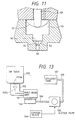
- Fig. 13 is a schematic view showing an ink supply system of an ink-jet type recording apparatus to which the present invention can be applied.
- a print head unit 101 of an ink-jet type is connected to an ink tank 103 through a connecting member 102.
- Ink is supplied from the ink tank 103 to the print head unit 101 through a hollow needle 102a and an ink supply passage 102b of the connecting member 102, so that the print head unit 101 emits ink droplets in accordance with print signals.
- the apparatus shown in Fig. 13 also includes a cap member 104 disposed at non-printing area, which cap member comes into abutment against the nozzle plate of the print head unit 101 by a drive mechanism (not shown) for preventing the nozzle openings from drying.
- the cap member 104 is connected through a tube 108 to a suction pump 105 which is operated by a control device 106 to suck ink from the print head unit 101 through the cap member 104.
- the apparatus shown in Fig. 13 is also provided with an effluent tank 107 connected to an outlet port of the suction pump 105 through a tube 109.
- the recording head may be of any structure such as described in European Patent Publication Nos. 581,531, 609,863, 584,823 and so on.
- a first embodiment of the invention is depicted wherein a container constituting an ink cartridge body, indicated generally at reference numeral 1 is formed with a first wall 1a with an ink supply port 2 formed therein, into which an ink supply needle of a recording head (not shown) may be inserted.
- the space inside container 1 is separated into an ink chamber 4 and an ink supply chamber 5 by a membrane valve seat 3, described hereinafter.
- Membrane valve seat 3 is made of an elastic membrane, such as a rubber membrane, polymeric elastomer membrane or the like, having a resistance to ink, and formed with a membrane through hole 6 in a central portion thereof.
- Membrane valve seat 3 is placed on a step 7 formed in a lower portion of container 1.
- Membrane valve seat 3 is maintained in a stretched state by a valve assembly 9 which engages and holds the periphery of membrane valve seat 3 against step 7.
- valve body 8 is vertically movably inserted into a valve through hole 10 formed through valve assembly 9.
- Valve body 8 has a width that ensures the formation of a gap between valve assembly 9 and valve body 8 through which ink flows, and a length slightly larger than the thickness of valve assembly 9.
- valve body 8 In a normal state, when cartridge 1 is not connected to a recording head undergoing a printing operation, valve body 8 has its lower end placed in elastic contact with membrane valve seat 3 by a valve body support member 11 so as to close the membrane through hole 6 of membrane valve seat 3.
- the lower end of valve body 8 is formed with a curved periphery to form a better seal with membrane valve seat 3.
- Valve assembly 9 is formed with an ink passage 15 in the surface thereof facing away from ink supply port 2 and communicating to valve through hole 10 for directing ink thereto.
- Valve body support member 11 is arranged on and secured at its periphery to the surface of valve assembly 9 on the opposed side of valve assembly 9 to membrane valve seat 3, in a stretched state in order to maintain valve body 8 in elastic contact with membrane valve seat 3, as well as to prevent valve body 8 from lowering below a predetermined position.
- Valve body support member 11 is made of a similar material to that of membrane valve seat 3, and is formed with a support member through hole 12 therein forming ink passage 15. Also, valve body support member 11 supports a top portion 8a of valve body 8 adjacent but spaced from support member through hole 12.
- valve body 8 is formed with annular peripheral groove 8b for receiving the periphery of a mounting aperture 11a in valve support member 11 and a head 8a shaped both to be forced through mounting aperture 11a by elastic deformation thereof due to its rounded top end, and to retain the valve body on the valve body support membrane when mounted thereon.
- membrane valve seat 3, valve body support member 11, and valve body 8 are assembled with and fixed to valve assembly 9 prior to the final construction of container 1, and are incorporated into container 1 by placing the entire assembly on step 7 of container 1 at one time.
- Container 1 has its upper end closed by a lid member 13 having an atmosphere communicating hole 14 formed therethrough.
- lid member 13 On the side of lid member 13 facing the inside of ink chamber 4, lid member 13 is formed with a recess 30 surrounding atmosphere communicating hole 14, a communicating port 32 positioned a predetermined distance away from recess 30, and a narrow groove 31 constituting a capillary channel for maintaining recess 30 and communicating port 32 in fluid communication.
- a flexible membrane 33 is arranged over recess 30 and groove 31 in such a loose state that flexible membrane 33 is maintained a small distance away from communicating hole 14 when lid member 13 is placed on container 1, while one wall of the capillary channel of groove 31 is defined by flexible membrane 33.
- ink supply port 2 When ink supply port 2 is penetrated by an ink supply needle of the recording head (not shown) carried on a carriage (the ink supply port being normally sealed by an ink impermeable closure (not shown) pierceable by the needle in a conventional manner), ink supply chamber 5 is placed in fluid communication via this ink supply needle with the recording head. In this state, flexible membrane 33 of lid member 13 is maintained in a hanging position away from lid member 13 so as to open atmosphere communication hole 14 because of gravity or other pressure difference. Thus, ink chamber 4 communicates with the atmosphere through open atmosphere communicating hole 14, recess 30, groove 31, and communicating port 32.
- ink in ink supply chamber 5 flows through ink supply port 2 into the recording head, whereby the pressure inside ink supply chamber 5 gradually decreases.
- membrane valve seat 3 receives pressure from ink chamber 4 and expands in the direction toward ink supply port 2, by virtue of its elasticity, in the form of an essentially spherical surface having a radius R.
- valve body 8 moves in conjunction with membrane valve seat 3 (FIG.
- ink contained in ink chamber 4 is prohibited from flowing into ink supply chamber 5 which in turn prevents the pressure inside ink supply chamber 5 from increasing excessively, while also preventing the pressure inside ink supply chamber 5 from decreasing excessively. In this manner, the pressure on the recording head is maintained at constant negative pressure with respect to the ink chamber 4.
- membrane valve seat 3 is further elastically expanded toward ink supply port 2.
- Valve body 8 is prevented from lowering below a predetermined position by valve body support member 11, so that valve body 8 is separated from membrane valve seat 3 by a very narrow gap 6a (FIG. 23).
- ink in ink chamber 4 passes through support through hole 12, passage 15, valve through hole 10 and narrow gap 6a formed between valve body 8 and membrane valve seat 3, and flows through membrane through hole 6 into ink supply chamber 5.
- membrane valve seat 3 moves back toward valve body 8 by its elasticity and elastically contacts with valve body 8, whereby narrow gap 6a and membrane through hole 6 are closed by the lower surface of valve body 8. This prohibits ink from flowing from ink chamber 4 into ink supply chamber 5. As a result, the pressure at the ink supply port is maintained at a constant level irrespective of the amount of ink contained in ink chamber 4.
- membrane valve seat 3 Each time the pressure inside ink supply chamber 5 slightly decreases because of ink consumption during a printing operation, membrane valve seat 3 slightly expands toward ink supply port 2 to form a gap between membrane valve seat 3 and valve body 8, through which ink from ink chamber 4 flows into ink supply chamber 5. In this manner, membrane valve seat 3, made of an elastic membrane, is brought into contact with and separated from valve body 8 in accordance with the consumption of ink during printing.
- membrane valve seat 3 made of an elastic membrane, it is possible to remarkably reduce the difference in pressure between the time an ink supply procedure will begin and end, as well as to discharge all ink in ink chamber 4 to the recording head so that none of the ink will be wasted.
- membrane valve seat 3 moves toward ink chamber 4 which is open to the atmosphere. This prevents the pressure inside ink supply chamber 5 from increasing, thus maintaining appropriate negative pressure between ink chamber 4 and recording head irrespective of temperature rise or pressure increase. It is therefore possible to prevent ink from leaking from the recording head due to an increase in pressure.
- membrane valve seat 3 is formed of a rubber membrane having a thickness of 0.04 mm and an effective diameter, i.e., an elastically deformable region of 20 mm.
- a lower limit position of valve body 8 is designed such that the radius R of the spherical surface is 26 mm immediately before ink flows out, i.e., in a critical state with valve body 8.
- FIG. 3 is a graph which depicts the change in fluid pressure value of the ink cartridge according to the invention. It can be understood from FIG. 3 that even if a large amount of ink, for example, five grams per minute of ink, is supplied, the increase in fluid pressure value is small. Thus, ink can be smoothly supplied to the recording head even if a large amount of ink is consumed by the recording head without imparting excessive negative pressure on the recording head.
- ink chamber 4 During the manufacturing and ink filling process, a negative pressure is applied to ink chamber 4 to exhaust air from cartridge 1.
- ink supply port 2 being closed by a filling seal 16
- ink chamber 4 initially achieves a lower pressure than ink supply chamber 5.
- valve body 8 moves toward ink chamber 4 against the elastic force of valve body support member 11 to form a filling gap 12a between membrane valve seat 3 and valve body 8, so that all air can be exhausted from the entire cartridge 1 including ink chamber 4 and ink supply chamber 5, irrespective of the existence of membrane valve seat 3 and valve body 8. This permits the entire cartridge 1, including ink supply chamber 5, to be filled with ink.
- valve body 8 is provided with a flat positioning piece 35 fixed thereto on the side thereof facing valve body support member 11, in the region of valve through hole 10, which abuts the upper peripheral surface of valve body 8 when the lower surface of valve body 8 is brought into contact with membrane valve seat 3.
- positioning piece 35 is maintained in contact with the upper surface of valve assembly 9 and the periphery of valve body 8, and valve body 8 is supported by valve assembly 9 to maintain its posture as vertical as possible.
- FIG. 5 depicts an ink cartridge 300 constructed in accordance with a third embodiment of the invention, like elements being designated by like reference numerals.
- a valve body 20 is inserted into a valve body accommodating chamber 9a formed in valve assembly 9' with spring 21 positioned to urge valve body 20 toward ink supply port 2.
- a lower limit position of valve body 20 is defined by a laterally outwardly extending positioning piece 36 formed on the upper end of valve body 20 abutting a laterally inwardly extending protrusion 9b formed in a lower portion of valve body accommodating chamber 9a. Also, as is shown in FIG.
- ink chamber 4 is selectively maintained in fluid communication with ink supply chamber 5 via through holes 22 and 23, through hole 22 communicating directly between ink chamber 4 and valve body accommodating chamber 9a, which through hole 23 communicates directly between ink chamber 4 and the space between membrane valve seat 3 and has a laterally extending surface groove 23a formed on the side of valve assembly 9' facing said membrane valve seat 3 extending between through hole 23 and valve body accommodating chamber 9a.
- membrane valve seat 3 in response to decreased pressure inside ink supply chamber 5, receives pressure from ink chamber 4 and expands toward supply port 2, by virtue of its elasticity, in the form of an essentially spherical surface having a radius R.
- valve body 20 moves in conjunction with membrane valve seat 3 by the resilient force of spring 21, and positioning piece 36 abuts protrusion 9b to maintain valve body 20 in a vertical posture (FIG. 6A)
- ink is prohibited from flowing from ink chamber 4 into ink supply chamber 5 while preventing the pressure inside ink supply chamber 5 from decreasing excessively.
- membrane valve seat 3 abuts valve body 20 irrespective of any vibrations or swinging motion of the cartridge due to the movement of the carriage, so that ink pressure on the recording head is maintained at constant negative pressure with respect to ink chamber 4.
- membrane valve seat 3 is further expanded toward ink supply port 2.
- Valve body 20 is prevented from lowering below a predetermined position by protrusion 9b of valve accommodating chamber 9a, so that valve body 8 is separated from membrane valve seat 3 by very narrow gap 6a (FIG. 6B).
- ink in ink chamber 4 passes through narrow gap 6a formed between valve body 20 and membrane valve seat 3 and flows through membrane through hole 6 into ink supply chamber 5.
- membrane valve seat 3 moves back toward valve body 20 by its elasticity and elastically contacts with valve body 20, whereby narrow gap 6a and membrane through hole 6 are closed by the lower surface of valve body 20. This prohibits ink from flowing from ink chamber 4 into ink supply chamber 5. As a result, the pressure at ink supply port 2 is maintained at a constant level irrespective of the amount of ink contained in the ink chamber 4.
- ink chamber 4 During the manufacturing and ink filling process, a negative pressure is applied to ink chamber 4 to exhaust air from cartridge 300. With ink supply port 2 being closed by filling seal 16, ink chamber 4 achieves a lower pressure than ink supply chamber 5.
- valve body 20 moves toward ink chamber 4 against force of spring 21 to form a filling gap 12a between membrane valve seat 3 and valve body 20, so that all air can be exhausted from the entire cartridge 300, irrespective of the existence of membrane valve seat 3 and valve body 20. This permits the entire cartridge 300 including ink supply chamber 5 to be filled with ink.
- an elastic member (spring 21) for bringing valve body 20 into contact with membrane valve seat 3 is incorporated in valve assembly 9'.
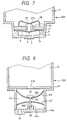
- an ink cartridge body 400 may be formed with a valve body 37, as shown in FIG. 7, which may be formed in a mushroom shape, such that a cap portion 37a functions as a positioning piece and as a stopper, and a spring 38, mounted at its periphery to the top surface of valve assembly 9", may be used to urge the top of valve body 37 toward membrane valve seat 3. Since valve body 37 and spring 38 can be mounted from the outside of valve assembly 9", the assembling work of the ink tank cartridge can be simplified.
- a through hole 9c is formed in valve assembly 9" communicating between ink chamber 4 and the space between the lower surface of valve assembly 9" and membrane valve seat 3.
- FIG. 8 depicts an ink cartridge 500 constructed in accordance with a fifth embodiment of the invention, like elements being designated by like reference numerals. While in the foregoing embodiments, the spring is arranged above the valve body, it is apparent that similar effects can be produced when ink cartridge 500 is separated into an ink chamber 42 and an ink supply chamber 43 by a partition 41 formed with a partition through hole 41a.
- Ink supply chamber 43 houses a membrane valve seat 44 and a valve body 46 comprising an elongated portion 46b extending through a membrane through hole 45 and head portion having a spherically formed lower surface 46a for sealing membrane through hole 45 formed through membrane valve seat 44.
- Elongated portion 46b extends from and perpendicular to lower surface 46a and penetrating membrane through hole 45 of membrane valve seat 44. Elongated portion 46b extends through and is supported on a spring 47 which always urges elongated portion 46b, and therefore valve body 46, in the direction of an ink supply port 49 and a guide hole 48, which receives the lower end of support member 46b to position valve body 46 in a vertical posture formed in a wall of the cartridge as shown in FIG. 8.
- Guide hole 48 is defined by an upwardly projecting annular wall 43a formed in a bottom wall 49a of ink cartridge 500.
- valve body 46 is always urged toward wall 49a, in which ink supply port 49 is formed, by spring 47 to maintain a stable posture, irrespective of any force generated by ink, ink can be stably supplied to the recording head irrespective of any vibrations or swinging motion of ink in cartridge 500 due to the movement of the carriage.
- membrane valve seat 44 moves toward ink supply port 49, thereby maintaining the pressure below valve seat 44.
- elongated portion 46b engages the bottom of guide hole 48, the movement of valve body 46 is stopped. Thereafter, any additional consumption of ink moves membrane valve seat 44 away from lower surface 46a of support member 46, thereby exposing a membrane through hole 45, and allowing ink to pass therethrough.
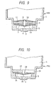
- FIG. 9 depicts ink cartridge 600 constructed in accordance with a sixth embodiment of the invention, like elements being designated by like reference numerals.
- a level stabilizing membrane 50 is made of a soft porous membrane or lattice membrane which can move in conjunction with membrane valve seat 3 is provided.
- a porous member through hole 51 is formed through a region opposite valve body 8 of stabilizing membrane 50, and a lower end portion of valve body 8 is fit into porous member through hole 51.
- Stabilizing membrane 50 has its periphery secured to valve assembly 9 and a central portion thereof secured to valve body 8.
- membrane valve seat 3 separates from valve body 8 so that ink in ink chamber 4 flows through porous member through hole 51 of level stabilizing membrane 50 into ink supply chamber 5.
- the ink in ink chamber 4 may violently swing near valve body 8 due to the movement of the carriage, However, since the ink passes through membrane through hole 6 of membrane valve seat 3 after fluctuations in pressure of the ink have been suppressed by level stabilizing membrane 50 as much as possible, the ink pressure on the recording head is maintained at a constant level irrespective of the amount of ink remaining in ink chamber 4.
- an elastic member (valve body support member 11) is used to elastically maintain contact between the valve body 8 and membrane valve seat 3, the elastic member for elastically contacting valve body 8 with membrane valve seat 3 may be unnecessary if the elastic force of membrane valve seat-3 is actively utilized.
- FIG. 10 depicts an ink cartridge 700 constructed in accordance with a seventh embodiment of the invention, like elements being designed by like reference numerals.
- This seventh embodiment does not require an elastic member for elastically urging a valve body to maintain contact with a membrane valve seat.
- a membrane valve seat 24 is formed with a membrane through hole 25 formed therein in a region opposing a valve body 28, hereinafter described, and has its periphery secured by a valve assembly 27.
- Valve body 28 is unmovably fixed to valve assembly 27 in a position perpendicular thereto.
- Ink chamber 4 is selectively maintained in fluid communication with ink supply chamber 5 via a communicating hole 29 in the form of a radial slit extending from valve body 28.
- membrane valve seat 24 When a pressure difference between ink chamber 4 and ink supply chamber 5 is equal to or less than a predetermined value, membrane valve seat 24, through its own elasticity, brings membrane through hole 25 into contact with valve body 28 to stop the outflow of ink from ink chamber 4 to ink supply chamber 5.
- membrane valve seat 24 extends toward ink supply port 2 in the form of a spherical surface, whereby membrane through. hole 25 is removed from contact with valve body 28, and accordingly ink flows from ink chamber 4 into ink supply chamber 5 via membrane through hole 25.
- membrane valve seat 24 elastically contacts with valve body 28, against the pressure difference between ink chamber 4 and ink supply chamber 5, to stop the outflow of ink from ink chamber 4 to ink supply chamber 5.
- FIG. 11 depicts an ink cartridge constructed in accordance with an eighth embodiment of the invention, like elements being designated by like reference numerals.
- the ink cartridge of this eighth embodiment prevents air from entering a recording head at the time the recording head has depleted all of the ink in the ink cartridge.
- a downwardly tapered conical valve seat 54 is formed in a connecting region between an ink supply port 52 and an ink supply chamber 53.
- a spherical floating valve 55 which floats by a floating force produced by the buoyancy of spherical floating valve 55, is accommodated in conical valve seat 54.
- a valve retention plate 56 made of an ink transmissible material such as a screen, to complete a shielding valve.
- a membrane valve seat 57 is also arranged in selectable contact with a valve body 58 for controlling the flow of ink thereto from an ink chamber (not shown).
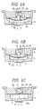
- floating valve 55 When the ink cartridge is mounted on the recording head, floating valve 55 floats upward and is retained against valve retention plate 56 by a floating force to open ink supply port 52 through which ink is supplied to the recording head. As ink in the cartridge is consumed during printing operations, the level of ink in the cartridge is reduced in the vicinity of ink supply port 52. Floating valve 55 looses its floating force because of the absence of ink, and therefore comes into contact with valve seat 54 to close ink supply port 52 (as indicated by the broken line in FIG. 11), Even if printing is continued with the almost exhausted cartridge, the closed ink supply port 52 prohibits air from entering the recording head, thus preventing defective printing.
- an ink cartridge once mounted on a recording head, is not removed until ink contained in the ink chamber is depleted.
- the ink cartridge may be removed from the recording head by an erroneous manipulation. If a once mounted cartridge is removed from the recording head, ink supply port 52 is open to the atmosphere and may allow air to enter the ink supply chamber and the ink chamber, which may adversely affect the flow of ink during the recording operation.
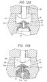
- FIGS. 12A and 12B depict an ink tank cartridge constructed in accordance with a ninth embodiment of the present invention, like elements being designated by like refersnce numerals.
- the ink cartridge of this ninth embodiment prevents air from entering the cartridge if the ink cartridge is removed before it is depleted.
- a telescopical valve body 60 is arranged in an ink supply port 61, and is formed with an ink supply needle fitting hole 62 in its lower portion into which an ink supply needle 70 may be removably fitted.
- Valve body 60 is also formed with a communicating hole 64 for connecting an ink supply chamber 63 with ink supply needle fitting hole 62 when valve body 60 moves to an upward limited position.
- valve body 60 which is formed with a radially extending, elastic periphery 60a, is maintained in elastic contact with a bottom surface 63a of ink supply chamber 63 by its elasticity to reliably prevent the outflow of ink from ink supply chamber 63.
- valve body 60 When ink supply needle 70 is inserted into fitting hole 62, valve body 60 is separated from bottom surface 63a of ink supply chamber 63 and extends to the upward limited position, while communicating hole 64 is exposed to ink supply chamber 63 (FIG. 12B). This causes ink supply chamber 63 to be placed in fluid communication with an ink passage 70a of ink supply needle 70 through communicating hole 64, and a needle communicating hole 70b, whereby ink in ink supply chamber 63 flows into ink supply needle 70 and is consequently supplied to the recording head. When the ink cartridge mounted on the recording head is removed, valve body 60 moves toward the bottom 63A of FIG. 12A to close ink supply port 61 and hence ink supply chamber 63. This prevents the outflow of ink from ink supply chamber 63 as well as the entrance of air into ink supply chamber 63.
- a container formed with an ink supply port in one of its walls is separated by a membrane valve seat made of an elastic thin membrane and formed with a through hole in the central portion thereof.
- An ink chamber is formed in the portion of the cartridge not adjacent the ink supply port, and an ink supply chamber is formed in the portion of the cartridge adjacent the ink supply port, and a valve body is positioned in opposition to the through hole.
- the membrane valve seat receives a pressure difference over a large area thereof because of the consumption of ink and allows ink to flow from the ink chamber in response to a small amount of consumed ink.
- the recording head can be supplied with ink without imparting excessive negative pressure on the recording head, and ink in the ink chamber can be discharged to the recording head without waste.
- the membrane valve body displaces toward the ink chamber to release the pressure increased by the pressure rise inside the ink supply chamber communicating with the recording head to the ink chamber. It is therefore possible to prevent ink from leaking when the printer is not in use.
- negative pressure suitable for printing is maintained between the recording head and the ink cartridge to ensure stable printing.
- the valve function can be reliably performed irrespective of any swinging motion or vibrations of ink in the ink chamber caused by the movement of the carriage, thus making it possible to maintain a pressure difference between the ink cartridge and the recording head irrespective of the movement of the carriage to achieve an improvement in printing quality.
- an ink cartridge for an ink jet recording apparatus comprising a container for storing ink having at least a first wall; an ink supply port formed through the first wall for supplying ink to the exterior of the container; a sealing valve retained in the ink supply port, the sealing valve being formed with a communicating hole formed therein, the sealing valve being displacable between a first position at which the sealing valve is biased to close the ink supply port and a second position at which the ink supply port is placed in fluid communication with the interior of the container to permit flow of ink from the interior of the container, the sealing valve being positioned to be displacable from the first position to the second position when the ink cartridge is mounted on the ink jet recording apparatus.
- an ink cartridge for an ink jet recording apparatus comprising: a container for storing ink having at least a first wall; an ink supply port formed through the first wall for supplying ink to the exterior of the container; a sealing valve retained in the ink supply port, the sealing valve being formed with a communicating hole formed therein, the sealing valve being displacable between a first position at which the sealing valve is biased to close the ink supply port and a second position at which the ink supply port is placed in fluid communication with the interior of the container to permit flow of ink from the interior of the container, the sealing valve being positioned to be displacable from the first position to the second position when the ink cartridge is mounted on the ink jet recording apparatus.
- the ink cartridge for an ink jet recording apparatus is further provided such that the sealing valve is dimensioned to receive an ink supply needle when the ink cartridge is mounted on a recording head.
- the ink cartridge for an ink jet recording apparatus is further provided such that the sealing valve is positioned within the ink supply port, the sealing valve closing the ink supply port when only a minimal amount of ink remains in the container.
- the ink cartridge for an ink jet recording apparatus is further provided such that the sealing valve further comprises a conical valve seat having an open and a restricted end, the open end extending toward the interior of the chamber; a floating valve positioned in the open end of the conical valve seat; and a valve retaining plate positioned adjacent the conical valve seat and retaining the floating valve in the open end of the valve seat.
- an ink jet recording apparatus comprising a print head for emitting ink droplets in accordance with print signals; an ink supply member engaging with the print head; and an ink cartridge connected to the print head through the ink supply member.
Priority Applications (1)
| Application Number | Priority Date | Filing Date | Title |
|---|---|---|---|
| EP20050025214 EP1640168A3 (fr) | 1994-10-26 | 1995-10-26 | Cartouche d'encre pour imprimante à jet d'encre |
Applications Claiming Priority (6)
| Application Number | Priority Date | Filing Date | Title |
|---|---|---|---|
| JP28729294 | 1994-10-26 | ||
| JP28729294 | 1994-10-26 | ||
| JP25810195A JPH08174860A (ja) | 1994-10-26 | 1995-09-11 | インクジェットプリンタ用インクカートリッジ |
| JP25810195 | 1995-09-11 | ||
| EP19950116908 EP0709207B1 (fr) | 1994-10-26 | 1995-10-26 | Cassette d'encre pour imprimante à jet d'encre |
| EP20000106742 EP1013443B1 (fr) | 1994-10-26 | 1995-10-26 | Cartouche d'encre pour imprimante à jet d'encre |
Related Parent Applications (3)
| Application Number | Title | Priority Date | Filing Date |
|---|---|---|---|
| EP95116908.5 Division | 1995-10-26 | ||
| EP20000106742 Division EP1013443B1 (fr) | 1994-10-26 | 1995-10-26 | Cartouche d'encre pour imprimante à jet d'encre |
| EP00106742.0 Division | 2000-03-29 |
Related Child Applications (1)
| Application Number | Title | Priority Date | Filing Date |
|---|---|---|---|
| EP20050025214 Division EP1640168A3 (fr) | 1994-10-26 | 1995-10-26 | Cartouche d'encre pour imprimante à jet d'encre |
Publications (4)
| Publication Number | Publication Date |
|---|---|
| EP1279513A2 true EP1279513A2 (fr) | 2003-01-29 |
| EP1279513A3 EP1279513A3 (fr) | 2003-04-02 |
| EP1279513B1 EP1279513B1 (fr) | 2006-05-10 |
| EP1279513B9 EP1279513B9 (fr) | 2006-08-30 |
Family
ID=26543543
Family Applications (7)
| Application Number | Title | Priority Date | Filing Date |
|---|---|---|---|
| EP19950116908 Expired - Lifetime EP0709207B1 (fr) | 1994-10-26 | 1995-10-26 | Cassette d'encre pour imprimante à jet d'encre |
| EP20020024288 Expired - Lifetime EP1279515B1 (fr) | 1994-10-26 | 1995-10-26 | Cartouche d'encre pour imprimante à jet d'encre |
| EP20020024286 Expired - Lifetime EP1279513B9 (fr) | 1994-10-26 | 1995-10-26 | Cartouche d'encre pour imprimante à jet d'encre |
| EP20020024287 Expired - Lifetime EP1279514B1 (fr) | 1994-10-26 | 1995-10-26 | Cartouche d'encre pour imprimante à jet d'encre |
| EP20000106743 Expired - Lifetime EP1010536B1 (fr) | 1994-10-26 | 1995-10-26 | Cassette d'encre pour imprimante à jet d'encre |
| EP20000106742 Expired - Lifetime EP1013443B1 (fr) | 1994-10-26 | 1995-10-26 | Cartouche d'encre pour imprimante à jet d'encre |
| EP20050025214 Withdrawn EP1640168A3 (fr) | 1994-10-26 | 1995-10-26 | Cartouche d'encre pour imprimante à jet d'encre |
Family Applications Before (2)
| Application Number | Title | Priority Date | Filing Date |
|---|---|---|---|
| EP19950116908 Expired - Lifetime EP0709207B1 (fr) | 1994-10-26 | 1995-10-26 | Cassette d'encre pour imprimante à jet d'encre |
| EP20020024288 Expired - Lifetime EP1279515B1 (fr) | 1994-10-26 | 1995-10-26 | Cartouche d'encre pour imprimante à jet d'encre |
Family Applications After (4)
| Application Number | Title | Priority Date | Filing Date |
|---|---|---|---|
| EP20020024287 Expired - Lifetime EP1279514B1 (fr) | 1994-10-26 | 1995-10-26 | Cartouche d'encre pour imprimante à jet d'encre |
| EP20000106743 Expired - Lifetime EP1010536B1 (fr) | 1994-10-26 | 1995-10-26 | Cassette d'encre pour imprimante à jet d'encre |
| EP20000106742 Expired - Lifetime EP1013443B1 (fr) | 1994-10-26 | 1995-10-26 | Cartouche d'encre pour imprimante à jet d'encre |
| EP20050025214 Withdrawn EP1640168A3 (fr) | 1994-10-26 | 1995-10-26 | Cartouche d'encre pour imprimante à jet d'encre |
Country Status (8)
| Country | Link |
|---|---|
| US (6) | US6000788A (fr) |
| EP (7) | EP0709207B1 (fr) |
| JP (1) | JPH08174860A (fr) |
| KR (1) | KR0167405B1 (fr) |
| CN (6) | CN1057491C (fr) |
| DE (6) | DE69534829T2 (fr) |
| HK (6) | HK1028972A1 (fr) |
| TW (1) | TW370008U (fr) |
Families Citing this family (169)
| Publication number | Priority date | Publication date | Assignee | Title |
|---|---|---|---|---|
| JP3582592B2 (ja) * | 2001-04-03 | 2004-10-27 | セイコーエプソン株式会社 | インクカートリッジ、及びインクジェット記録装置 |
| US6183076B1 (en) * | 1992-04-02 | 2001-02-06 | Hewlett-Packard Company | Printer having multi-chamber print cartridges and off-carriage regulator |
| JPH08174860A (ja) * | 1994-10-26 | 1996-07-09 | Seiko Epson Corp | インクジェットプリンタ用インクカートリッジ |
| DE19545775C2 (de) * | 1995-12-07 | 1999-03-25 | Pelikan Produktions Ag | Flüssigkeitspatrone, insbesondere Tintenpatrone für einen Druckkopf eines Ink-Jet-Printers |
| DE69733176T2 (de) | 1996-02-21 | 2006-02-16 | Seiko Epson Corp. | Tintenkartusche |
| US6130694A (en) * | 1996-05-13 | 2000-10-10 | Hewlett-Packard Company | Regulator assembly for modulating fluid pressure within an ink-jet printer |
| US5988802A (en) * | 1996-08-30 | 1999-11-23 | Hewlett-Packard Company | Off-axis ink supply with pressurized ink tube for preventing air ingestion |
| KR100209516B1 (ko) * | 1997-02-05 | 1999-07-15 | 윤종용 | 잉크젯 프린트 헤드의 잉크 저장 장치 및 방법 |
| JP4141523B2 (ja) * | 1997-03-19 | 2008-08-27 | セイコーエプソン株式会社 | インク供給流路の弁装置 |
| US6692117B1 (en) | 1997-07-14 | 2004-02-17 | Owens-Illinois Closure Inc. | Liquid containment and dispensing device with improved flow control valve |
| CA2248434A1 (fr) * | 1997-09-30 | 1999-03-30 | Asahi Kogaku Kogyo Kabushiki Kaisha | Imprimante a transfert d'encre |
| JPH11157092A (ja) | 1997-11-26 | 1999-06-15 | Bridgestone Corp | インクジェットプリンタ用部材の製造方法 |
| WO1999041083A1 (fr) | 1998-02-13 | 1999-08-19 | Seiko Epson Corporation | Imprimante a jet d'encre, sous-unite reservoir pour ladite imprimante, et procede permettant de retablir la capacite de decharge des gouttelettes d'encre |
| SG100698A1 (en) | 1998-05-13 | 2003-12-26 | Seiko Epson Corp | Ink cartridge for ink-jet printing apparatus |
| EP1254776B1 (fr) * | 1998-05-18 | 2004-03-10 | Seiko Epson Corporation | Appareil d'impression à jet d'encre et cartouche d'encre correspondante |
| DE69926954T2 (de) * | 1998-06-16 | 2006-03-02 | Bridgestone Corp. | Zuführventil |
| US6550498B2 (en) * | 1998-06-16 | 2003-04-22 | Seiko Epson Corporation | Fluid supply valve |
| DE69943417D1 (de) * | 1998-07-15 | 2011-06-16 | Seiko Epson Corp | Tintenzufuhreinheit |
| US6299296B2 (en) * | 1998-07-31 | 2001-10-09 | Hewlett Packard Company | Sealing member for a fluid container |
| ATE364508T1 (de) | 1999-04-08 | 2007-07-15 | Seiko Epson Corp | Tintenstrahlaufzeichnungsgerät und steuerverfahren für die reinigung des eingebauten aufzeichnungskopfes |
| US6799820B1 (en) * | 1999-05-20 | 2004-10-05 | Seiko Epson Corporation | Liquid container having a liquid detecting device |
| JP2001199082A (ja) | 1999-10-08 | 2001-07-24 | Seiko Epson Corp | インクカートリッジ、インクジェット記録装置、及びインクカートリッジの装着方法 |
| GB9925988D0 (en) * | 1999-11-03 | 2000-01-12 | Dynamic Cassette Int | An ink cartridge |
| EP1170135B1 (fr) | 2000-01-18 | 2006-04-05 | Seiko Epson Corporation | Cartouche d'encre, dispositif enregistreur a jet encre utilisant cette cartouche et procede de commande de nettoyage pour tete enregistreuse du dispositif enregistreur |
| US6508547B2 (en) * | 2000-01-31 | 2003-01-21 | Hewlett-Packard Company | Replaceable ink container for an inkjet printing system |
| KR100388332B1 (ko) | 2000-02-16 | 2003-06-25 | 세이코 엡슨 가부시키가이샤 | 잉크젯 기록 장치용 잉크 카트리지, 접속 유닛 및 잉크젯기록 장치 |
| AU2001248230B2 (en) * | 2000-04-03 | 2005-05-26 | Unicorn Image Products Co. Ltd. Of Zhuhai | An ink cartridge and a method and device for filling the ink cartridge |
| US20030107626A1 (en) * | 2000-08-16 | 2003-06-12 | Xiao Qingguo | Ink cartridge having bellows valve, ink filling method and apparatus used thereof |
| US6935730B2 (en) * | 2000-04-03 | 2005-08-30 | Unicorn Image Products Co. Ltd. Of Zhuhai | One-way valve, valve unit assembly, and ink cartridge using the same |
| JP2002001988A (ja) | 2000-04-18 | 2002-01-08 | Canon Aptex Inc | インクタンクおよびインクジェットカートリッジ |
| US6837575B2 (en) * | 2000-07-07 | 2005-01-04 | Seiko Epson Corporation | Ink feed unit for ink jet recorder and diaphragm valve |
| US20050243147A1 (en) * | 2000-10-12 | 2005-11-03 | Unicorn Image Products Co. Ltd. | Ink cartridge having bellows valve, ink filling method and apparatus used thereof |
| CA2359434C (fr) * | 2000-10-20 | 2005-05-03 | Seiko Epson Corporation | Imprimante "ink jet" et cartouche a encre |
| ATE492400T1 (de) * | 2000-10-20 | 2011-01-15 | Seiko Epson Corp | Tintenpatrone für tintenstrahlaufzeichnungsgerät |
| EP1481807B2 (fr) | 2000-10-20 | 2010-11-10 | Seiko Epson Corporation | Dispositif d'enregistrement et cartouche d'encre |
| GB2368557A (en) * | 2000-11-03 | 2002-05-08 | Opportunity Europ Limimted | Ink cartridge including a float valve disposed in the ink outlet chamber thereof |
| JP4635330B2 (ja) * | 2000-12-07 | 2011-02-23 | ブラザー工業株式会社 | インクジェットプリンタ |
| MXPA03006804A (es) | 2001-01-31 | 2004-10-15 | Bridgestone Corp | Miembro elastico para aparato de registro de chorro de tinta, tanque de tinta y aparato de registro de chorro de tinta. |
| JP4673983B2 (ja) * | 2001-01-31 | 2011-04-20 | 株式会社ブリヂストン | インクジェット記録装置用弾性部材、インクタンク及びインクジェット記録装置 |
| JP4673992B2 (ja) * | 2001-04-02 | 2011-04-20 | 株式会社ブリヂストン | インクジェット記録装置用弾性部材、インクタンク及びインクジェット記録装置 |
| WO2002061308A1 (fr) | 2001-01-31 | 2002-08-08 | Bridgestone Corporation | Joint integre au couvercle |
| JP4673982B2 (ja) * | 2001-01-31 | 2011-04-20 | 株式会社ブリヂストン | インクジェット記録装置用弾性部材、インクタンク及びインクジェット記録装置 |
| JP4193435B2 (ja) * | 2002-07-23 | 2008-12-10 | ブラザー工業株式会社 | インクカートリッジ、および、そのインク充填方法 |
| CN2649337Y (zh) * | 2001-05-17 | 2004-10-20 | 精工爱普生株式会社 | 墨盒 |
| CN100393521C (zh) * | 2001-05-17 | 2008-06-11 | 精工爱普生株式会社 | 往墨盒中注射墨水的方法 |
| JP2003034042A (ja) * | 2001-05-17 | 2003-02-04 | Seiko Epson Corp | インクカートリッジ |
| ATE367270T1 (de) | 2001-05-17 | 2007-08-15 | Seiko Epson Corp | Tintenkartusche und herstellungsverfahren einer tintenkartusche |
| US6477956B1 (en) * | 2001-08-10 | 2002-11-12 | Sonoco Development, Inc. | Ink cartridge with self-closing valve |
| DE10141817B4 (de) * | 2001-08-27 | 2005-03-03 | Eppendorf Ag | Membranvorrichtung zum Aufnehmen von Proben und Verfahren zur Herstellung einer Vorrichtung |
| ATE348006T1 (de) * | 2001-10-31 | 2007-01-15 | Print Rite Unicorn Image Prod | Tintenpatrone für einen drucker |
| CN100374303C (zh) | 2001-11-08 | 2008-03-12 | 精工爱普生株式会社 | 墨盒及记录装置 |
| JPWO2003041963A1 (ja) * | 2001-11-12 | 2005-03-03 | セイコーエプソン株式会社 | インクカートリッジ |
| EP1445105B1 (fr) | 2001-11-12 | 2010-01-13 | Seiko Epson Corporation | Injecteur de liquide |
| CN2544940Y (zh) * | 2002-04-27 | 2003-04-16 | 珠海纳思达电子科技有限公司 | 打印机墨盒 |
| JP3901019B2 (ja) | 2002-06-04 | 2007-04-04 | ブラザー工業株式会社 | インクカートリッジ |
| JP3891150B2 (ja) * | 2002-07-09 | 2007-03-14 | セイコーエプソン株式会社 | 液体カートリッジおよび液体収容体 |
| JP3991853B2 (ja) | 2002-09-12 | 2007-10-17 | セイコーエプソン株式会社 | インクカートリッジ |
| US6984030B2 (en) | 2002-11-13 | 2006-01-10 | Seiko Epson Corporation | Ink cartridge and method of regulating fluid flow |
| GB0226708D0 (en) * | 2002-11-15 | 2002-12-24 | Avecia Ltd | Compounds |
| EP2093063A1 (fr) * | 2002-12-10 | 2009-08-26 | Seiko Epson Corporation | Cartouche de liquide |
| CN2614901Y (zh) * | 2003-01-14 | 2004-05-12 | 珠海天威飞马打印耗材有限公司 | 密封圈、墨盒 |
| US6951387B2 (en) * | 2003-01-15 | 2005-10-04 | Xerox Corporation | Ink tank with capillary member |
| US6877849B2 (en) * | 2003-01-23 | 2005-04-12 | Hewlett-Packard Development Company, L.P. | Printing system with high volumetric ink container vessel |
| ATE358590T1 (de) * | 2003-02-04 | 2007-04-15 | Brother Ind Ltd | Luftblasenentfernung bei einem tintenstrahldrucker |
| US8454135B2 (en) | 2003-02-04 | 2013-06-04 | Brother Kogyo Kabushiki Kaisha | Air bubble removal in an ink jet printer |
| ATE465879T1 (de) | 2003-03-05 | 2010-05-15 | Seiko Epson Corp | Verfahren zur herstellung eines flüssigkeitsbehälters |
| JP3873910B2 (ja) * | 2003-03-05 | 2007-01-31 | セイコーエプソン株式会社 | 液体収容袋及び液体噴射装置 |
| EP1468748A1 (fr) * | 2003-04-15 | 2004-10-20 | Microflow Engineering SA | Générateur de gouttelettes de liquide et sa buse |
| JP3848298B2 (ja) | 2003-05-22 | 2006-11-22 | キヤノン株式会社 | インクタンク |
| US7401367B2 (en) * | 2003-05-28 | 2008-07-22 | Graco Children's Products Inc. | Playard |
| US6865756B2 (en) * | 2003-05-28 | 2005-03-15 | Graco Children's Products Inc. | Playard |
| US6837577B1 (en) * | 2003-06-18 | 2005-01-04 | Lexmark International, Inc. | Ink source regulator for an inkjet printer |
| US7163282B2 (en) * | 2003-06-20 | 2007-01-16 | Seiko Epson Corporation | Valve unit and liquid ejecting apparatus |
| US7699449B2 (en) * | 2003-06-20 | 2010-04-20 | Seiko Epson Corporation | Liquid injection apparatus and method for driving the same |
| JP2005047207A (ja) * | 2003-07-31 | 2005-02-24 | Shinko Electric Ind Co Ltd | インクジェット方式の印刷機 |
| CN100398612C (zh) * | 2003-10-01 | 2008-07-02 | 日本化药株式会社 | 偶氮化合物、含有它的染料水溶液、油墨及其用途 |
| US7159974B2 (en) * | 2003-10-06 | 2007-01-09 | Lexmark International, Inc. | Semipermeable membrane for an ink reservoir and method of attaching the same |
| US20050095139A1 (en) * | 2003-10-30 | 2005-05-05 | A.O. Smith Corporation | Apparatus and method for containing and regulating the pressure in a pressure vessel |
| US7278722B2 (en) * | 2003-11-25 | 2007-10-09 | Brother Kogyo Kabushiki Kaisha | Ink cartridge |
| JP2005186344A (ja) * | 2003-12-24 | 2005-07-14 | Seiko Epson Corp | 弁装置及び液体噴射装置 |
| JP4525080B2 (ja) * | 2004-01-14 | 2010-08-18 | セイコーエプソン株式会社 | 液体収容体の液体充填方法 |
| US20050157112A1 (en) | 2004-01-21 | 2005-07-21 | Silverbrook Research Pty Ltd | Inkjet printer cradle with shaped recess for receiving a printer cartridge |
| US7448734B2 (en) * | 2004-01-21 | 2008-11-11 | Silverbrook Research Pty Ltd | Inkjet printer cartridge with pagewidth printhead |
| US7188937B2 (en) * | 2004-01-29 | 2007-03-13 | Hewlett-Packard Development Company, L.P. | Printing-fluid venting assembly |
| DE602005024741D1 (de) * | 2004-02-09 | 2010-12-30 | Brother Ind Ltd | Tintenpatrone |
| JP4746843B2 (ja) * | 2004-03-15 | 2011-08-10 | ブラザー工業株式会社 | インクカートリッジ及びインクジェット記録装置 |
| US20050219281A1 (en) | 2004-03-24 | 2005-10-06 | Takeo Seino | Attachment and liquid supplying |
| JP4731136B2 (ja) * | 2004-07-05 | 2011-07-20 | 株式会社ニックス | 液体送受用ジョイント装置 |
| US7431435B2 (en) * | 2004-08-06 | 2008-10-07 | Matthew Grant Lopez | Systems and methods for varying dye concentrations |
| JP4742735B2 (ja) * | 2004-09-24 | 2011-08-10 | セイコーエプソン株式会社 | 液体噴射装置 |
| JP4258462B2 (ja) * | 2004-11-19 | 2009-04-30 | セイコーエプソン株式会社 | 圧力調整弁、機能液供給装置および描画装置 |
| US20060203048A1 (en) * | 2005-03-14 | 2006-09-14 | Scheffelin Joseph E | Plug |
| JP4725265B2 (ja) * | 2005-03-31 | 2011-07-13 | ブラザー工業株式会社 | インクジェット記録装置 |
| JP4725182B2 (ja) * | 2005-04-28 | 2011-07-13 | セイコーエプソン株式会社 | 液体供給システムの製造方法及び液体供給システム |
| CN2920655Y (zh) * | 2005-06-10 | 2007-07-11 | 珠海纳思达电子科技有限公司 | 一种通用打印机墨盒 |
| CN2832528Y (zh) * | 2005-08-02 | 2006-11-01 | 珠海纳思达电子科技有限公司 | 一种通用打印机墨盒 |
| US20070035596A1 (en) * | 2005-08-10 | 2007-02-15 | Lexmark International, Inc. | Ink jet cartridge |
| US7637588B2 (en) * | 2005-10-11 | 2009-12-29 | Silverbrook Research Pty Ltd | Printhead maintenance assembly comprising maintenance roller and cleaning mechanism |
| US7753472B2 (en) * | 2005-10-11 | 2010-07-13 | Silverbrook Research Pty Ltd | Printhead maintenance station having rotational pad engagement |
| US7686419B2 (en) * | 2005-10-11 | 2010-03-30 | Silverbrook Research Pty Ltd | Method of maintaining a printhead using a roller action |
| US7506958B2 (en) * | 2005-10-11 | 2009-03-24 | Silverbrook Research Pty Ltd | Printhead maintenance station |
| US20070103520A1 (en) * | 2005-11-04 | 2007-05-10 | U Colour International Co., Ltd. | Interior pressure self-adjustable ink supply cartridge structure |
| JP2007160926A (ja) | 2005-11-18 | 2007-06-28 | Seiko Epson Corp | 液滴吐出装置 |
| JP4994648B2 (ja) * | 2005-11-30 | 2012-08-08 | キヤノン株式会社 | インクタンクおよびこれを用いるインクジェット記録装置 |
| US7556364B2 (en) | 2005-12-05 | 2009-07-07 | Silverbrook Research Pty Ltd | Ink cartridge with self sealing outlet valve |
| US7357496B2 (en) * | 2005-12-05 | 2008-04-15 | Silverbrook Research Pty Ltd | Inkjet printhead assembly with resilient ink connectors |
| JP2007182055A (ja) * | 2005-12-06 | 2007-07-19 | Seiko Epson Corp | 液体収容容器 |
| JP4899683B2 (ja) * | 2005-12-13 | 2012-03-21 | セイコーエプソン株式会社 | 差圧弁ユニット |
| US20070170528A1 (en) * | 2006-01-20 | 2007-07-26 | Aaron Partridge | Wafer encapsulated microelectromechanical structure and method of manufacturing same |
| WO2007109990A1 (fr) * | 2006-03-24 | 2007-10-04 | Print-Rite Technology Development Co., Ltd Of Zhuhai | Corps de soupape, ensemble soupape et cartouche d'encre |
| DE102006026258A1 (de) | 2006-06-02 | 2007-12-06 | Artech Gmbh Design + Production In Plastic | Tintenkartusche |
| US7703903B2 (en) * | 2006-07-10 | 2010-04-27 | Silverbrook Research Pty Ltd | Ink reservoir for inkjet printhead |
| JP5055889B2 (ja) | 2006-08-11 | 2012-10-24 | セイコーエプソン株式会社 | 液体収容体の製造方法 |
| US8163075B2 (en) | 2006-10-31 | 2012-04-24 | Sensient Colors Llc | Inks comprising modified pigments and methods for making and using the same |
| US8322835B2 (en) | 2007-02-19 | 2012-12-04 | Seiko Epson Corporation | Sealing structure of fluid container, and method of manufacturing and reusing fluid container |
| JP4894557B2 (ja) * | 2007-02-28 | 2012-03-14 | ブラザー工業株式会社 | インクカートリッジのインク充填方法 |
| JP2008230024A (ja) | 2007-03-20 | 2008-10-02 | Fujifilm Corp | 平版印刷版原版および平版印刷版の作製方法 |
| JP4345833B2 (ja) * | 2007-03-20 | 2009-10-14 | セイコーエプソン株式会社 | 液体吐出装置および液体供給方法 |
| PL2517797T3 (pl) * | 2007-03-24 | 2020-11-16 | Afa Polytek B.V. | System sprężania wstępnego dla urządzenia do dozowania cieczy i sposób montażu takiego systemu sprężania wstępnego |
| EP3483222A3 (fr) | 2007-08-23 | 2019-08-07 | Sensient Colors LLC | Pigments auto-dispersés et procédés de préparation et d'utilisation de ceux-ci |
| US7862138B2 (en) * | 2007-10-04 | 2011-01-04 | Hewlett-Packard Development Company, L.P. | Flow control in an ink pen |
| US20090179974A1 (en) * | 2008-01-16 | 2009-07-16 | Seiko Epson Corporation | Liquid supply system, liquid supply source and liquid ejecting apparatus |
| US8083332B2 (en) * | 2008-02-29 | 2011-12-27 | Eastman Kodak Company | Dual seating quick connect valve |
| US7819515B2 (en) * | 2008-03-03 | 2010-10-26 | Silverbrook Research Pty Ltd | Printer comprising priming system with feedback control of priming pump |
| WO2009116298A1 (fr) * | 2008-03-21 | 2009-09-24 | セイコーエプソン株式会社 | Récipient pour liquide et soupape à membrane |
| EP2682460B1 (fr) | 2008-07-07 | 2017-04-26 | Oxford Nanopore Technologies Limited | Constructions enzyme-pore |
| EP2316653A4 (fr) * | 2009-01-13 | 2013-04-03 | Mimaki Eng Kk | Système d'alimentation en encre en vrac |
| JP5257139B2 (ja) * | 2009-02-26 | 2013-08-07 | 株式会社リコー | 画像形成装置 |
| US8113612B2 (en) * | 2009-02-27 | 2012-02-14 | Hewlett-Packard Development Company, L.P. | Ink delivery system |
| JP2010202756A (ja) | 2009-03-03 | 2010-09-16 | Fujifilm Corp | 活性エネルギー線硬化型インク組成物、インクジェット記録方法、及び印刷物 |
| JP2010229349A (ja) | 2009-03-27 | 2010-10-14 | Fujifilm Corp | 活性エネルギー線硬化型組成物、活性エネルギー線硬化型インク組成物インク組成物及びインクジェット記録方法 |
| JP5383289B2 (ja) | 2009-03-31 | 2014-01-08 | 富士フイルム株式会社 | インク組成物、インクジェット用であるインク組成物、インクジェット記録方法、およびインクジェット法による印刷物 |
| JP2010240925A (ja) * | 2009-04-02 | 2010-10-28 | Seiko Epson Corp | 自己封止ユニット、液体噴射ヘッドユニット及び液体噴射装置 |
| CA2757928A1 (fr) | 2009-04-07 | 2010-10-14 | Sensient Colors Inc. | Particules auto-dispersees et procedes de fabrication et d'utilisation de celles-ci |
| US20110025761A1 (en) | 2009-07-31 | 2011-02-03 | Silverbrook Research Pty Ltd | Printing system with multiple ink accumulators |
| JP5579533B2 (ja) | 2009-08-27 | 2014-08-27 | 富士フイルム株式会社 | 新規なオキセタン化合物、活性エネルギー線硬化型組成物、活性エネルギー線硬化型インク組成物、及びインクジェット記録方法 |
| GB2474073A (en) * | 2009-10-05 | 2011-04-06 | Gm Global Tech Operations Inc | Valve |
| US8468635B2 (en) | 2009-11-25 | 2013-06-25 | Church & Dwight Co., Inc. | Surface treating device |
| US8613502B2 (en) | 2010-05-17 | 2013-12-24 | Zamtec Limited | System for reducing ink color mixing effects in printer |
| US20110279497A1 (en) | 2010-05-17 | 2011-11-17 | Silverbrook Research Pty Ltd | Method of priming and de-priming printhead |
| EP2622343B1 (fr) | 2010-10-01 | 2016-01-20 | Oxford Nanopore Technologies Limited | Appareil d'analyse biochimique et vanne rotative |
| US8430488B2 (en) * | 2010-12-27 | 2013-04-30 | Ciyuan Tan | Automatic vacuum ink container and its ink supply device and vacuum piston device |
| US8511804B2 (en) * | 2011-01-19 | 2013-08-20 | Zhuhai Ninestar Management Co., Ltd. | Ink cartridge for an ink jet printer |
| GB2492955A (en) * | 2011-07-13 | 2013-01-23 | Oxford Nanopore Tech Ltd | One way valve |
| CN103946544B (zh) | 2011-09-15 | 2017-06-06 | 牛津纳米孔技术有限公司 | 泵 |
| DE102013017096A1 (de) * | 2012-11-06 | 2014-05-08 | Heidelberger Druckmaschinen Ag | Vorkammer für eine in einer Auspressvorrichtung einsetzbare Kartusche |
| JP6083277B2 (ja) | 2013-03-22 | 2017-02-22 | ブラザー工業株式会社 | 印刷流体カートリッジ及び印刷流体供給装置 |
| EP3505801B1 (fr) | 2013-10-08 | 2020-06-17 | Dayco IP Holdings, LLC | Atténuation du bruit dans une unité de soupape anti-retour ou un appareil de production de vide |
| US10107240B2 (en) | 2014-04-04 | 2018-10-23 | Dayco Ip Holdings, Llc | Check valves and Venturi devices having the same |
| KR102213985B1 (ko) | 2014-04-04 | 2021-02-08 | 데이코 아이피 홀딩스 엘엘시 | 바이패스 체크 밸브 및 이를 가지는 벤튜리 디바이스 |
| JP6609626B2 (ja) | 2014-05-30 | 2019-11-20 | デイコ アイピー ホールディングス,エルエルシー | エジェクタ、空圧式制御バルブ及び選択的なアスピレータを有する真空発生システム |
| CN105378240B (zh) | 2014-06-06 | 2018-10-09 | 戴科知识产权控股有限责任公司 | 文丘里装置和/或止回阀中的噪声衰减 |
| JP6756699B2 (ja) | 2014-07-10 | 2020-09-16 | デイコ アイピー ホールディングス,エルエルシーDayco Ip Holdings,Llc | デュアルベンチュリーデバイス |
| EP2982516B1 (fr) * | 2014-08-08 | 2018-10-03 | Brother Kogyo Kabushiki Kaisha | Cartouche de liquide |
| EP3822135A1 (fr) | 2014-08-27 | 2021-05-19 | Dayco IP Holdings, LLC | Évacuateur à faible coût pour moteur ayant des espaces venturi accordés |
| EP3242997B1 (fr) | 2015-01-09 | 2019-09-25 | Dayco IP Holdings, LLC | Dispositif d'évacuation de ventilation de carter moteur |
| US9382826B1 (en) | 2015-01-09 | 2016-07-05 | Dayco Ip Holdings, Llc | Noise attenuating member for noise attenuating units in engines |
| US10151283B2 (en) | 2015-02-25 | 2018-12-11 | Dayco Ip Holdings, Llc | Evacuator with motive fin |
| US10316864B2 (en) | 2015-04-13 | 2019-06-11 | Dayco Ip Holdings, Llc | Devices for producing vacuum using the venturi effect |
| JP6655162B2 (ja) | 2015-07-17 | 2020-02-26 | デイコ アイピー ホールディングス, エルエルシーDayco Ip Holdings, Llc | 原動セクションに複数の副通路および原動出口を有する、ベンチュリー効果を利用して真空を発生させるためのデバイス |
| US10190455B2 (en) | 2015-10-28 | 2019-01-29 | Dayco Ip Holdings, Llc | Venturi devices resistant to ice formation for producing vacuum from crankcase gases |
| CN107053859A (zh) * | 2017-05-11 | 2017-08-18 | 中山市瑞鸿祥电子科技有限公司 | 一种气囊型墨盒 |
| CN108773191B (zh) * | 2018-06-21 | 2019-09-20 | 芜湖恒丰彩印包装股份有限公司 | 一种包装印刷机用环保墨盒 |
| CN110936720B (zh) * | 2018-09-21 | 2021-10-15 | 珠海纳思达企业管理有限公司 | 墨盒及打印机 |
| CN110715082B (zh) * | 2019-09-25 | 2022-04-15 | 杭州旗捷科技有限公司 | 阀组件以及具有其的墨盒 |
| US11598434B2 (en) | 2020-01-17 | 2023-03-07 | Life Technologies Corporation | Umbrella check valve assembly having retention plate |
| CN114981088A (zh) * | 2020-01-30 | 2022-08-30 | 惠普发展公司,有限责任合伙企业 | 液体废物容器 |
| JP2021187030A (ja) * | 2020-05-28 | 2021-12-13 | キヤノン株式会社 | 液体収容容器 |
| CN114571847A (zh) * | 2022-03-10 | 2022-06-03 | 温州鸣旭机械科技有限公司 | 一种正反两面同步印刷设备 |
Citations (5)
| Publication number | Priority date | Publication date | Assignee | Title |
|---|---|---|---|---|
| US4677447A (en) | 1986-03-20 | 1987-06-30 | Hewlett-Packard Company | Ink jet printhead having a preloaded check valve |
| JPS62234759A (ja) | 1986-04-03 | 1987-10-15 | Matsushita Electric Ind Co Ltd | 自動車用スイツチ |
| EP0581531A1 (fr) | 1992-07-24 | 1994-02-02 | Canon Kabushiki Kaisha | Réservoir d'encre et appareil d'enregistrement à jet d'encre l'utilisant |
| EP0584823A1 (fr) | 1992-08-26 | 1994-03-02 | Seiko Epson Corporation | Tête d'enregistrement à jet d'encre et méthode de fabrication de celle-ci |
| EP0609863A2 (fr) | 1993-02-02 | 1994-08-10 | Seiko Epson Corporation | Méthode de remplissage avec de l'encre des passages d'alimentation en encre et appareil d'enregistrement par jet d'encre |
Family Cites Families (101)
| Publication number | Priority date | Publication date | Assignee | Title |
|---|---|---|---|---|
| US256019A (en) * | 1882-04-04 | Washing-machine | ||
| US2526019A (en) | 1945-09-18 | 1950-10-17 | Fowler William Douglas | Relief valve |
| US2646063A (en) | 1949-11-15 | 1953-07-21 | Stanley A Hayes | Back flow preventer |
| GB751289A (en) | 1953-06-03 | 1956-06-27 | Electrol Inc | Improvements in relief valves |
| DE1009870B (de) | 1955-06-30 | 1957-06-06 | Klein Schanzlin & Becker Ag | Rueckschlagventil mit einer Membran aus elastischem Werkstoff |
| FR1145605A (fr) * | 1956-03-10 | 1957-10-28 | Lelaquet Et A Isnard P | Valve perfectionnée pour pulvérisateurs |
| DE1152583B (de) | 1957-09-20 | 1963-08-08 | Richard Pierpont Moore | Membranventil |
| US3073339A (en) | 1959-05-01 | 1963-01-15 | Kelsey Hayes Co | Check valves |
| FR1268227A (fr) | 1960-09-23 | 1961-07-28 | I V Pressure Controllers Ltd | Valves de fermeture |
| US3176712A (en) * | 1961-10-03 | 1965-04-06 | Ramsden Clement | Non-return valve |
| DE1852284U (de) | 1961-11-30 | 1962-05-24 | Mannesmann Ag | Luftauslassventil fuer eine in gewaesser zu verlegende pressluftfuehrende rohrleitung. |
| US3270771A (en) | 1963-06-11 | 1966-09-06 | Robertshaw Controls Co | Resilient disc check valve |
| US3354902A (en) * | 1964-05-11 | 1967-11-28 | Dole Valve Co | Plastic vacuum storage tank |
| DE1550194C3 (de) | 1966-06-28 | 1980-04-24 | Eaton Corp., Cleveland, Ohio (V.St.A.) | Vakuum-Vorratsbehälter mit Rückschlagventil |
| FR2142846B1 (fr) | 1971-06-25 | 1973-05-25 | Barsanti Jean | |
| US3896853A (en) * | 1972-07-10 | 1975-07-29 | Pro Medical Eng Ab | Coupling means for use with blood sampling apparatus |
| US3779274A (en) | 1972-11-21 | 1973-12-18 | Robertshaw Controls Co | Pressure regulator |
| US3941149A (en) * | 1974-11-11 | 1976-03-02 | Baxter Laboratories, Inc. | Valve |
| US4183031A (en) * | 1976-06-07 | 1980-01-08 | Silonics, Inc. | Ink supply system |
| US4141379A (en) | 1977-05-16 | 1979-02-27 | Cutter Laboratories, Inc. | Check valve |
| US4152710A (en) * | 1977-10-06 | 1979-05-01 | Nippon Telegraph & Telephone Public Corporation | Ink liquid supply system for an ink jet system printer |
| JPS5656877A (en) | 1979-10-17 | 1981-05-19 | Canon Inc | Ink jet recording apparatus |
| US4514742A (en) * | 1980-06-16 | 1985-04-30 | Nippon Electric Co., Ltd. | Printer head for an ink-on-demand type ink-jet printer |
| JPS5836457A (ja) * | 1981-08-25 | 1983-03-03 | Seiko Epson Corp | インクジエツトヘツドのポンプ |
| DE3202796C2 (de) * | 1982-01-28 | 1984-02-23 | Adam Opel AG, 6090 Rüsselsheim | Rückschlagventil, insbesondere Verzögerungsventil zu einer durch den Saugrohrunterdruck gesteuerten Schließbewegung der Vergaser-Drosselklappe von Verbrennungskraftmaschinen |
| JPS59110967A (ja) | 1982-12-16 | 1984-06-27 | Nec Corp | 弁素子の製造方法 |
| EP0116466A3 (fr) | 1983-02-10 | 1985-12-04 | Exxon Research And Engineering Company | Appareil à projection d'encre |
| JPS59131837U (ja) | 1983-02-23 | 1984-09-04 | シャープ株式会社 | インクジエツトプリンタのインクカ−トリツジ装置 |
| GB2147975B (en) * | 1983-10-11 | 1987-07-08 | Dick Co Ab | Valve for ink marking systems |
| US4520369A (en) * | 1984-05-21 | 1985-05-28 | The Mead Corporation | Air piloted valve for controlling start/stop of an ink jet drop generator |
| CA1272659A (fr) * | 1986-04-16 | 1990-08-14 | Grenville Kenneth Yuill | Joint d'etancheite aux gaz pour puisards |
| JP2711846B2 (ja) * | 1987-03-13 | 1998-02-10 | キヤノン株式会社 | インクジェット記録装置の操作方法 |
| US4971527A (en) * | 1988-03-30 | 1990-11-20 | Videojet Systems International, Inc. | Regulator valve for an ink marking system |
| FI81189C (fi) | 1988-04-06 | 1990-09-10 | Wiser Oy | Dubbelventil och membran foer bakslagsventil. |
| JPH0272271A (ja) | 1988-09-05 | 1990-03-12 | Fujikura Rubber Ltd | ダイヤフラム |
| US4869282A (en) | 1988-12-09 | 1989-09-26 | Rosemount Inc. | Micromachined valve with polyimide film diaphragm |
| US4931812A (en) | 1989-07-18 | 1990-06-05 | Hewlett-Packard Company | Flow control system for ink cartridges |
| DE69018003T2 (de) * | 1989-10-20 | 1995-08-24 | Canon Kk | Kassette mit Tintenvorratsbehälter auf einem Farbstrahlgerät aufstellbar. |
| US5039997A (en) * | 1989-11-03 | 1991-08-13 | Videojet Systems International, Inc. | Impact-valve printhead for ink jet printing |
| US5844578A (en) * | 1990-01-30 | 1998-12-01 | Seiko Epson Corporation | Ink-jet recording apparatus and ink tank cartridge thereof |
| JP3222454B2 (ja) | 1990-02-02 | 2001-10-29 | キヤノン株式会社 | インクタンクカートリッジ |
| US5040002A (en) * | 1990-03-16 | 1991-08-13 | Hewlett-Packard Company | Regulator for ink-jet pens |
| JP3582592B2 (ja) | 2001-04-03 | 2004-10-27 | セイコーエプソン株式会社 | インクカートリッジ、及びインクジェット記録装置 |
| US5343226A (en) * | 1990-09-28 | 1994-08-30 | Dataproducts Corporation | Ink jet ink supply apparatus |
| DE4039814A1 (de) | 1990-12-13 | 1992-06-17 | Logica Medizintechnik Gmbh | Rueckschlagventil, insbesondere fuer medizinische infusionsgeraete |
| GB9100298D0 (en) | 1991-01-08 | 1991-02-20 | Denley Instr Ltd | Non-return valve |
| US5341160A (en) * | 1991-04-17 | 1994-08-23 | Hewlett-Packard Corporation | Valve for ink-jet pen |
| JP2840482B2 (ja) | 1991-06-19 | 1998-12-24 | キヤノン株式会社 | インクタンク及びインクジェットヘッドカートリッジ、並びにインクジェット記録装置 |
| JP2801430B2 (ja) * | 1991-06-19 | 1998-09-21 | キヤノン株式会社 | インクタンク、インクジェットヘッドカートリッジならびにインクジェット記録装置 |
| US5280300A (en) * | 1991-08-27 | 1994-01-18 | Hewlett-Packard Company | Method and apparatus for replenishing an ink cartridge |
| JP2716883B2 (ja) * | 1991-07-08 | 1998-02-18 | 株式会社テック | インク供給装置 |
| US5363130A (en) * | 1991-08-29 | 1994-11-08 | Hewlett-Packard Company | Method of valving and orientation sensitive valve including a liquid for controlling flow of gas into a container |
| JPH05162324A (ja) * | 1991-12-11 | 1993-06-29 | Canon Inc | インクジェット記録装置 |
| US5477963A (en) * | 1992-01-28 | 1995-12-26 | Seiko Epson Corporation | Ink-jet recording apparatus and ink tank cartridge therefor |
| DE69324521T2 (de) * | 1992-02-24 | 1999-10-07 | Canon Kk | Ein Flüssigkeitsbehälter, eine Tintenstrahlpatrone mit einem Flüssigkeitsbehälter und ein Tintenstrahl- Aufzeichnungsgerät mit derartiger Patrone |
| US5359357A (en) * | 1992-03-19 | 1994-10-25 | Fuji Xerox Co., Ltd. | Ink-jet recording apparatus |
| DE4241943C2 (de) | 1992-12-11 | 1994-12-01 | Busak & Luyken Gmbh & Co | Verschlußmittel und Dichtungsventil für Behälteröffnungen |
| US5426459A (en) | 1992-12-22 | 1995-06-20 | Hewlett-Packard Company | Combined filter/aircheck valve for thermal ink-jet pen |
| SG87851A1 (en) | 1993-06-29 | 2002-04-16 | Canon Kk | An ink tank unit, an ink jet cartridge having said ink tank unit and an ink jet apparatus having said ink jet cartridge |
| US5369429A (en) | 1993-10-20 | 1994-11-29 | Lasermaster Corporation | Continuous ink refill system for disposable ink jet cartridges having a predetermined ink capacity |
| US5539437A (en) * | 1994-01-10 | 1996-07-23 | Xerox Corporation | Hybrid thermal/hot melt ink jet print head |
| US5949461A (en) * | 1994-02-18 | 1999-09-07 | Nu-Kote Imaging International, Inc. | Ink refill bottle |
| JP3492441B2 (ja) | 1994-03-15 | 2004-02-03 | ゼロックス・コーポレーション | サーマル・インクジェット・プリントバーのバルブ・コネクタおよびインク処理システム |
| US6238042B1 (en) | 1994-09-16 | 2001-05-29 | Seiko Epson Corporation | Ink cartridge for ink jet printer and method of charging ink into said cartridge |
| JPH08174860A (ja) * | 1994-10-26 | 1996-07-09 | Seiko Epson Corp | インクジェットプリンタ用インクカートリッジ |
| US5736992A (en) * | 1994-10-31 | 1998-04-07 | Hewlett-Packard | Pressure regulated free-ink ink-jet pen |
| US5777646A (en) * | 1995-12-04 | 1998-07-07 | Hewlett-Packard Company | Self-sealing fluid inerconnect with double sealing septum |
| US5646664A (en) * | 1995-01-18 | 1997-07-08 | Hewlett-Packard Company | Ink container valving |
| US5653251A (en) | 1995-03-06 | 1997-08-05 | Reseal International Limited Partnership | Vacuum actuated sheath valve |
| US5751319A (en) * | 1995-08-31 | 1998-05-12 | Colossal Graphics Incorporated | Bulk ink delivery system and method |
| JP3158022B2 (ja) * | 1995-10-16 | 2001-04-23 | シャープ株式会社 | インクジェット記録装置 |
| US5796419A (en) | 1995-12-04 | 1998-08-18 | Hewlett-Packard Company | Self-sealing fluid interconnect |
| DE19545775C2 (de) | 1995-12-07 | 1999-03-25 | Pelikan Produktions Ag | Flüssigkeitspatrone, insbesondere Tintenpatrone für einen Druckkopf eines Ink-Jet-Printers |
| DE69733176T2 (de) * | 1996-02-21 | 2006-02-16 | Seiko Epson Corp. | Tintenkartusche |
| US5847735A (en) | 1996-04-26 | 1998-12-08 | Pelikan Produktions Ag | Ink cartridge for a printer |
| JPH10787A (ja) | 1996-06-13 | 1998-01-06 | Minolta Co Ltd | インクカートリッジ |
| US5737001A (en) * | 1996-07-02 | 1998-04-07 | Hewlett-Packard Company | Pressure regulating apparatus for ink delivered to an ink-jet print head |
| JP4141523B2 (ja) * | 1997-03-19 | 2008-08-27 | セイコーエプソン株式会社 | インク供給流路の弁装置 |
| US6130696A (en) * | 1997-05-19 | 2000-10-10 | Bridgestone Corporation | Elastic member for ink-jet recording apparatus, ink tank and ink-jet recording apparatus |
| JPH11157092A (ja) | 1997-11-26 | 1999-06-15 | Bridgestone Corp | インクジェットプリンタ用部材の製造方法 |
| JPH11170558A (ja) | 1997-12-05 | 1999-06-29 | Seiko Epson Corp | インクカートリッヂ |
| WO1999041083A1 (fr) * | 1998-02-13 | 1999-08-19 | Seiko Epson Corporation | Imprimante a jet d'encre, sous-unite reservoir pour ladite imprimante, et procede permettant de retablir la capacite de decharge des gouttelettes d'encre |
| EP0956958B1 (fr) | 1998-04-28 | 2004-06-30 | Canon Kabushiki Kaisha | Dispositif d'enregistrement par jet d'encre |
| EP1466741B1 (fr) | 1998-05-13 | 2007-08-22 | Seiko Epson Corporation | Cartouche d'encre pour imprimante à jet d'encre |
| KR100411028B1 (ko) * | 1999-03-29 | 2003-12-18 | 세이코 엡슨 가부시키가이샤 | 잉크 카트리지의 잉크 충전 방법 및 그 장치 |
| KR100388332B1 (ko) | 2000-02-16 | 2003-06-25 | 세이코 엡슨 가부시키가이샤 | 잉크젯 기록 장치용 잉크 카트리지, 접속 유닛 및 잉크젯기록 장치 |
| US20030107626A1 (en) | 2000-08-16 | 2003-06-12 | Xiao Qingguo | Ink cartridge having bellows valve, ink filling method and apparatus used thereof |
| US6935730B2 (en) | 2000-04-03 | 2005-08-30 | Unicorn Image Products Co. Ltd. Of Zhuhai | One-way valve, valve unit assembly, and ink cartridge using the same |
| US6837575B2 (en) | 2000-07-07 | 2005-01-04 | Seiko Epson Corporation | Ink feed unit for ink jet recorder and diaphragm valve |
| ATE492400T1 (de) | 2000-10-20 | 2011-01-15 | Seiko Epson Corp | Tintenpatrone für tintenstrahlaufzeichnungsgerät |
| EP1481807B2 (fr) | 2000-10-20 | 2010-11-10 | Seiko Epson Corporation | Dispositif d'enregistrement et cartouche d'encre |
| CA2359434C (fr) | 2000-10-20 | 2005-05-03 | Seiko Epson Corporation | Imprimante "ink jet" et cartouche a encre |
| CA2379725C (fr) * | 2001-04-03 | 2007-06-12 | Seiko Epson Corporation | Cartouche a encre |
| ATE367270T1 (de) * | 2001-05-17 | 2007-08-15 | Seiko Epson Corp | Tintenkartusche und herstellungsverfahren einer tintenkartusche |
| CN2649337Y (zh) * | 2001-05-17 | 2004-10-20 | 精工爱普生株式会社 | 墨盒 |
| CN100393521C (zh) * | 2001-05-17 | 2008-06-11 | 精工爱普生株式会社 | 往墨盒中注射墨水的方法 |
| JP2003034042A (ja) * | 2001-05-17 | 2003-02-04 | Seiko Epson Corp | インクカートリッジ |
| DE60231449D1 (de) | 2001-05-17 | 2009-04-23 | Seiko Epson Corp | Tinteneinspritzverfahren für eine Tintenkartusche |
| CN100374303C (zh) * | 2001-11-08 | 2008-03-12 | 精工爱普生株式会社 | 墨盒及记录装置 |
| ATE340079T1 (de) | 2001-11-26 | 2006-10-15 | Seiko Epson Corp | Tintenpatrone und tintenstrahldruckvorrichtung mit einer derartigen tintenpatrone |
| JP3991853B2 (ja) | 2002-09-12 | 2007-10-17 | セイコーエプソン株式会社 | インクカートリッジ |
-
1995
- 1995-09-11 JP JP25810195A patent/JPH08174860A/ja active Pending
- 1995-10-26 US US08/548,574 patent/US6000788A/en not_active Expired - Lifetime
- 1995-10-26 EP EP19950116908 patent/EP0709207B1/fr not_active Expired - Lifetime
- 1995-10-26 CN CN95120337A patent/CN1057491C/zh not_active Expired - Lifetime
- 1995-10-26 DE DE1995634829 patent/DE69534829T2/de not_active Expired - Lifetime
- 1995-10-26 EP EP20020024288 patent/EP1279515B1/fr not_active Expired - Lifetime
- 1995-10-26 DE DE1995625584 patent/DE69525584T2/de not_active Expired - Lifetime
- 1995-10-26 DE DE1995634986 patent/DE69534986T2/de not_active Expired - Lifetime
- 1995-10-26 DE DE1995632424 patent/DE69532424T2/de not_active Expired - Lifetime
- 1995-10-26 EP EP20020024286 patent/EP1279513B9/fr not_active Expired - Lifetime
- 1995-10-26 KR KR1019950038032A patent/KR0167405B1/ko not_active IP Right Cessation
- 1995-10-26 DE DE1995628397 patent/DE69528397T2/de not_active Expired - Lifetime
- 1995-10-26 EP EP20020024287 patent/EP1279514B1/fr not_active Expired - Lifetime
- 1995-10-26 EP EP20000106743 patent/EP1010536B1/fr not_active Expired - Lifetime
- 1995-10-26 DE DE1995631639 patent/DE69531639T2/de not_active Expired - Lifetime
- 1995-10-26 EP EP20000106742 patent/EP1013443B1/fr not_active Expired - Lifetime
- 1995-10-26 EP EP20050025214 patent/EP1640168A3/fr not_active Withdrawn
- 1995-10-27 TW TW086220559U patent/TW370008U/zh unknown
-
1998
- 1998-11-30 HK HK00108169A patent/HK1028972A1/xx not_active IP Right Cessation
- 1998-11-30 HK HK00108168A patent/HK1028971A1/xx not_active IP Right Cessation
- 1998-11-30 HK HK98112489A patent/HK1019007A1/xx not_active IP Right Cessation
- 1998-11-30 HK HK03104246A patent/HK1053810A1/xx not_active IP Right Cessation
- 1998-11-30 HK HK03104245A patent/HK1053627A1/xx not_active IP Right Cessation
-
1999
- 1999-12-11 CN CN99126724A patent/CN1114530C/zh not_active Expired - Lifetime
- 1999-12-11 CN CN99126725A patent/CN1131784C/zh not_active Expired - Fee Related
- 1999-12-13 US US09/460,363 patent/US6193364B1/en not_active Expired - Lifetime
-
2000
- 2000-12-27 US US09/749,325 patent/US6550901B2/en not_active Expired - Lifetime
-
2002
- 2002-10-17 US US10/273,552 patent/US6916089B2/en not_active Expired - Fee Related
- 2002-10-17 US US10/273,663 patent/US7029103B2/en not_active Expired - Fee Related
- 2002-10-28 CN CNB021482594A patent/CN1299910C/zh not_active Expired - Lifetime
- 2002-10-28 CN CNB021482780A patent/CN1299912C/zh not_active Expired - Lifetime
- 2002-10-28 CN CNB021482772A patent/CN1299911C/zh not_active Expired - Fee Related
-
2003
- 2003-03-07 US US10/383,328 patent/US6948804B2/en not_active Expired - Fee Related
-
2007
- 2007-06-25 HK HK07106749A patent/HK1101965A1/xx not_active IP Right Cessation
Patent Citations (5)
| Publication number | Priority date | Publication date | Assignee | Title |
|---|---|---|---|---|
| US4677447A (en) | 1986-03-20 | 1987-06-30 | Hewlett-Packard Company | Ink jet printhead having a preloaded check valve |
| JPS62234759A (ja) | 1986-04-03 | 1987-10-15 | Matsushita Electric Ind Co Ltd | 自動車用スイツチ |
| EP0581531A1 (fr) | 1992-07-24 | 1994-02-02 | Canon Kabushiki Kaisha | Réservoir d'encre et appareil d'enregistrement à jet d'encre l'utilisant |
| EP0584823A1 (fr) | 1992-08-26 | 1994-03-02 | Seiko Epson Corporation | Tête d'enregistrement à jet d'encre et méthode de fabrication de celle-ci |
| EP0609863A2 (fr) | 1993-02-02 | 1994-08-10 | Seiko Epson Corporation | Méthode de remplissage avec de l'encre des passages d'alimentation en encre et appareil d'enregistrement par jet d'encre |
Also Published As
Similar Documents
| Publication | Publication Date | Title |
|---|---|---|
| EP1279513B1 (fr) | Cartouche d'encre pour imprimante à jet d'encre | |
| EP1022144B1 (fr) | Réservoir d'encre et système d'alimentation pour imprimante à jet d'encre | |
| MXPA03001393A (es) | Cartucho de tinta y metodo para regular el flujo de fluido. | |
| US6984030B2 (en) | Ink cartridge and method of regulating fluid flow | |
| KR20020097207A (ko) | 잉크 카트리지, 잉크 충전방법 및 충전장치 | |
| JP3904084B2 (ja) | インクカートリッジ | |
| JP2007050711A (ja) | インクカートリッジ | |
| JP4006606B2 (ja) | インクカートリッジ | |
| JP2003080732A (ja) | インクカートリッジ | |
| JP3659351B2 (ja) | インクカートリッジ | |
| JP2003080733A (ja) | インクカートリッジ | |
| JP2007015402A (ja) | インクカートリッジの製造方法 | |
| JP2007015404A (ja) | インクカートリッジの製造方法 | |
| JP2007015405A (ja) | インクカートリッジの製造方法 | |
| JP2007015401A (ja) | インクカートリッジ | |
| JP2004243781A (ja) | インクカートリッジ | |
| JP2003103803A (ja) | インクジェットプリンタ用インクカートリッジ | |
| JP2003080734A (ja) | インクカートリッジ |
Legal Events
| Date | Code | Title | Description |
|---|---|---|---|
| PUAI | Public reference made under article 153(3) epc to a published international application that has entered the european phase |
Free format text: ORIGINAL CODE: 0009012 |
|
| 17P | Request for examination filed |
Effective date: 20021031 |
|
| AC | Divisional application: reference to earlier application |
Ref document number: 1013443 Country of ref document: EP Kind code of ref document: P Ref document number: 0709207 Country of ref document: EP Kind code of ref document: P |
|
| AK | Designated contracting states |
Designated state(s): CH DE FR GB IT LI NL SE |
|
| PUAL | Search report despatched |
Free format text: ORIGINAL CODE: 0009013 |
|
| AK | Designated contracting states |
Designated state(s): CH DE FR GB IT LI NL SE Kind code of ref document: A3 Designated state(s): CH DE FR GB IT LI NL SE |
|
| RIC1 | Information provided on ipc code assigned before grant |
Ipc: 7F 16K 15/14 A Ipc: 7B 41J 2/175 B |
|
| 17Q | First examination report despatched |
Effective date: 20030410 |
|
| GRAP | Despatch of communication of intention to grant a patent |
Free format text: ORIGINAL CODE: EPIDOSNIGR1 |
|
| AKX | Designation fees paid |
Designated state(s): CH DE FR GB IT LI NL SE |
|
| GRAS | Grant fee paid |
Free format text: ORIGINAL CODE: EPIDOSNIGR3 |
|
| GRAA | (expected) grant |
Free format text: ORIGINAL CODE: 0009210 |
|
| AC | Divisional application: reference to earlier application |
Ref document number: 1013443 Country of ref document: EP Kind code of ref document: P Ref document number: 0709207 Country of ref document: EP Kind code of ref document: P |
|
| AK | Designated contracting states |
Kind code of ref document: B1 Designated state(s): CH DE FR GB IT LI NL SE |
|
| PG25 | Lapsed in a contracting state [announced via postgrant information from national office to epo] |
Ref country code: IT Free format text: LAPSE BECAUSE OF FAILURE TO SUBMIT A TRANSLATION OF THE DESCRIPTION OR TO PAY THE FEE WITHIN THE PRESCRIBED TIME-LIMIT;WARNING: LAPSES OF ITALIAN PATENTS WITH EFFECTIVE DATE BEFORE 2007 MAY HAVE OCCURRED AT ANY TIME BEFORE 2007. THE CORRECT EFFECTIVE DATE MAY BE DIFFERENT FROM THE ONE RECORDED. Effective date: 20060510 |
|
| REG | Reference to a national code |
Ref country code: GB Ref legal event code: FG4D |
|
| REG | Reference to a national code |
Ref country code: CH Ref legal event code: EP |
|
| REF | Corresponds to: |
Ref document number: 69534986 Country of ref document: DE Date of ref document: 20060614 Kind code of ref document: P |
|
| PG25 | Lapsed in a contracting state [announced via postgrant information from national office to epo] |
Ref country code: DE Free format text: LAPSE BECAUSE OF FAILURE TO SUBMIT A TRANSLATION OF THE DESCRIPTION OR TO PAY THE FEE WITHIN THE PRESCRIBED TIME-LIMIT Effective date: 20060811 |
|
| REG | Reference to a national code |
Ref country code: SE Ref legal event code: TRGR |
|
| REG | Reference to a national code |
Ref country code: CH Ref legal event code: NV Representative=s name: BOVARD AG PATENTANWAELTE |
|
| ET | Fr: translation filed | ||
| REG | Reference to a national code |
Ref country code: HK Ref legal event code: GR Ref document number: 1053627 Country of ref document: HK |
|
| REG | Reference to a national code |
Ref country code: FR Ref legal event code: CL |
|
| NLR4 | Nl: receipt of corrected translation in the netherlands language at the initiative of the proprietor of the patent | ||
| PLBE | No opposition filed within time limit |
Free format text: ORIGINAL CODE: 0009261 |
|
| STAA | Information on the status of an ep patent application or granted ep patent |
Free format text: STATUS: NO OPPOSITION FILED WITHIN TIME LIMIT |
|
| 26N | No opposition filed |
Effective date: 20070213 |
|
| REG | Reference to a national code |
Ref country code: CH Ref legal event code: PFA Owner name: SEIKO EPSON CORPORATION Free format text: SEIKO EPSON CORPORATION#4-1, NISHI-SHINJUKU 2-CHOME#SHINJUKU-KU, TOKYO (JP) -TRANSFER TO- SEIKO EPSON CORPORATION#4-1, NISHI-SHINJUKU 2-CHOME#SHINJUKU-KU, TOKYO (JP) |
|
| PGFP | Annual fee paid to national office [announced via postgrant information from national office to epo] |
Ref country code: CH Payment date: 20121012 Year of fee payment: 18 |
|
| PGFP | Annual fee paid to national office [announced via postgrant information from national office to epo] |
Ref country code: SE Payment date: 20121011 Year of fee payment: 18 |
|
| PGFP | Annual fee paid to national office [announced via postgrant information from national office to epo] |
Ref country code: NL Payment date: 20121016 Year of fee payment: 18 |
|
| REG | Reference to a national code |
Ref country code: NL Ref legal event code: V1 Effective date: 20140501 |
|
| REG | Reference to a national code |
Ref country code: CH Ref legal event code: PL |
|
| REG | Reference to a national code |
Ref country code: SE Ref legal event code: EUG |
|
| PG25 | Lapsed in a contracting state [announced via postgrant information from national office to epo] |
Ref country code: CH Free format text: LAPSE BECAUSE OF NON-PAYMENT OF DUE FEES Effective date: 20131031 Ref country code: LI Free format text: LAPSE BECAUSE OF NON-PAYMENT OF DUE FEES Effective date: 20131031 |
|
| PG25 | Lapsed in a contracting state [announced via postgrant information from national office to epo] |
Ref country code: SE Free format text: LAPSE BECAUSE OF NON-PAYMENT OF DUE FEES Effective date: 20131027 Ref country code: NL Free format text: LAPSE BECAUSE OF NON-PAYMENT OF DUE FEES Effective date: 20140501 |
|
| PGFP | Annual fee paid to national office [announced via postgrant information from national office to epo] |
Ref country code: GB Payment date: 20141022 Year of fee payment: 20 Ref country code: FR Payment date: 20141008 Year of fee payment: 20 Ref country code: DE Payment date: 20141023 Year of fee payment: 20 |
|
| PGFP | Annual fee paid to national office [announced via postgrant information from national office to epo] |
Ref country code: IT Payment date: 20141017 Year of fee payment: 20 |
|
| REG | Reference to a national code |
Ref country code: DE Ref legal event code: R071 Ref document number: 69534986 Country of ref document: DE |
|
| REG | Reference to a national code |
Ref country code: GB Ref legal event code: PE20 Expiry date: 20151025 |
|
| PG25 | Lapsed in a contracting state [announced via postgrant information from national office to epo] |
Ref country code: GB Free format text: LAPSE BECAUSE OF EXPIRATION OF PROTECTION Effective date: 20151025 |