EP1279342A1 - A method of conditioning cigars - Google Patents
A method of conditioning cigars Download PDFInfo
- Publication number
- EP1279342A1 EP1279342A1 EP02425472A EP02425472A EP1279342A1 EP 1279342 A1 EP1279342 A1 EP 1279342A1 EP 02425472 A EP02425472 A EP 02425472A EP 02425472 A EP02425472 A EP 02425472A EP 1279342 A1 EP1279342 A1 EP 1279342A1
- Authority
- EP
- European Patent Office
- Prior art keywords
- cigars
- along
- feed path
- cigar
- machine
- Prior art date
- Legal status (The legal status is an assumption and is not a legal conclusion. Google has not performed a legal analysis and makes no representation as to the accuracy of the status listed.)
- Withdrawn
Links
- 235000019506 cigar Nutrition 0.000 title claims abstract description 94
- 238000000034 method Methods 0.000 title claims description 8
- 230000003750 conditioning effect Effects 0.000 title claims description 7
- 230000033001 locomotion Effects 0.000 claims description 24
- 238000009826 distribution Methods 0.000 claims description 5
- 238000010438 heat treatment Methods 0.000 claims description 2
- 230000005540 biological transmission Effects 0.000 claims 1
- 230000000694 effects Effects 0.000 description 4
- 230000007246 mechanism Effects 0.000 description 3
- 238000003860 storage Methods 0.000 description 3
- 238000004519 manufacturing process Methods 0.000 description 2
- 230000000149 penetrating effect Effects 0.000 description 2
- 241000208125 Nicotiana Species 0.000 description 1
- 235000002637 Nicotiana tabacum Nutrition 0.000 description 1
- 239000000470 constituent Substances 0.000 description 1
- 238000004806 packaging method and process Methods 0.000 description 1
- 239000000779 smoke Substances 0.000 description 1
- 230000000391 smoking effect Effects 0.000 description 1
- 230000001360 synchronised effect Effects 0.000 description 1
- 235000019505 tobacco product Nutrition 0.000 description 1
Images

Classifications
-
- A—HUMAN NECESSITIES
- A24—TOBACCO; CIGARS; CIGARETTES; SIMULATED SMOKING DEVICES; SMOKERS' REQUISITES
- A24C—MACHINES FOR MAKING CIGARS OR CIGARETTES
- A24C1/00—Elements of cigar manufacture
- A24C1/38—Final treatment of cigars, e.g. sorting
- A24C1/386—Perforating cigars
Definitions
- the present invention relates to a method of conditioning cigars.
- the prior art embraces piercing units consisting in heads equipped with a plurality of needles placed to engage a corresponding plurality of cigars disposed parallel one with another and arranged in an ordered succession.
- ordered groups of cigars advancing through the machine are directed into a piercing station and thereupon held stationary so as to enable their engagement with the aforementioned heads carrying the plurality of needles.
- the needles are heated so that the tobacco will be subjected to a stretching action, designed to ensure that the hole retains its shape rather than closing up once the needle is withdrawn.
- the needle must remain in the hole for a certain period of time.
- the feed unit by which the cigars are advanced must pause for a duration at least equal to the aforementioned period of time.
- the object of the present invention is to provide a method of conditioning cigars, unaffected wholly or in part by the drawbacks mentioned above and at the same time functional and economical to operate.
- a method of conditioning cigars that comprises the steps of arranging the cigars in an ordered succession on respective holder elements, advancing the cigars with the holder elements along a predetermined feed path, and piercing a hole in at least one end of each cigar, substantially parallel with a longitudinal axis of the selfsame cigar, characterized in that the cigars are caused to advance continuously along the predetermined path, and in that the step of piercing a hole in each cigar is accomplished during the continuous movement of the cigars along the predetermined path.
- the present invention relates also to a cigar making machine.
- a machine capable of conditioning cigars in the manner of the present invention comprises conveyor means by which the cigars are advanced along a predetermined feed path; a distribution station at which the cigars are dispensed onto a plurality of holder elements afforded by the conveyor means; also piercing means operating in conjunction with the conveyor means in such a way as to penetrate at least one respective end portion presented by each of the cigars advancing along the predetermined path, and is characterized in that the conveyor means operate continuously so as to advance the cigars continuously along the predetermined path.
- 1 denotes a portion of a machine for the manufacture of cigars 2, comprising a frame 40, and a vertical bulkhead 50 supported by the frame.
- the machine 1 also comprises a temporary storage and distribution station 3 carried by the vertical bulkhead 50, at which the cigars 2 are fed singly and in succession from a hopper 4, forming part of the station 3, onto a conveyor denoted 5.
- the conveyor 5 serves to transfer the cigars 2 in a given direction D1 and along a predetermined feed path P toward a treatment station 6 of conventional type, illustrated only in part.
- the conveyor 5 comprises a belt 7 looped around two pulleys 8 and 9 of which one only, denoted 9 in figure 1, is power driven and turns continuously.
- the pulleys 8 and 9 are carried by the vertical bulkhead 50 and rotatable about respective axes 10 and 11 disposed normal to the viewing plane of figure 1, whilst the belt 7 carries a plurality of blocks 12 distributed uniformly at a predetermined pitch F along the outwardly directed surface of the loop.
- the blocks 12 are fashioned each with a groove 13 extending parallel to the axes 10 and 11 of the pulleys and establishing a respective pocket 14 in which to accommodate a respective cigar 2, disposed with its longitudinal axis A extending parallel to the aforementioned axes 10 and 11 of rotation and transversely to the conveying direction D1.
- the belt 7 of the conveyor 5 affords an active top branch 7a by which the blocks 12 are carried along the feed path P, and a bottom branch 7b along which the blocks are returned toward the temporary storage and distribution station 3.
- the temporary storage and distribution station 3 which is of conventional embodiment and therefore not described further, also comprises a plurality of substantially vertical channels 15 and relative transfer mechanisms 16 by which the cigars 2 are directed singly and in ordered succession into the pockets 14 of the conveyor 5.
- the machine 1 further comprises a belt 17 looped around two pulleys 18 and 19 of which one only, denoted 19, is power driven and turns continuously.
- the pulleys 18 and 19 are carried by the vertical bulkhead 50 and rotatable about respective axes 20 and 21 disposed normal to the viewing plane of figure 1, whilst the belt 17 carries a plurality of heads 22 distributed uniformly at a predetermined pitch F along the outwardly directed surface of the loop.
- the heads 22 are provided each with a respective piercing needle 23 that extends in a direction D2 parallel to the longitudinal axis A of the single cigar 2.
- the belt 17 extends parallel to the conveyor 5 described above, running directly alongside through a set distance denoted T; the two belts 7 and 17 thus combine to establish a station 24 at which the cigars 2 are pierced.
- the needle heads 22 are advanced by the belt 17 in such a way as to move synchronously with the belt 7 of the conveyor 5 along the feed path P, each one travelling through the aforementioned distance T in alignment with a respective pocket 14 accommodating a single cigar 2.
- the needle heads 22 are capable of movement in the aforementioned direction D2, toward and away from the pockets 14 accommodating the cigars 2, in such a way that the needles 23 are made to engage the single cigars 2 and then disengage, according to a given law of motion.
- the machine 1 comprises a cam element 25 of which the profile is indicated by a phantom line, serving to generate the movement of the needle heads 22.
- each needle head 22 is caused to translate in the aforementioned direction D2, hence transverse to the selfsame path P, as a result of interacting with the profile of the cam element 25.
- the heads 22 will engage the cam profile by way of conventional interface mechanisms not illustrated in the drawings.
- the treatment station 6 is disposed facing an exit end 26 of the conveyor 5 and presents a plurality of conventional wrapping and packaging devices of which one only, a transfer wheel 27, is illustrated.
- Each needle head 22 is equipped with a device 28, located internally, by which the relative needle 23 can be heated and maintained at a temperature such as will ensure the cigar 2 is efficiently pierced.
- cigars 2 collecting internally of the hopper 4 will work their way down the vertical channels 15 and are then positioned by the transfer mechanisms 16 in the respective pockets 14 afforded by the blocks 12 associated with the belt 7 of the conveyor 5, arranged in an ordered succession.
- the belt 7 is set in motion by an actuator of familiar type, indicated schematically in figure 1 by a block denoted 29, in such a way as to advance the pockets 14 continuously along the feed path P followed by the active branch 7a of the conveyor 5.
- each of the blocks 12 will be joined alongside by a relative needle head 22 carried and advanced by the relative belt 17, driven by an actuator likewise of familiar type indicated schematically in figure 1 by a block denoted 30.
- the belts 7 and 17 might be timed and driven synchronously by a single actuator.
- Each block 12 proceeds along the feed path P for the entire set distance T aforementioned, advancing in alignment with the needle head 22 alongside.
- the needle heads 22 are displaced as they advance along the feed path P and through the set distance T, moving transversely to the selfsame path P in the direction denoted D2, in such a manner that the needles 23 are caused to engage the corresponding cigars 2.
- the needle heads 22 are invested with movement in the aforementioned direction D2 toward and away from the cigars 2 occupying the pockets 14, to the end of causing the needles 23 first to penetrate and then to withdraw from the cigars 2.
- the needle heads 22 are afforded the necessary freedom of movement in the transverse direction D2, in relation to the belt 17, by means of sliding devices such as glides, for example, conventional in embodiment and therefore not illustrated in the drawings.
- the sliding devices in question combine with the cam element 25 to constitute means, likewise not illustrated, by which movement is transmitted to the needle heads 22.
- the needle 23 forms a hole 32 aligned substantially on the longitudinal axis A and, as a result of the thermal effect induced by the heating device 28 aforementioned, subjects the internal surface of the hole 32 to a heat-stretching action that has the effect of preventing the selfsame hole 32 from closing up after the needle 23 is withdrawn.
- the needle 23 remains inside the hole 32 for a given conveying distance, and therefore for a certain interval of time, precisely to ensure that the heat-stretching action will be applied effectively to the internal surface of the hole 32.
- the single needle head 22 On reaching the aforementioned exit end 26 of the conveyor 5, the single needle head 22 assumes a limit position of maximum distance from the cigars, and more exactly, fully withdrawn from the single cigar 2 in which it has just pierced a hole 32.
- the blocks 12 affording the pockets 14 occupied by the cigars 2 will present locating elements, not illustrated, each functioning as a reaction surface for the relative cigar 2 when pressure is applied during the piercing action of the head 22, and serving to maintain the correct position of the cigar 2 in the pocket 14.
- the profile of the cam element 25 can be varied to the end of controlling the speed at which the needle 23 penetrates the cigar 2, so as to optimize the piercing step not least with the different dimensional and/or constituent features of the cigar 2 in mind, and to avoid damaging the product.
- the pockets 14 occupied by the cigars 2 are capable of movement toward and away from the needle heads 22 in the direction D2 parallel to the longitudinal axis A of the cigar, in such a way that the cigars 2 are made to engage the needles 23 and then to disengage, according to a given law of motion.
- this alternative solution is one in which the needles 23 advance along the feed path P staying substantially motionless in the transverse direction D2, whilst it is the pockets 14 accommodating the cigars 2 that move in this same direction D2 while advancing along the feed path P.
- the conveyor is embodied not as a belt 7 but as a wheel carrying the pockets 14 occupied by the cigars 2.
- the belt 7 it is the surface of revolution of the wheel that establishes the feed path P along which the cigars 2 advance continuously.
- the heads 22 will be carried not by a belt 17 but by a wheel breasted axially with the wheel carrying the pockets 14. The two wheels rotate continuously, timed and synchronized one with another.
- the pockets 14 and the needle heads 22 could both be carried by one continuously rotating wheel.
Landscapes
- Compounds Of Unknown Constitution (AREA)
- Manufacturing Of Cigar And Cigarette Tobacco (AREA)
- Treatment Of Fiber Materials (AREA)
- Specific Conveyance Elements (AREA)
Abstract
In a cigar-making machine (1), cigars (2) advance continuously in orderly succession occupying a plurality of respective pockets (14) transported by a conveyor (5) along a predetermined feed path (P) toward a piercing station (24) where they are engaged by a plurality of needles (23) fitted to respective movable heads (22); the heads (22) are caused to advance parallel to the predetermined feed path (P) followed by the cigars (2), proceeding continuously and synchronously with the pockets (14) in such a manner that each of the single cigars (2) can be pierced by a corresponding needle (23) with a relative hole (32), aligned substantially on a longitudinal axis (A) of the cigar (2).
Description
- The present invention relates to a method of conditioning cigars.
- It is common practice, when smoking a cigar, to pierce one end longitudinally so that the smoke can be drawn easily into the mouth when the cigar is lit.
- To accomplish this operation, use has always been made of manual punch devices typically comprising a tubular body in which to locate the end of a single cigar, and a punch positioned to pierce the cigar when offered to the tubular body.
- With the advent of mechanization and its impact on the manufacture of tobacco products generally, this piercing operation is now included among the functions of normal cigar making machines.
- In effect, the prior art embraces piercing units consisting in heads equipped with a plurality of needles placed to engage a corresponding plurality of cigars disposed parallel one with another and arranged in an ordered succession.
- More exactly, ordered groups of cigars advancing through the machine are directed into a piercing station and thereupon held stationary so as to enable their engagement with the aforementioned heads carrying the plurality of needles.
- The needles are heated so that the tobacco will be subjected to a stretching action, designed to ensure that the hole retains its shape rather than closing up once the needle is withdrawn.
- For the heat-stretching action to be effective, clearly enough, the needle must remain in the hole for a certain period of time.
- Consequently, the feed unit by which the cigars are advanced must pause for a duration at least equal to the aforementioned period of time.
- Conventional machines thus betray the drawback of requiring lengthy cycle times, and this has obvious repercussions on the operating efficiency and the profitability of such machines.
- Another drawback connected with the use of prior art machines is that, in seeking to avoid further prolongation of the pause, attempts have been made to speed up the steps of inserting and withdrawing the needle into and from the cigar; this expedient has negative consequences however, since the cigars can suffer damage from the substantially impulsive action of the selfsame needle.
- The object of the present invention is to provide a method of conditioning cigars, unaffected wholly or in part by the drawbacks mentioned above and at the same time functional and economical to operate.
- The stated object is realized, according to the invention, in a method of conditioning cigars that comprises the steps of arranging the cigars in an ordered succession on respective holder elements, advancing the cigars with the holder elements along a predetermined feed path, and piercing a hole in at least one end of each cigar, substantially parallel with a longitudinal axis of the selfsame cigar, characterized in that the cigars are caused to advance continuously along the predetermined path, and in that the step of piercing a hole in each cigar is accomplished during the continuous movement of the cigars along the predetermined path.
- The present invention relates also to a cigar making machine.
- A machine capable of conditioning cigars in the manner of the present invention comprises conveyor means by which the cigars are advanced along a predetermined feed path; a distribution station at which the cigars are dispensed onto a plurality of holder elements afforded by the conveyor means; also piercing means operating in conjunction with the conveyor means in such a way as to penetrate at least one respective end portion presented by each of the cigars advancing along the predetermined path, and is characterized in that the conveyor means operate continuously so as to advance the cigars continuously along the predetermined path.
- The invention will now be described in detail, by way of example, with the aid of the accompanying drawings, in which:
- figure 1 shows a portion of a cigar making machine embodied in accordance with the present invention, illustrated schematically in elevation;
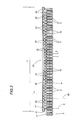
- figure 2 shows the portion of the cigar making machine as in figure 1, illustrated schematically in a plan view.
- Referring to figures 1 and 2 of the accompanying drawings, 1 denotes a portion of a machine for the manufacture of
cigars 2, comprising aframe 40, and avertical bulkhead 50 supported by the frame. - The
machine 1 also comprises a temporary storage anddistribution station 3 carried by thevertical bulkhead 50, at which thecigars 2 are fed singly and in succession from ahopper 4, forming part of thestation 3, onto a conveyor denoted 5. - The
conveyor 5 serves to transfer thecigars 2 in a given direction D1 and along a predetermined feed path P toward atreatment station 6 of conventional type, illustrated only in part. - The
conveyor 5 comprises abelt 7 looped around twopulleys 8 and 9 of which one only, denoted 9 in figure 1, is power driven and turns continuously. - The
pulleys 8 and 9 are carried by thevertical bulkhead 50 and rotatable aboutrespective axes 10 and 11 disposed normal to the viewing plane of figure 1, whilst thebelt 7 carries a plurality ofblocks 12 distributed uniformly at a predetermined pitch F along the outwardly directed surface of the loop. - The
blocks 12 are fashioned each with agroove 13 extending parallel to theaxes 10 and 11 of the pulleys and establishing arespective pocket 14 in which to accommodate arespective cigar 2, disposed with its longitudinal axis A extending parallel to theaforementioned axes 10 and 11 of rotation and transversely to the conveying direction D1. - The
belt 7 of theconveyor 5 affords anactive top branch 7a by which theblocks 12 are carried along the feed path P, and abottom branch 7b along which the blocks are returned toward the temporary storage anddistribution station 3. - The temporary storage and
distribution station 3, which is of conventional embodiment and therefore not described further, also comprises a plurality of substantiallyvertical channels 15 andrelative transfer mechanisms 16 by which thecigars 2 are directed singly and in ordered succession into thepockets 14 of theconveyor 5. - The
machine 1 further comprises abelt 17 looped around twopulleys - The
pulleys vertical bulkhead 50 and rotatable aboutrespective axes 20 and 21 disposed normal to the viewing plane of figure 1, whilst thebelt 17 carries a plurality ofheads 22 distributed uniformly at a predetermined pitch F along the outwardly directed surface of the loop. - The
heads 22 are provided each with arespective piercing needle 23 that extends in a direction D2 parallel to the longitudinal axis A of thesingle cigar 2. - The
belt 17 extends parallel to theconveyor 5 described above, running directly alongside through a set distance denoted T; the twobelts station 24 at which thecigars 2 are pierced. - The
needle heads 22 are advanced by thebelt 17 in such a way as to move synchronously with thebelt 7 of theconveyor 5 along the feed path P, each one travelling through the aforementioned distance T in alignment with arespective pocket 14 accommodating asingle cigar 2. - The
needle heads 22 are capable of movement in the aforementioned direction D2, toward and away from thepockets 14 accommodating thecigars 2, in such a way that theneedles 23 are made to engage thesingle cigars 2 and then disengage, according to a given law of motion. - Referring to figure 2, the
machine 1 comprises acam element 25 of which the profile is indicated by a phantom line, serving to generate the movement of theneedle heads 22. - In short, during the course of its passage along the feed path P, each
needle head 22 is caused to translate in the aforementioned direction D2, hence transverse to the selfsame path P, as a result of interacting with the profile of thecam element 25. Theheads 22 will engage the cam profile by way of conventional interface mechanisms not illustrated in the drawings. - As indicated in figure 1, the
treatment station 6 is disposed facing anexit end 26 of theconveyor 5 and presents a plurality of conventional wrapping and packaging devices of which one only, atransfer wheel 27, is illustrated. - Each
needle head 22 is equipped with adevice 28, located internally, by which therelative needle 23 can be heated and maintained at a temperature such as will ensure thecigar 2 is efficiently pierced. - The
needle heads 22 and therelative needles 23 together constitute means 60 by which to pierce thecigars 2. - In operation,
cigars 2 collecting internally of thehopper 4 will work their way down thevertical channels 15 and are then positioned by thetransfer mechanisms 16 in therespective pockets 14 afforded by theblocks 12 associated with thebelt 7 of theconveyor 5, arranged in an ordered succession. - The
belt 7 is set in motion by an actuator of familiar type, indicated schematically in figure 1 by a block denoted 29, in such a way as to advance thepockets 14 continuously along the feed path P followed by theactive branch 7a of theconveyor 5. - As the
cigars 2 enter thepiercing station 24, each occupying arespective pocket 14, each of theblocks 12 will be joined alongside by arelative needle head 22 carried and advanced by therelative belt 17, driven by an actuator likewise of familiar type indicated schematically in figure 1 by a block denoted 30. - In an alternative embodiment of the invention, not illustrated, the
belts - Each
block 12 proceeds along the feed path P for the entire set distance T aforementioned, advancing in alignment with theneedle head 22 alongside. - As discernible in figure 2, the
needle heads 22 are displaced as they advance along the feed path P and through the set distance T, moving transversely to the selfsame path P in the direction denoted D2, in such a manner that theneedles 23 are caused to engage thecorresponding cigars 2. - In other words, the
needle heads 22 are invested with movement in the aforementioned direction D2 toward and away from thecigars 2 occupying thepockets 14, to the end of causing theneedles 23 first to penetrate and then to withdraw from thecigars 2. - The movement of the
heads 22 in the transverse direction D2, within the distance T compassed by thepiercing station 24, is brought about according to the aforementioned law of motion imposed by the profile of thecam element 25. - The
needle heads 22 are afforded the necessary freedom of movement in the transverse direction D2, in relation to thebelt 17, by means of sliding devices such as glides, for example, conventional in embodiment and therefore not illustrated in the drawings. - The sliding devices in question combine with the
cam element 25 to constitute means, likewise not illustrated, by which movement is transmitted to theneedle heads 22. - Observing figure 2, it will be seen that in the course of advancing along the set distance T of the
piercing station 24, theneedle 23 of eachhead 22 is inserted gradually into anend portion 31 of arespective cigar 2, penetrating to a certain depth in a direction V concurrent with the longitudinal axis A of thecigar 2. - Penetrating thus into the
cigar 2, accordingly, theneedle 23 forms ahole 32 aligned substantially on the longitudinal axis A and, as a result of the thermal effect induced by theheating device 28 aforementioned, subjects the internal surface of thehole 32 to a heat-stretching action that has the effect of preventing theselfsame hole 32 from closing up after theneedle 23 is withdrawn. - As readily discernible in figure 2, the
needle 23 remains inside thehole 32 for a given conveying distance, and therefore for a certain interval of time, precisely to ensure that the heat-stretching action will be applied effectively to the internal surface of thehole 32. - On reaching the
aforementioned exit end 26 of theconveyor 5, thesingle needle head 22 assumes a limit position of maximum distance from the cigars, and more exactly, fully withdrawn from thesingle cigar 2 in which it has just pierced ahole 32. - Likewise at the
exit end 26 of theconveyor 5, thecigars 2 pierced with ahole 32 are taken up singly and in succession by thetransfer wheel 27 of thetreatment station 6 which, to reiterate, is illustrated only in part. - The
blocks 12 affording thepockets 14 occupied by thecigars 2 will present locating elements, not illustrated, each functioning as a reaction surface for therelative cigar 2 when pressure is applied during the piercing action of thehead 22, and serving to maintain the correct position of thecigar 2 in thepocket 14. - Advantageously, the profile of the
cam element 25 can be varied to the end of controlling the speed at which theneedle 23 penetrates thecigar 2, so as to optimize the piercing step not least with the different dimensional and/or constituent features of thecigar 2 in mind, and to avoid damaging the product. - In an alternative embodiment of the invention, not illustrated in the drawings, the
pockets 14 occupied by thecigars 2 are capable of movement toward and away from theneedle heads 22 in the direction D2 parallel to the longitudinal axis A of the cigar, in such a way that thecigars 2 are made to engage theneedles 23 and then to disengage, according to a given law of motion. In effect, this alternative solution is one in which theneedles 23 advance along the feed path P staying substantially motionless in the transverse direction D2, whilst it is thepockets 14 accommodating thecigars 2 that move in this same direction D2 while advancing along the feed path P. - In a further embodiment, not illustrated, the conveyor is embodied not as a
belt 7 but as a wheel carrying thepockets 14 occupied by thecigars 2. In this instance it is the surface of revolution of the wheel that establishes the feed path P along which thecigars 2 advance continuously. Likewise in this instance theheads 22 will be carried not by abelt 17 but by a wheel breasted axially with the wheel carrying thepockets 14. The two wheels rotate continuously, timed and synchronized one with another. - Finally, in yet another alternative solution, the
pockets 14 and theneedle heads 22 could both be carried by one continuously rotating wheel.
Claims (13)
- A method of conditioning cigars, comprising the steps of arranging the cigars (2) in an ordered succession on respective holder elements (14), advancing the cigars (2) with the holder elements (14) along a predetermined feed path (P), and piercing a hole (32) in at least one end (31) of each cigar (2), substantially parallel with a longitudinal axis (A) of the selfsame cigar (2), characterized in that the cigars (2) are caused to advance continuously along the predetermined feed path (P); and in that the step of piercing a hole (32) in each cigar (2) is accomplished during the continuous movement of the cigars (2) along the predetermined path (P) .
- A method as in claim 1, wherein the step of piercing a hole (32) in each cigar (2) is effected through the agency of piercing means (60) capable of movement along the predetermined feed path (P) synchronously with the cigars (2).
- A method as in claim 2, wherein the cigars (2) are pierced by piercing means (60) consisting in a plurality of needles (23) carried by respective needle heads (22).
- A method as in claim 2 or 3, comprising the further step of heating the piercing means (60).
- A machine for conditioning cigars, comprising conveyor means (5) by which the cigars (2) are advanced along a predetermined feed path (P); a distribution station (3) at which the cigars (2) are dispensed onto a plurality of holder elements (14) afforded by the conveyor means (5); also piercing means (60) operating in conjunction with the conveyor means (5) in such a way as to penetrate at least one respective end portion (31) presented by each of the cigars (2) advancing along the predetermined path (P), characterized in that the conveyor means (5) operate continuously so as to advance the cigars (2) continuously along the predetermined feed path (P) .
- A machine as in claim 5, wherein conveyor means (5) comprise a belt (7) looped around respective rotary transmission components (8, 9) and carrying the holder elements (14) occupied by the cigars (2), and presenting an active branch (7a) on which the selfsame cigars (2) are caused to advance along the predetermined feed path (P).
- A machine as in claim 5, wherein conveyor means (5) comprise a wheel carrying the holder elements (14) occupied by the cigars (2), which when set in rotation establishes the predetermined feed path.
- A machine as in claims 5 to 7, wherein piercing means (60) comprise a plurality of needles (23) carried by relative heads (22), each capable of movement synchronously with the holder elements (14) along the predetermined feed path (P) followed by the cigars (2), in such a manner that the respective needle (23) can pierce a cigar (2) occupying one of the holder elements (14) and advancing along the predetermined feed path (P).
- A machine as in claim 8, wherein the needle heads (22) are capable of movement toward and away from the cigars (2) occupying the holder elements (14) in a direction (D2) substantially concurrent with the longitudinal axes (A) of the cigars (2), in such a way that the needles (23) are made to engage with and then to disengage from the cigars (2) according to a given law of motion.
- A machine as in claim 9, comprising means of transmitting movement to the needle heads (22) such as will implement the given law of motion.
- A machine as in claim 10, wherein means of transmitting movement comprise a cam element (25) extending along the predetermined feed path (P), by which the needle heads (22) are engaged and invested with movement according to the given law of motion.
- A machine as claim 8, wherein the holder elements (14) occupied by the cigars (2) are capable of movement toward and away from the needle heads (22) in a direction (D2) substantially concurrent with the longitudinal axes (A) of the cigars (2), in such a way that the needles (23) are made to engage with and then to disengage from the cigars (2) according to a given law of motion.
- A machine as in claims 8 to 12, wherein each of the piercing means (60) comprises a device (28) serving to heat the relative needle (23).
Applications Claiming Priority (2)
| Application Number | Priority Date | Filing Date | Title |
|---|---|---|---|
| IT2001BO000469A ITBO20010469A1 (en) | 2001-07-24 | 2001-07-24 | METHOD FOR THE CONDITIONING OF CIGARS |
| ITBO20010469 | 2001-07-24 |
Publications (1)
| Publication Number | Publication Date |
|---|---|
| EP1279342A1 true EP1279342A1 (en) | 2003-01-29 |
Family
ID=11439514
Family Applications (1)
| Application Number | Title | Priority Date | Filing Date |
|---|---|---|---|
| EP02425472A Withdrawn EP1279342A1 (en) | 2001-07-24 | 2002-07-19 | A method of conditioning cigars |
Country Status (3)
| Country | Link |
|---|---|
| US (1) | US6732742B2 (en) |
| EP (1) | EP1279342A1 (en) |
| IT (1) | ITBO20010469A1 (en) |
Families Citing this family (1)
| Publication number | Priority date | Publication date | Assignee | Title |
|---|---|---|---|---|
| KR101758152B1 (en) * | 2010-10-22 | 2017-07-14 | 삼성전자주식회사 | Apparatus and method for handling network loss in wireless access system |
Citations (4)
| Publication number | Priority date | Publication date | Assignee | Title |
|---|---|---|---|---|
| US2800133A (en) * | 1955-08-18 | 1957-07-23 | Jno H Swisher & Son Inc | Cigar head puncher attachment |
| US3636958A (en) * | 1970-08-03 | 1972-01-25 | Jno H Swisher & Son Inc | Cigar handling apparatus |
| US4047535A (en) * | 1976-03-29 | 1977-09-13 | Peter Wimmer | Method of and apparatus for improving smoking properties of tobacco products |
| DE2614220A1 (en) * | 1976-04-02 | 1977-10-20 | Heinrich Grundmann | Cutting mechanism for cigarette making machine - has notched belt travelling in synchronism with conveyor past cutting tools |
Family Cites Families (1)
| Publication number | Priority date | Publication date | Assignee | Title |
|---|---|---|---|---|
| US3610254A (en) * | 1969-06-18 | 1971-10-05 | American Tobacco Co | Cigar-pressing method |
-
2001
- 2001-07-24 IT IT2001BO000469A patent/ITBO20010469A1/en unknown
-
2002
- 2002-07-17 US US10/196,279 patent/US6732742B2/en not_active Expired - Fee Related
- 2002-07-19 EP EP02425472A patent/EP1279342A1/en not_active Withdrawn
Patent Citations (4)
| Publication number | Priority date | Publication date | Assignee | Title |
|---|---|---|---|---|
| US2800133A (en) * | 1955-08-18 | 1957-07-23 | Jno H Swisher & Son Inc | Cigar head puncher attachment |
| US3636958A (en) * | 1970-08-03 | 1972-01-25 | Jno H Swisher & Son Inc | Cigar handling apparatus |
| US4047535A (en) * | 1976-03-29 | 1977-09-13 | Peter Wimmer | Method of and apparatus for improving smoking properties of tobacco products |
| DE2614220A1 (en) * | 1976-04-02 | 1977-10-20 | Heinrich Grundmann | Cutting mechanism for cigarette making machine - has notched belt travelling in synchronism with conveyor past cutting tools |
Also Published As
| Publication number | Publication date |
|---|---|
| ITBO20010469A1 (en) | 2003-01-24 |
| US20030019500A1 (en) | 2003-01-30 |
| ITBO20010469A0 (en) | 2001-07-24 |
| US6732742B2 (en) | 2004-05-11 |
Similar Documents
| Publication | Publication Date | Title |
|---|---|---|
| US2330361A (en) | Method of and apparatus for producing bags | |
| US4969308A (en) | Method of attaching a drinking straw to a pack and apparatus for carrying out the method | |
| US6585300B1 (en) | Apparatus for applying string to tampon pledgets | |
| US6654992B2 (en) | Method of applying string to tampon pledgets | |
| US4741145A (en) | Packing machines | |
| US4108299A (en) | Apparatus and method for delivering tampon sacks and inserter parts to an assembly turret | |
| EP1939092A2 (en) | Method and device for packaging small articles | |
| EP0875207A3 (en) | Stand alone swage method and apparatus | |
| US6732742B2 (en) | Method of conditioning cigars | |
| US4134502A (en) | Apparatus for forming groups made up by a plurality of side-by-side positioned piles of parallelepipedon shaped articles | |
| CA1093416A (en) | Method and apparatus for perforating an assembled filter used on a smoking product | |
| GB1573634A (en) | Cigarette packaging machine | |
| US3479787A (en) | Method and apparatus for packing blocks of cigarettes and the like | |
| US4319589A (en) | Method and apparatus for perforating rod-like articles | |
| US4216706A (en) | Manufacture of smoking articles | |
| US2504987A (en) | Pin setting machine and method | |
| US2331506A (en) | Apparatus for punching cigars | |
| US4208955A (en) | Container manufacturing apparatus and method | |
| JP2530191B2 (en) | Method for continuously processing and packaging an elongated product such as a pair of closely attached chopsticks, and apparatus for implementing this method | |
| US1999910A (en) | Manufacture of cigarettes | |
| US2267192A (en) | Cigar piercer and wrapper | |
| US3257883A (en) | Apparatus for making cigarettes | |
| US2984274A (en) | Pear peeling machine | |
| US2204980A (en) | High speed cigar machine | |
| US2253169A (en) | Head trimmer |
Legal Events
| Date | Code | Title | Description |
|---|---|---|---|
| PUAI | Public reference made under article 153(3) epc to a published international application that has entered the european phase |
Free format text: ORIGINAL CODE: 0009012 |
|
| AK | Designated contracting states |
Designated state(s): AT BE BG CH CY CZ DE DK EE ES FI FR GB GR IE IT LI LU MC NL PT SE SK TR |
|
| AX | Request for extension of the european patent |
Extension state: AL LT LV MK RO SI |
|
| 17P | Request for examination filed |
Effective date: 20030325 |
|
| AKX | Designation fees paid |
Designated state(s): AT BE BG CH CY CZ DE DK EE ES FI FR GB GR IE IT LI LU MC NL PT SE SK TR |
|
| STAA | Information on the status of an ep patent application or granted ep patent |
Free format text: STATUS: THE APPLICATION IS DEEMED TO BE WITHDRAWN |
|
| 18D | Application deemed to be withdrawn |
Effective date: 20050201 |