EP1278408A2 - Heat dissipation assembly - Google Patents
Heat dissipation assembly Download PDFInfo
- Publication number
- EP1278408A2 EP1278408A2 EP02254158A EP02254158A EP1278408A2 EP 1278408 A2 EP1278408 A2 EP 1278408A2 EP 02254158 A EP02254158 A EP 02254158A EP 02254158 A EP02254158 A EP 02254158A EP 1278408 A2 EP1278408 A2 EP 1278408A2
- Authority
- EP
- European Patent Office
- Prior art keywords
- heat dissipation
- dissipation device
- heat
- substrate
- base
- Prior art date
- Legal status (The legal status is an assumption and is not a legal conclusion. Google has not performed a legal analysis and makes no representation as to the accuracy of the status listed.)
- Withdrawn
Links
Images


Classifications
-
- H—ELECTRICITY
- H10—SEMICONDUCTOR DEVICES; ELECTRIC SOLID-STATE DEVICES NOT OTHERWISE PROVIDED FOR
- H10W—GENERIC PACKAGES, INTERCONNECTIONS, CONNECTORS OR OTHER CONSTRUCTIONAL DETAILS OF DEVICES COVERED BY CLASS H10
- H10W40/00—Arrangements for thermal protection or thermal control
- H10W40/70—Fillings or auxiliary members in containers or in encapsulations for thermal protection or control
- H10W40/73—Fillings or auxiliary members in containers or in encapsulations for thermal protection or control for cooling by change of state
-
- H—ELECTRICITY
- H10—SEMICONDUCTOR DEVICES; ELECTRIC SOLID-STATE DEVICES NOT OTHERWISE PROVIDED FOR
- H10W—GENERIC PACKAGES, INTERCONNECTIONS, CONNECTORS OR OTHER CONSTRUCTIONAL DETAILS OF DEVICES COVERED BY CLASS H10
- H10W40/00—Arrangements for thermal protection or thermal control
- H10W40/60—Securing means for detachable heating or cooling arrangements, e.g. clamps
- H10W40/611—Bolts or screws
Definitions
- This invention relates generally to improving the heat dissipation of components assembled on a substrate, and preferably to providing a thermally reliable attachment of a heat dissipation device to a plurality of electrical components on a substrate, while maintaining vibration isolation between the heat dissipation device and the electrical components.
- one or more electrical components e.g., central processing unit chips, and other integrated circuit chips operating at very high frequencies individually dissipate a considerable amount of heat during operation. If the heat dissipation mechanism for cooling such a high power dissipation component is not adequate, then the temperature of the high power dissipation component will quickly rise to a temperature that results in either temporary or permanent operational failure of that component, and typically failure of the entire data processing system dependent on that component.
- the industry standard package styles for high power dissipation electrical components frequently consist of ceramic body pin grid arrays (PGAs) for through-hole substrates, or ceramic surface mount equivalents (e.g., land grid array components, ball grid array components, and so forth) for surface mount substrates.
- the body of an electrical component is frequently thermally coupled to a heat dissipation device (e.g., a heat sink, a heat-pipe, a fluid cooling system, a cooling fan, or other equivalent devices).
- a heat dissipation device e.g., a heat sink, a heat-pipe, a fluid cooling system, a cooling fan, or other equivalent devices.
- vapour chamber A special type of heat-pipe known as a vapour chamber is sometimes used when a large amount of heat dissipation capability is required for a processor chip or other high power dissipation component.
- a vapour chamber is a relatively expensive single point-of-failure for an electrical component. The failure of a vapour chamber is so catastrophic for an electrical component that a considerable amount of money is spent in fabricating reliable vapour chambers. However, a serious reliability problem has emerged with vapour chambers, since there is no redundant heat conduction path to provide substitute heat dissipation if the vapour chamber fails to operate.
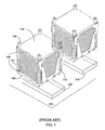
- FIG. 1 illustrates two conventional heat dissipation devices attached to two components 218, 219 that are attached to a substrate 220.
- Each heat dissipation device comprises a vertically stacked plurality of rectangular heat dissipation fins 108, which are enclosed by a hardware structure 114.
- the hardware structure 114 includes two or more walls 118 (one is shown), and the hardware structure is typically fabricated of the same metal as the heat dissipation device.
- the hardware structure 114 holds a plurality of screws 120 (typically four long screws are used) and screw springs 111 to attach a base 106 of the heat dissipation device to the substrate 220.
- the present invention seeks to provide improved heat dissipation for electrical components.
- the preferred embodiments can provide an attachment to thermally connect a heat dissipation device to multiple components while maintaining vibration isolation between the heat dissipation device and the multiple components. They can also provide a heat dissipation device that can use supply redundant, fault-tolerant heat dissipation, instead of using a single vapour chamber for heat dissipation.
- the preferred system provides an attachment to thermally connect a heat dissipation device to multiple components while maintaining vibration isolation between the heat dissipation device and the multiple components. It also provides a heat dissipation device that can supply redundant, fault-tolerant heat dissipation, instead of using a single vapour chamber for heat dissipation.
- a preferred method of assembling a plurality of components on a substrate to a heat dissipation device includes attaching a channelled base to the heat dissipation device; thermally attaching one or more heat-pipes to the channelled base; placing the heat dissipation device and the channelled base on the plurality of components on the substrate; and physically attaching the heat dissipation device to the substrate, wherein the heat dissipation device channelled base includes one or more heat-pipes thermally coupled to a component of the plurality of components.
- Another embodiment assembles a plurality of components on a substrate to a heat dissipation device containing one or more heat-pipes.
- the method includes attaching a base to the heat dissipation device; thermally attaching one or more heat-pipes to the base; placing the base of the heat dissipation device on the plurality of components on the substrate; and attaching the base of the heat dissipation device to the substrate, wherein the heat dissipation device base includes one or more heat-pipes to substantially attain an isothermal heat dissipation device base.
- a preferred assembled substrate with a plurality of electrical components attached to a common heat dissipation device includes a substrate; a plurality of electrical components attached to the substrate; a heat dissipation device attached to the plurality of electrical components, wherein the heat dissipation device includes one or more heat-pipes inside the heat dissipation device.
- the described embodiments provide a multiple component heat dissipation device that uses a lower cost, fault-tolerant group of heat-pipes. This can increase the amount of fin area of the heat dissipation device while allowing a shorter profile fin area for improved airflow or higher component packing density. While the discussion below is directed to an application to processor chips assembled on a substrate (e.g., a PCB), the teachings herein can also be applied to any type of high power dissipation electrical component assembled on any type of substrate (e.g., a multi-chip module, or another substrate upon which electrical components can be assembled).
- a substrate e.g., a PCB
- the teachings herein can also be applied to any type of high power dissipation electrical component assembled on any type of substrate (e.g., a multi-chip module, or another substrate upon which electrical components can be assembled).
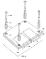
- FIG. 2 illustrates an assembly of a heat dissipation device (e.g., a heat-sink) according to one embodiment of the present invention.
- the heat dissipation device assembly includes several heat dissipation fins 206 and a base 208, sitting on two components 218 and 219 attached to a substrate 220.
- the heat dissipation fins 206 are stacked on spacers (not shown) or fin flanges (not shown) to maintain a uniform stacking separation.
- the heat dissipation device assembly also includes four short screws 210, four springs 211, and four washers 212.
- the heat dissipation fins have four holes 216 that are aligned to form vertical wells to receive the four short screws 210, four springs 211, and four washers 212 for attachment to the substrate 220.
- FIG. 3 illustrates a bottom view of the base 208 of the heat dissipation device assembly shown in FIG. 2, according to one embodiment of the present invention.
- the heat dissipation device base 208 has three heat-pipe channels 302, 306 and 310, which contain three heat-pipes 304, 308, and 312, respectively.
- Other embodiments of the invention could use a smaller number (e.g., two) of heat-pipe channels, or use a larger number (e.g., four to over a dozen) heat-pipe channels in the base.
- These channels could be machined grooves or moulded grooves with various cross-sections (e.g., semicircular grooves, rectangular grooves, triangular grooves, and so forth).
- these channels can be holes, where the heat-pipes can be inserted into holes running all or part of the length of the base, and the holes are drilled (e.g., gun-drilled) or cold-forged.
- the heat-pipes can be installed using either an adhesive (e.g., an epoxy) or a solder.
- a heat-pipe can be expanded into a hole.
- each channel can accommodate one or more heat-pipes.
- the heat-pipes are preferably standard straight sintered copper heat-pipes, but other types of heat-pipes (e.g., screen wick heat-pipes) can be used in alternative embodiments of the invention.
- the heat-pipe diameters are preferably 0.63 centimetres (0.25 inches), but the diameters can be either smaller or larger in alternate embodiments of the invention.
- the heat-pipes are preferably embedded and partially exposed on the heat dissipation device base, but in alternative embodiments of the invention the heat-pipes can be completely enclosed in the heat dissipation device base.
- the heat dissipation device base thickness preferably ranges in thickness from approximately 1.0 centimetre (0.4 inches) to 0.5 centimetre (0.2 inches), but in alternative embodiments of the invention the heat dissipation device base can be thinner or thicker as needed. In alternative embodiments, the heat dissipation device base can itself be used as a platform for attached electrical components (e.g., ICs, resistors, capacitors, inductors, and related electrical components).
- electrical components e.g., ICs, resistors, capacitors, inductors, and related electrical components.
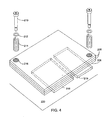
- FIG. 4 illustrates an assembly of a heat dissipation device (e.g., a heat-sink) according to another embodiment of the invention.
- the heat dissipation device assembly includes several heat dissipation fins 206 and a base 208, sitting on two components 218 and 219 attached to a substrate 220.
- the heat dissipation fins 206 can be stacked on spacers (not shown) or fin flanges (not shown) to maintain a uniform stacking separation.
- the heat dissipation device assembly also includes two short screws 210, two springs 211, and two washers 212.
- the heat dissipation fins have two holes 216 that are aligned to form vertical wells to receive the two short screws 210, two springs 211, and two washers 212 for attachment to the substrate 220.
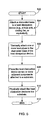
- FIG. 5 shows a flow chart for a method to assemble a heat dissipation device to a plurality of components in accordance with an embodiment of the present invention.
- the method starts in operation 502, and is followed by operation 504.
- a heat dissipation device e.g., a heat-pipe, heat-sink, fluid cooling device, cooling fan, or an equivalent.
- two or more heat-pipes are thermally attached to the channelled base of the heat dissipation device.
- operation 508 is next.
- the heat dissipation device is placed on the two or more components.
- the heat dissipation device is physically attached to the substrate, by screws, bolts, solder, or by an equivalent attachment method.
- ICs or passive components e.g., capacitors, resistors, and inductors
- Operation 512 is the end of the method.
- FIG. 6 shows another flow chart for a method to assemble a heat dissipation device to a plurality of components in accordance with another embodiment of the present invention.
- the method starts in operation 602, and is followed by operation 604.
- a heat dissipation device e.g., a heat-pipe, heat-sink, fluid cooling device, cooling fan, or an equivalent.
- two or more heat-pipes are attached to the channelled base of the heat dissipation device.
- operation 608 is next.
- two or more heat pipes are attached to two or more components attached to a substrate.
- the base of the heat dissipation device is placed on the two or more components.
- the heat dissipation device is physically attached to the substrate, by screws, bolts, solder, or by an equivalent attachment method.
- ICs or passive components e.g., capacitors, resistors, and inductors
- Operation 614 is the end of the method.
- inventions discussed above used examples of electrical components. However, alternative embodiments can be applied to other heat generating components (e.g., engines, generators, or other heat generating devices). Additionally, various embodiments that are applied to electrical component can be applied to PCBs using through-hole technology or surface mount technology, or other types of electrical component substrates (e.g., multi-chip modules and flexible substrates).
Landscapes
- Cooling Or The Like Of Electrical Apparatus (AREA)
- Cooling Or The Like Of Semiconductors Or Solid State Devices (AREA)
Abstract
Description
Claims (10)
- A method of assembling a plurality of components (218, 219) on a substrate (220) to a heat dissipation device (206), including the steps of:attaching a channelled base (208) to said heat dissipation device (206);thermally attaching one or more heat-pipes (304, 308, 312) to said channelled base (208);placing said heat dissipation device (206) and said channelled base (208) on said plurality of components (218, 219) on said substrate (220); andphysically attaching said heat dissipation device (206) to said substrate (220), wherein said heat dissipation device (206) channelled base (208) includes one or more heat-pipes (304, 308, and 312) thermally coupled to a component of said plurality of components (218, 219).
- A method as in claim 1, wherein said one or more heat-pipes (304, 308, 312) maintain said heat dissipation device base (208) at substantially an isothermal condition.
- A method as in claim 1 or 2, wherein said substrate (220) is a printed circuit board, a multi-chip module or a flexible substrate.
- A method as in claim 1, 2 or 3, wherein thermally attaching one or more heat-pipes (304, 308, 312) to said channelled base (208) is followed by thermally attaching said channelled base (208) of said heat dissipation device (206) to said plurality of components (218, 219).
- A method of assembling a plurality of components (218, 219) on a substrate (220) to a heat dissipation device (206) containing one or more heat-pipes (304, 308, 312), including the steps of:attaching a base (208) to said heat dissipation device (206);thermally attaching one or more heat-pipes (304, 308, 312) to said base (208);placing said base (208) of said heat dissipation device (206) on said plurality of components (218, 219) on said substrate (220); andattaching said base (208) of said heat dissipation device (206) to said substrate (220), wherein said heat dissipation device (206) base (208) includes one or more heat-pipes (304, 308, and 312) to substantially attain an isothermal heat dissipation device (206) base (208).
- A method as in claim 5, wherein said base (208) includes a plurality of channels (302, 306, and 310) to hold said one or more heat-pipes (304, 308, and 312).
- A method as in claim 5 or 6, wherein thermally coupling said one or more heat-pipes (304, 308, and 312) in said base (208) to said plurality of components (218, 219) precedes attaching said base (208) of said heat dissipation device (206) to said substrate (220).
- An assembled substrate with a plurality of electrical components (218, 219) attached to a common heat dissipation device (206), including:a substrate (220);a plurality of electrical components (218, 219) attached to said substrate (220);a heat dissipation device (206) attached to said plurality of electrical components (218, 219), wherein said heat dissipation device (206) includes one or more heat-pipes (304, 308, and 312) inside said heat dissipation device (206).
- An assembled substrate as in claim 8, wherein said heat dissipation device (206) is attached directly to said substrate (220).
- An assembled substrate as in claim 8 or 9, wherein one or more electrical components (218, 219) are attached to said heat dissipation device (206) base (208), and two or more electrical components (218, 219) are attached to said substrate (220).
Applications Claiming Priority (2)
| Application Number | Priority Date | Filing Date | Title |
|---|---|---|---|
| US909512 | 1986-09-19 | ||
| US09/909,512 US6667885B2 (en) | 2001-07-20 | 2001-07-20 | Attachment of a single heat dissipation device to multiple components with vibration isolation |
Publications (2)
| Publication Number | Publication Date |
|---|---|
| EP1278408A2 true EP1278408A2 (en) | 2003-01-22 |
| EP1278408A3 EP1278408A3 (en) | 2004-05-12 |
Family
ID=25427352
Family Applications (1)
| Application Number | Title | Priority Date | Filing Date |
|---|---|---|---|
| EP02254158A Withdrawn EP1278408A3 (en) | 2001-07-20 | 2002-06-14 | Heat dissipation assembly |
Country Status (3)
| Country | Link |
|---|---|
| US (1) | US6667885B2 (en) |
| EP (1) | EP1278408A3 (en) |
| JP (1) | JP2003115569A (en) |
Families Citing this family (20)
| Publication number | Priority date | Publication date | Assignee | Title |
|---|---|---|---|---|
| US6924437B1 (en) | 2003-04-10 | 2005-08-02 | Cisco Technology, Inc. | Techniques for coupling an object to a circuit board using a surface mount coupling device |
| US7184265B2 (en) * | 2003-05-29 | 2007-02-27 | Lg Electronics Inc. | Cooling system for a portable computer |
| US7188484B2 (en) | 2003-06-09 | 2007-03-13 | Lg Electronics Inc. | Heat dissipating structure for mobile device |
| US6982877B2 (en) * | 2004-02-20 | 2006-01-03 | Hewlett-Packard Development Company, L.P. | Heat sink having compliant interface to span multiple components |
| US20050274487A1 (en) * | 2004-05-27 | 2005-12-15 | International Business Machines Corporation | Method and apparatus for reducing thermal resistance in a vertical heat sink assembly |
| CN2713636Y (en) * | 2004-06-11 | 2005-07-27 | 鸿富锦精密工业(深圳)有限公司 | Locking device for radiator |
| US7239516B2 (en) * | 2004-09-10 | 2007-07-03 | International Business Machines Corporation | Flexure plate for maintaining contact between a cooling plate/heat sink and a microchip |
| US7117929B2 (en) * | 2004-10-27 | 2006-10-10 | Hewlett-Packard Development Company, Lp. | Heat sink |
| US20060109631A1 (en) * | 2004-11-02 | 2006-05-25 | Data Device Corporation | Method and apparatus for connecting circuit cards employing a cooling technique to achieve desired temperature thresholds and card alignment |
| US7321493B2 (en) * | 2004-12-01 | 2008-01-22 | Cisco Technology, Inc. | Techniques for attaching a heatsink to a circuit board using anchors which install from an underside of the circuit board |
| US7324344B2 (en) * | 2004-12-01 | 2008-01-29 | Cisco Technology, Inc. | Techniques for attaching a heatsink to a circuit board using anchors which install from an underside of the circuit board |
| WO2006112027A1 (en) * | 2005-04-15 | 2006-10-26 | Fujitsu Limited | Heat sink, circuit board and electronic device |
| US20060232928A1 (en) * | 2005-04-19 | 2006-10-19 | Vinson Wade D | Heat sink for multiple components |
| US7310226B2 (en) * | 2005-11-22 | 2007-12-18 | Super Micro Computer, Inc. | Modularized redundant heat sink for dissipating heat generated from chips |
| US7310232B2 (en) * | 2005-12-30 | 2007-12-18 | Igor Victorovich Touzov | Multi-surface heat sink film |
| US7609522B2 (en) * | 2006-12-01 | 2009-10-27 | Fu Zhun Precision Industry (Shen Zhen) Co., Ltd. | Heat sink assembly |
| CN101408301B (en) * | 2007-10-10 | 2012-09-19 | 富准精密工业(深圳)有限公司 | LED light fitting with heat radiating device |
| JP5744699B2 (en) * | 2011-10-19 | 2015-07-08 | 奇▲こう▼科技股▲ふん▼有限公司 | Heat dissipation device |
| CN103096678B (en) * | 2011-10-27 | 2017-09-15 | 全亿大科技(佛山)有限公司 | Heat abstractor |
| US10045464B1 (en) * | 2017-03-31 | 2018-08-07 | International Business Machines Corporation | Heat pipe and vapor chamber heat dissipation |
Family Cites Families (15)
| Publication number | Priority date | Publication date | Assignee | Title |
|---|---|---|---|---|
| JPH0563385A (en) * | 1991-08-30 | 1993-03-12 | Hitachi Ltd | Electronic apparatus and computer provided with heat pipe |
| JPH0629683A (en) * | 1992-03-31 | 1994-02-04 | Furukawa Electric Co Ltd:The | Heat pipe type heat dissipation unit for electronic devices |
| US5549155A (en) * | 1995-04-18 | 1996-08-27 | Thermacore, Inc. | Integrated circuit cooling apparatus |
| JP3268734B2 (en) * | 1996-11-15 | 2002-03-25 | 古河電気工業株式会社 | Method of manufacturing electronic device heat radiation unit using heat pipe |
| US6167948B1 (en) * | 1996-11-18 | 2001-01-02 | Novel Concepts, Inc. | Thin, planar heat spreader |
| DE19805930A1 (en) * | 1997-02-13 | 1998-08-20 | Furukawa Electric Co Ltd | Cooling arrangement for electrical component with heat convection line |
| US6424528B1 (en) * | 1997-06-20 | 2002-07-23 | Sun Microsystems, Inc. | Heatsink with embedded heat pipe for thermal management of CPU |
| US6163073A (en) * | 1998-04-17 | 2000-12-19 | International Business Machines Corporation | Integrated heatsink and heatpipe |
| US6021044A (en) * | 1998-08-13 | 2000-02-01 | Data General Corporation | Heatsink assembly |
| US6061235A (en) * | 1998-11-18 | 2000-05-09 | Hewlett-Packard Company | Method and apparatus for a modular integrated apparatus for heat dissipation, processor integration, electrical interface, and electromagnetic interference management |
| US6137683A (en) * | 1999-10-01 | 2000-10-24 | Compal Electronics, Inc. | Heat-dissipating device for an electronic component |
| JP3852253B2 (en) * | 1999-10-21 | 2006-11-29 | 富士通株式会社 | Electronic component cooling device and electronic equipment |
| US6397941B1 (en) * | 1999-12-01 | 2002-06-04 | Cool Options, Inc. | Net-shape molded heat exchanger |
| US6212074B1 (en) * | 2000-01-31 | 2001-04-03 | Sun Microsystems, Inc. | Apparatus for dissipating heat from a circuit board having a multilevel surface |
| US6449162B1 (en) * | 2001-06-07 | 2002-09-10 | International Business Machines Corporation | Removable land grid array cooling solution |
-
2001
- 2001-07-20 US US09/909,512 patent/US6667885B2/en not_active Expired - Lifetime
-
2002
- 2002-06-14 EP EP02254158A patent/EP1278408A3/en not_active Withdrawn
- 2002-07-19 JP JP2002210492A patent/JP2003115569A/en not_active Withdrawn
Also Published As
| Publication number | Publication date |
|---|---|
| EP1278408A3 (en) | 2004-05-12 |
| JP2003115569A (en) | 2003-04-18 |
| US20030016500A1 (en) | 2003-01-23 |
| US6667885B2 (en) | 2003-12-23 |
Similar Documents
| Publication | Publication Date | Title |
|---|---|---|
| US6667885B2 (en) | Attachment of a single heat dissipation device to multiple components with vibration isolation | |
| US6807061B1 (en) | Stack up assembly | |
| US6212074B1 (en) | Apparatus for dissipating heat from a circuit board having a multilevel surface | |
| US5969949A (en) | Interfitting heat sink and heat spreader slug | |
| JP3445936B2 (en) | Semiconductor package lid with heat pipe | |
| US5754401A (en) | Pressure compliantly protected heatsink for an electronic device | |
| TWI378612B (en) | Modification of connections between a die package and a system board | |
| US5615086A (en) | Apparatus for cooling a plurality of electrical components mounted on a printed circuit board | |
| US7388746B2 (en) | Heatsink assembly | |
| US9807905B2 (en) | Adapter cooling apparatus and method for modular computing devices | |
| US6404632B1 (en) | Mechanical configuration for retaining inboard mounting hardware on finned heat dissipating devices | |
| US5737187A (en) | Apparatus, method and system for thermal management of an unpackaged semiconductor device | |
| JPH04330745A (en) | Flexible interconnection module | |
| JP2000156554A (en) | Module type integrated device | |
| US20040124517A1 (en) | Structural reinforcement for electronic substrate | |
| US6700195B1 (en) | Electronic assembly for removing heat from a flip chip | |
| US20030160319A1 (en) | Solid assembly of flip-chip package attached to heat removal device and method of manufacturing same | |
| US6377463B1 (en) | Retention module for processor and chipset thermal solutions | |
| US10622279B1 (en) | Heatsink mounting system with overhang damping | |
| US7360586B2 (en) | Wrap around heat sink apparatus and method | |
| US6580613B2 (en) | Solder-free PCB assembly | |
| US20100128443A1 (en) | Heat dissipating module | |
| US6541710B1 (en) | Method and apparatus of supporting circuit component having a solder column array using interspersed rigid columns | |
| EP3996480B1 (en) | Conductive thermal management architecture for electronic devices | |
| US20020189089A1 (en) | Mounting electrical devices to circuit boards |
Legal Events
| Date | Code | Title | Description |
|---|---|---|---|
| PUAI | Public reference made under article 153(3) epc to a published international application that has entered the european phase |
Free format text: ORIGINAL CODE: 0009012 |
|
| AK | Designated contracting states |
Kind code of ref document: A2 Designated state(s): AT BE CH CY DE DK ES FI FR GB GR IE IT LI LU MC NL PT SE TR |
|
| AX | Request for extension of the european patent |
Free format text: AL;LT;LV;MK;RO;SI |
|
| PUAL | Search report despatched |
Free format text: ORIGINAL CODE: 0009013 |
|
| AK | Designated contracting states |
Kind code of ref document: A3 Designated state(s): AT BE CH CY DE DK ES FI FR GB GR IE IT LI LU MC NL PT SE TR |
|
| AX | Request for extension of the european patent |
Extension state: AL LT LV MK RO SI |
|
| RIC1 | Information provided on ipc code assigned before grant |
Ipc: 7H 01L 23/427 B Ipc: 7H 05K 7/20 A |
|
| 17P | Request for examination filed |
Effective date: 20040705 |
|
| AKX | Designation fees paid |
Designated state(s): DE FR GB |
|
| 17Q | First examination report despatched |
Effective date: 20060707 |
|
| 17Q | First examination report despatched |
Effective date: 20060707 |
|
| STAA | Information on the status of an ep patent application or granted ep patent |
Free format text: STATUS: THE APPLICATION IS DEEMED TO BE WITHDRAWN |
|
| 18D | Application deemed to be withdrawn |
Effective date: 20070703 |