EP1278406B1 - Apparatus for making multi-layered printed circuits - Google Patents
Apparatus for making multi-layered printed circuits Download PDFInfo
- Publication number
- EP1278406B1 EP1278406B1 EP01830478A EP01830478A EP1278406B1 EP 1278406 B1 EP1278406 B1 EP 1278406B1 EP 01830478 A EP01830478 A EP 01830478A EP 01830478 A EP01830478 A EP 01830478A EP 1278406 B1 EP1278406 B1 EP 1278406B1
- Authority
- EP
- European Patent Office
- Prior art keywords
- station
- plate
- storing
- drawer
- assembling station
- Prior art date
- Legal status (The legal status is an assumption and is not a legal conclusion. Google has not performed a legal analysis and makes no representation as to the accuracy of the status listed.)
- Expired - Lifetime
Links
- 230000003287 optical effect Effects 0.000 claims description 15
- 238000007789 sealing Methods 0.000 claims description 3
- 238000004891 communication Methods 0.000 claims description 2
- 238000004519 manufacturing process Methods 0.000 description 5
- 230000009467 reduction Effects 0.000 description 3
- 230000008859 change Effects 0.000 description 2
- 238000010276 construction Methods 0.000 description 2
- 230000009471 action Effects 0.000 description 1
- 230000002411 adverse Effects 0.000 description 1
- 239000007767 bonding agent Substances 0.000 description 1
- 239000003795 chemical substances by application Substances 0.000 description 1
- 230000009977 dual effect Effects 0.000 description 1
- 230000000694 effects Effects 0.000 description 1
- 239000003292 glue Substances 0.000 description 1
- 238000010438 heat treatment Methods 0.000 description 1
- 230000007246 mechanism Effects 0.000 description 1
- 239000000155 melt Substances 0.000 description 1
- 238000012986 modification Methods 0.000 description 1
- 230000004048 modification Effects 0.000 description 1
- 238000007711 solidification Methods 0.000 description 1
- 230000008023 solidification Effects 0.000 description 1
Images



Classifications
-
- H—ELECTRICITY
- H05—ELECTRIC TECHNIQUES NOT OTHERWISE PROVIDED FOR
- H05K—PRINTED CIRCUITS; CASINGS OR CONSTRUCTIONAL DETAILS OF ELECTRIC APPARATUS; MANUFACTURE OF ASSEMBLAGES OF ELECTRICAL COMPONENTS
- H05K3/00—Apparatus or processes for manufacturing printed circuits
- H05K3/46—Manufacturing multilayer circuits
- H05K3/4611—Manufacturing multilayer circuits by laminating two or more circuit boards
Definitions
- the present invention relates to an apparatus for making cards for multi-layered printed circuits, of the type comprising the features set forth in the preamble of claim 1.
- the present invention addresses to the electronic sector and in particular to the production of printed circuits normally used in computers, telephones or electronic apparatus of various kinds. More specifically, the apparatus in accordance with the invention lends itself to be used in the step of assembling the different layers forming a multi-layered card.
- outer layers on which the respective conductive paths are disposed, must be superposed and joined to form a finished card.
- An insulating film, called “pre-peg” and also performing the function of bonding agent or glue is interposed between a conductive layer and the next one.
- automatic apparatus are used that are adapted to individually pick up the conductive layers and insulating films and lay them down in an alternate sequence in an assembling station for alignment and subsequent junction of same.
- the conductive and insulating layers are piled up in adjacent containers, one type for each container, to enable them to be reached and picked up by appropriate grip members.
- Independent grip members running on appropriate rails, usually one for the conductive layers and one for the insulating layers, carry the layers from the storing regions to the assembling station.
- the Applicant has found that the apparatus of the above described type can be improved from different points of view, in particular as regards construction simplification, reduction in bulkiness and increase in the production speed, which will bring about a consequent reduction in costs.
- the above described known apparatus do not allow replacement of the typology of card being worked without stopping production over a very long period of time, so as to change all stacks of all conductive and insulating layers and carry out the necessary set-up operations of the different operating members present in the apparatus.
- an apparatus for making cards for multi-layered printed circuits in accordance with the present invention has been generally identified by reference numeral 1.
- Apparatus 1 comprises an assembling station 2 in which at least two conductive layers and one insulating layer are superposed on each other in an alternated sequence and joined to form a multi-layered card.
- the assembling station 2 is preferably made up of a support structure 3 on which an alignment table 4 extending in a horizontal plane is installed.
- the alignment table 4 has a dual function, i.e. that of supporting the card during assembling and of aligning the already joined conductive layers with each conductive layer added thereto.
- the assembling station 2 further comprises appropriate movement means 5 to move the table 4 relative to the support structure 3.
- said means 5 enables traversing of table 4 along two directions X, Y that are mutually orthogonal and parallel to the table 4 itself, as well as rotation of same relative to a vertical axis Z.
- table 4 is of a rectangular shape and the two traverse directions X, Y are parallel to the sides of same.
- the vertical rotation axis Z is placed close to one of the minor sides and at a symmetry axis 6 lying in the extension plane of table 4.
- table 4 is provided with a plurality of holes 7 communicating with a cavity 8 maintained under vacuum.
- the vacuum in cavity 8 generates a sucking effect ensuring adhesion of the first conductive layer to the alignment table 4.
- An optical position-detecting device 10 is disposed above table 4, being supported by a first frame 9 integral with the support structure 3.
- Such a device comprises two aligned optical detectors 10a, 10b at the symmetry axis 6 of table 4.
- a first optical detector 10a is fastened to the first frame 9 and lies close to the rotation axis Z of table 4, whereas a second optical detector 10b is movable in a direction parallel to table 4 along a track 11 mounted on the first frame 9.
- the assembling station 2 further comprises a plurality of welders mounted on a second frame 13.
- welders 12 are divided into two groups 12a, 12b symmetrically arranged at the sides of the optical detectors.
- welders 12 of each group 12a, 12b are aligned along a bar 14a, 14b parallel to the symmetry axis 6 of table 4 and movable, on appropriate rails 15 mounted to the second frame 13, between the edges of table 4 and the symmetry axis 6 of the table itself.
- Each individual welder 12 is, in addition, movable in a vertical direction between a first non-operating position, in which it is spaced apart from table 4, and an operating position in which it is close to said table 4 so that it can weld two superposed conductive layers together.
- Apparatus 1 in accordance with the invention further comprises a first storing station 16a to store the conductive layers, before use, and a second storing station 16b to store the insulating layers before use and lay down the multi-layered cards, once assembled.
- Each storing station 16a, 16b comprises a holding frame 17, mounted on support wheels 18, in which a plurality of mutually superposed drawers 19 are slidably inserted.
- Each drawer 19 is movable between a first position in which it is inserted in frame 17 and is piled up on the others, and a second position in which it is pulled out of frame 17 to enable either picking up of a conductive or insulating layer or deposit of a finished card.
- Each drawer 19 is provided with positioning means 20 enabling conductive layers, insulating layers or finished cards of different sizes to be kept at a predetermined position.
- said positioning means 20 comprises at least three abutment elements 21 movable in respective slide guides 22 formed in the rest surface 23 of drawer 19.
- the slide guides 22 are disposed symmetrically of a median axis 24 exhibited by each drawer 19 so that layers of different formats to be assembled can be always blocked at the centre line of the drawer 19 itself.
- the storing stations further comprise appropriate means for automatic movement of drawers 19, not shown.
- the present apparatus 1 also comprises a first grip member 25a, a second grip member 25b and actuating means 26 for said grip members 25a, 25b, to pick up and transfer the layers and finished cards.
- the first grip member 25a is movable in a horizontal direction between the first storing station 16a and the assembling station 2, to pick up a conductive layer and transfer it to the assembling station 2.
- the second grip member 25b is movable in a horizontal direction between the assembling station 2 and the second storing station 16b, to bring a finished card from the assembling station 2 to the second storing station 16b and, vice versa, to pick up an insulating layer and take it to the assembling station 2.
- the actuating means 26 rigidly connects the first grip member 25a to second grip member 25b in their horizontal movement. Therefore, while the first grip member 25a moves from the first storing station 16a to the assembling station 2, the second grip member 25b moves from the assembling station 2 to the second storing station 16b.
- the actuating means 26 comprises a rotating support structure 27 on which the two grip members 25a, 25b are mounted.
- Structure 27 rotates around its own vertical axis 28 through an arc of a circle of 120°, therefore the grip members 25a, 25b too are constrained to rotate together following the same arc of a circle.
- the grip members 25a, 25b are slidably mounted on structure 27 through respective vertical guides 29a, 29b.
- the storing stations 16, 16b and assembling station 2 are circumferentially distributed around the vertical axis 28 of the rotating support structure 27 and mutually spaced apart by an angle of 120°, so that they can be reached by the grip members 25a, 25b through mere angular-rotation movements around the same vertical axis 26.
- each of the two grip members 25a, 25b is made up of a horizontal sucking plate 30a, 30b of substantially rectangular shape.
- Each plate 30a, 30b comprises an upper wall 31, a lower wall 32, and at least one side wall 33 that altogether bound a chamber 34.
- the lower wall 32 has a plurality of holes 35 for communication between chamber 34 and the surrounding atmosphere.
- the maximum height that can be reached by plates 30a, 30b is slightly less than the height of the alignment table 4.
- Each of the plates 30a, 30b when placed close to the assembling station 2 is vertically aligned with the table itself, so that table 4 and plates 30a, 30b are superposed and form a narrow gap between them.
- the two plates 30a, 30b when placed at the respective storing stations 16a, 16b, are vertically aligned with each drawer 19 jutting out of from the containment frame 17.
- each drawer 19 is approached from top by the respective plate 30a, 30b so that the sucking lower wall 32 pierced with holes can get into contact with the upper layer in the drawer 19 itself.
- each plate 30a, 30b substantially has the same sizes as the rest surface 23 of each drawer 19.
- the upper 32 and lower 32 walls of each sucking plate 30a, 30b have a plurality of passages 36 through the plate 30a, 30b itself that are distributed at least along two mutually orthogonal directions to allow access to the tools present in the assembling station 2.
- passages 36 are defined by a plurality of openings 37 bounded by lateral sealing walls 33a disposed between the upper wall 31 and lower wall 32 at the edges of said openings 37.
- each plate 30a, 30b is provided with a series of first openings 38 through which welders 12 can pass.
- the series of first openings 38 is divided into two groups 38a, 38b of five openings disposed along two mutually opposite sides of the sucking plate 30a, 30b.
- said first openings 38 are of elongated rectangular shape and extend perpendicularly of the major sides of plate 30a, 30b towards a symmetry axis 39 exhibited by the plate 30a, 30b itself.
- each plate 30a, 30b is provided with a series of second openings 40 disposed on the symmetry axis 39 of said plates 30a, 30b.
- the second openings 40 are disposed along the action line of the optical detectors 10a, 10b.
- each sucking plate 30a, 30b has a series of third openings 41 in which the abutment elements 21 of drawers 19 can be inserted.
- the third openings 41 are three in number and are of elongated shape.
- a first one 41a of the third openings 41 lies on the symmetry axis 39 of plate 30a, 30b; the second 41b and third 41c ones are placed at the sides of the first opening 41a and converge towards said first opening following a symmetrically-converging extension with respect to the symmetry axis 39 of the plate 30a, 30b itself.
- one 40a of the two second openings 40 is coincident with the first one 41a of the third openings 41, whereas the second one 40b of the second openings 40 is defined by a cavity formed in a minor side of plate 30a, 30b.
- the assembling station 2 and grip members 25a, 25b are enclosed in a protection cage 42 to avoid the atmospheric agents damaging the conductive and insulating layers.
- the storing stations 16a, 16b face the inside of cage 42 so that drawers 19 when pulled out can be reached by the sucking plates 30a, 30b.
- the apparatus is provided with appropriate means 43 to removably secure each storing station 16a, 16b close to the rotating support structure 27 during operation, for instance through members linking the stations 16a, 16b themselves to cage 42.
- Drawer 19 in which the first conductive layer is placed is opened and the first sucking plate 30a, vertically aligned with the pulled out drawer 19, comes down until it rests on the layer.
- the sucking means creates the vacuum in chamber 34 so that the air sucked up through holes 35 holds the layer firmly on the lower surface 32 of the first plate 30a.
- plate 30a rises to the upper position and rotates through 120° until it is in superposed relationship with the alignment table 4 between the table 4 itself and the optical detectors 10a, 10b.
- the sucking means of table 4 is started and that of the first plate 30a is shut off so that the layer is laid down on the table and keeps a steady position thereon.
- the second plate 30b interlocked with the first one 30a in its rotatory motion, picks up an insulating layer from the second storing station 16b.
- the two plates rotate through 120° in opposite ways, the first one 30a going back to the first storing station 16b, to pick up a second conductive layer and the second one 30b going back to the region over the alignment table 4 while carrying an insulating layer on its lower wall 32.
- the second plate 30b merely puts the insulating layer down onto the first conductive layer already attached to table 4.
- the first plate 30a brings the second conductive layer, just picked up, over plate 4 on which the first conductive layer and an insulating layer are already disposed.
- the two conductive layers are aligned at their optical references.
- welders 12 come down through the first openings 38 of the first plate 30a and press the second conductive layer against the first conductive layer, heating the insulating layer interposed therebetween that partly melts and, in the subsequent solidification step, joins the two conductive layers together.
- the aligning and joining cycle is repeated following the above described steps until superposition of the necessary number of layers.
- the second sucking plate 30b hooks up the whole card, released from table 4 and carries it to the second storing station 16b.
- the present invention achieves important advantages.
- the apparatus in accordance with the invention is compact and can be positioned in rooms of small sizes.
- the layers and/or cards are all contained in two storing stations alone extending in a vertical direction.
- the storing positions of the layers and finished cards, close to the assembling station enable the spaces occupied by the grip members to be reduced, which will bring about a structural simplification and a reduction in downtime.
- the layers are carried to the assembling station during each rotation of the support structure so that no return movements occur, the only function of them being that of bringing the grip members back to the storing stations to hook up a further layer.
- drawers in accordance with the invention accept layers of different sizes and enable passage to production of cards of different formats without being obliged to stop the machine due to change of the layer type; in fact it is only sufficient to select the pre-set software management parameters.
- sucking plates of the apparatus of the invention are such shaped that they can manage layers and cards of different formats without any modifications being required.
- the vacuum generated in the plate chamber is sufficient to firmly hold even layers of small sizes leaving most of the holes of the sucking plate uncovered.
- each plate enable the welders and optical detectors to intervene at the most appropriate positions depending on sizes.
Landscapes
- Engineering & Computer Science (AREA)
- Manufacturing & Machinery (AREA)
- Microelectronics & Electronic Packaging (AREA)
- Sheets, Magazines, And Separation Thereof (AREA)
- Production Of Multi-Layered Print Wiring Board (AREA)
Abstract
Description
- The present invention relates to an apparatus for making cards for multi-layered printed circuits, of the type comprising the features set forth in the preamble of
claim 1. - The present invention addresses to the electronic sector and in particular to the production of printed circuits normally used in computers, telephones or electronic apparatus of various kinds. More specifically, the apparatus in accordance with the invention lends itself to be used in the step of assembling the different layers forming a multi-layered card.
- It is known that two or more types of conductive layers, usually referred to as "inner layers", on which the respective conductive paths are disposed, must be superposed and joined to form a finished card. An insulating film, called "pre-peg" and also performing the function of bonding agent or glue is interposed between a conductive layer and the next one.
- For the purpose, automatic apparatus are used that are adapted to individually pick up the conductive layers and insulating films and lay them down in an alternate sequence in an assembling station for alignment and subsequent junction of same.
- The conductive and insulating layers are piled up in adjacent containers, one type for each container, to enable them to be reached and picked up by appropriate grip members.
- Independent grip members running on appropriate rails, usually one for the conductive layers and one for the insulating layers, carry the layers from the storing regions to the assembling station.
- This type of apparatus is described in document DE19628163.
- The Applicant has found that the apparatus of the above described type can be improved from different points of view, in particular as regards construction simplification, reduction in bulkiness and increase in the production speed, which will bring about a consequent reduction in costs.
- In particular, since the various types of conductive and insulating layers are disposed so as to form different stacks, the above mentioned apparatus require wide spaces for their placement.
- In addition, due to the great horizontal extension of the storing magazine, also the support structure for the grip members is bulky, complicated and expensive.
- Furthermore, the required time to bring each individual layer to the assembling station is long and adversely affects the overall time for the manufacture of each card.
- It should be also noted that, in order to move the finished cards from the assembling station to a storing region, a further grip member is required, with a structure associated therewith which is independent of that used to move the individual layers.
- Finally, the above described known apparatus do not allow replacement of the typology of card being worked without stopping production over a very long period of time, so as to change all stacks of all conductive and insulating layers and carry out the necessary set-up operations of the different operating members present in the apparatus.
- Accordingly, it is an aim of the present invention to provide an apparatus for making cards for multi-layered printed circuits capable of eliminating the above mentioned problems.
- In particular, it is an object of the present invention to provide an apparatus of reduced sizes.
- It is another object of the present invention to provide an apparatus enabling the cards to be assembled quickly.
- It is a further object of the present invention to provide an apparatus enabling cards and layers of different formats to be managed with ease.
- Finally, it is an object of the present invention to provide an apparatus of simple construction and reduced costs.
- The foregoing and further objects that will become more apparent in the course of the following description, are achieved by an apparatus for making cards for multi-layered printed circuits, comprising the features set forth in
claim 1 and in the claims depending thereon. - Further features and advantages will be best understood from the detailed description of a preferred but not exclusive embodiment of an apparatus for making cards for multi-layered printed circuits in accordance with the present invention.
- This description will be taken hereinafter with reference to the accompanying drawings, given by way of nonlimiting example, in which:
- Fig. 1 is a perspective view of an apparatus for making cards for multi-layered printed circuits embodied by the present invention;
- Fig. 2 is a plan view of the apparatus in Fig. 1 with an upper wall removed;
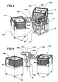
- Fig. 3 is a perspective view of the apparatus in Fig. 1, with the holding cage removed;
- Fig. 4 is a perspective view of the apparatus in Fig. 1, with the holding cage and the assembling station removed;
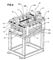
- Fig. 5 is an enlarged perspective view of the assembling station of the apparatus in Fig. 1;
- Fig. 6 is a perspective view of a grip member shown in Fig. 4;
- Fig. 7 is a top view of the grip member shown in Fig. 6, with an upper wall removed;
- Fig. 8 is a section taken along line VIII-VIII in Fig. 7;
- Fig. 9 is a top view of a drawer shown in Fig. 1.
- With reference to the drawings, an apparatus for making cards for multi-layered printed circuits in accordance with the present invention has been generally identified by
reference numeral 1. -
Apparatus 1 comprises an assemblingstation 2 in which at least two conductive layers and one insulating layer are superposed on each other in an alternated sequence and joined to form a multi-layered card. - The
assembling station 2 is preferably made up of asupport structure 3 on which an alignment table 4 extending in a horizontal plane is installed. The alignment table 4 has a dual function, i.e. that of supporting the card during assembling and of aligning the already joined conductive layers with each conductive layer added thereto. - The assembling
station 2 further comprises appropriate movement means 5 to move the table 4 relative to thesupport structure 3. In particular, said means 5 enables traversing of table 4 along two directions X, Y that are mutually orthogonal and parallel to the table 4 itself, as well as rotation of same relative to a vertical axis Z. - Preferably table 4 is of a rectangular shape and the two traverse directions X, Y are parallel to the sides of same.
- In addition, the vertical rotation axis Z is placed close to one of the minor sides and at a
symmetry axis 6 lying in the extension plane of table 4. - In order to keep the first conductive layer of the multi-layered card firmly fixed during laying down of the subsequent layers, table 4 is provided with a plurality of
holes 7 communicating with acavity 8 maintained under vacuum. - The vacuum in
cavity 8 generates a sucking effect ensuring adhesion of the first conductive layer to the alignment table 4. - An optical position-detecting device 10 is disposed above table 4, being supported by a
first frame 9 integral with thesupport structure 3. - Such a device comprises two aligned
optical detectors symmetry axis 6 of table 4. - In particular, a first
optical detector 10a is fastened to thefirst frame 9 and lies close to the rotation axis Z of table 4, whereas a secondoptical detector 10b is movable in a direction parallel to table 4 along atrack 11 mounted on thefirst frame 9. - The assembling
station 2 further comprises a plurality of welders mounted on asecond frame 13. Preferably, welders 12 are divided into twogroups - According to the embodiment shown, welders 12 of each
group bar symmetry axis 6 of table 4 and movable, onappropriate rails 15 mounted to thesecond frame 13, between the edges of table 4 and thesymmetry axis 6 of the table itself. - Each individual welder 12 is, in addition, movable in a vertical direction between a first non-operating position, in which it is spaced apart from table 4, and an operating position in which it is close to said table 4 so that it can weld two superposed conductive layers together.
-
Apparatus 1 in accordance with the invention further comprises afirst storing station 16a to store the conductive layers, before use, and asecond storing station 16b to store the insulating layers before use and lay down the multi-layered cards, once assembled. - Each
storing station holding frame 17, mounted onsupport wheels 18, in which a plurality of mutually superposeddrawers 19 are slidably inserted. Eachdrawer 19 is movable between a first position in which it is inserted inframe 17 and is piled up on the others, and a second position in which it is pulled out offrame 17 to enable either picking up of a conductive or insulating layer or deposit of a finished card. - Each
drawer 19 is provided with positioning means 20 enabling conductive layers, insulating layers or finished cards of different sizes to be kept at a predetermined position. - As shown in Fig. 9, said positioning means 20 comprises at least three
abutment elements 21 movable inrespective slide guides 22 formed in therest surface 23 ofdrawer 19. - Preferably, the
slide guides 22 are disposed symmetrically of amedian axis 24 exhibited by eachdrawer 19 so that layers of different formats to be assembled can be always blocked at the centre line of thedrawer 19 itself. - For the sake of clarity, two layers of different sizes identified by letters S and S' are shown in chain line in Fig. 9.
- The storing stations further comprise appropriate means for automatic movement of
drawers 19, not shown. - The
present apparatus 1 also comprises afirst grip member 25a, asecond grip member 25b and actuating means 26 for saidgrip members - The
first grip member 25a is movable in a horizontal direction between thefirst storing station 16a and the assemblingstation 2, to pick up a conductive layer and transfer it to the assemblingstation 2. - The
second grip member 25b is movable in a horizontal direction between the assemblingstation 2 and thesecond storing station 16b, to bring a finished card from the assemblingstation 2 to thesecond storing station 16b and, vice versa, to pick up an insulating layer and take it to the assemblingstation 2. - Advantageously, the actuating means 26 rigidly connects the
first grip member 25a tosecond grip member 25b in their horizontal movement. Therefore, while thefirst grip member 25a moves from thefirst storing station 16a to the assemblingstation 2, thesecond grip member 25b moves from the assemblingstation 2 to thesecond storing station 16b. - Vice versa, when the
first grip member 25a moves from the assemblingstation 2 to thefirst storing station 16a, thesecond grip member 25b moves from thesecond storing station 16b to the assemblingstation 2. - According to a preferred embodiment depicted in the accompanying drawings, the actuating means 26 comprises a
rotating support structure 27 on which the twogrip members Structure 27 rotates around its ownvertical axis 28 through an arc of a circle of 120°, therefore thegrip members - The
grip members structure 27 through respectivevertical guides - Therefore they can move in a vertical direction between an upper position, close to the
uppermost drawer 19, and a lower position, close to thelowermost drawer 19, through a plurality of intermediate positions at heights wherein the remainingdrawers 19 are disposed in the storingstations - The storing
stations 16, 16b and assemblingstation 2 are circumferentially distributed around thevertical axis 28 of therotating support structure 27 and mutually spaced apart by an angle of 120°, so that they can be reached by thegrip members vertical axis 26. - Advantageously, each of the two
grip members plate - Each
plate upper wall 31, alower wall 32, and at least oneside wall 33 that altogether bound achamber 34. In addition, thelower wall 32 has a plurality ofholes 35 for communication betweenchamber 34 and the surrounding atmosphere. - In the same manner as for the alignment table 4, appropriate sucking means, not shown, creates the vacuum in
chamber 34 so that the air sucked throughholes 35 enables seizure and holding fast of the conductive or insulating layers picked up from the storingstations station 2. - The maximum height that can be reached by
plates plates station 2, is vertically aligned with the table itself, so that table 4 andplates - In addition, the two
plates respective storing stations drawer 19 jutting out of from thecontainment frame 17. - Due to the operating mechanism, each
drawer 19 is approached from top by therespective plate lower wall 32 pierced with holes can get into contact with the upper layer in thedrawer 19 itself. - To enable the layers to be picked up without any interference with
drawer 19 or with theabutment elements 21, thelower wall 32 of eachplate rest surface 23 of eachdrawer 19. In addition, the upper 32 and lower 32 walls of each suckingplate passages 36 through theplate station 2. - These
passages 36 are defined by a plurality ofopenings 37 bounded bylateral sealing walls 33a disposed between theupper wall 31 andlower wall 32 at the edges of saidopenings 37. - In particular, to enable
welders 32 to place themselves close to table 4, while theplate plate - In accordance with the embodiment shown, the series of first openings 38 is divided into two
groups plate plate symmetry axis 39 exhibited by theplate - In addition, to enable pointing of the
optical detectors plate symmetry axis 39 of saidplates plate station 2, the second openings 40 are disposed along the action line of theoptical detectors - Finally, each sucking
plate abutment elements 21 ofdrawers 19 can be inserted. As illustrated in the accompanying drawings, the third openings 41 are three in number and are of elongated shape. A first one 41a of the third openings 41 lies on thesymmetry axis 39 ofplate first opening 41a and converge towards said first opening following a symmetrically-converging extension with respect to thesymmetry axis 39 of theplate - As highlighted in the figures, one 40a of the two second openings 40 is coincident with the first one 41a of the third openings 41, whereas the second one 40b of the second openings 40 is defined by a cavity formed in a minor side of
plate - Preferably, as viewed from the accompanying drawings, the assembling
station 2 andgrip members protection cage 42 to avoid the atmospheric agents damaging the conductive and insulating layers. - The storing
stations cage 42 so thatdrawers 19 when pulled out can be reached by the suckingplates - In addition, the apparatus is provided with
appropriate means 43 to removably secure each storingstation rotating support structure 27 during operation, for instance through members linking thestations cage 42. - Operation of the apparatus described above mainly as regards structure is as follows.
-
Drawer 19 in which the first conductive layer is placed is opened and the first suckingplate 30a, vertically aligned with the pulled outdrawer 19, comes down until it rests on the layer. The sucking means creates the vacuum inchamber 34 so that the air sucked up throughholes 35 holds the layer firmly on thelower surface 32 of thefirst plate 30a. - Subsequently
plate 30a rises to the upper position and rotates through 120° until it is in superposed relationship with the alignment table 4 between the table 4 itself and theoptical detectors - The sucking means of table 4 is started and that of the
first plate 30a is shut off so that the layer is laid down on the table and keeps a steady position thereon. - Simultaneously, while the
first plate 30a is over plate 4, thesecond plate 30b, interlocked with the first one 30a in its rotatory motion, picks up an insulating layer from thesecond storing station 16b. - At this point the two plates rotate through 120° in opposite ways, the first one 30a going back to the
first storing station 16b, to pick up a second conductive layer and the second one 30b going back to the region over the alignment table 4 while carrying an insulating layer on itslower wall 32. - Since a precise alignment of the insulating layer is not required, the
second plate 30b merely puts the insulating layer down onto the first conductive layer already attached to table 4. - During the subsequent rotation, the
first plate 30a brings the second conductive layer, just picked up, over plate 4 on which the first conductive layer and an insulating layer are already disposed. - With the second conductive layer being held on the
first plate 30a and through movement of the alignment table 4, the two conductive layers are aligned at their optical references. - At this point welders 12 come down through the first openings 38 of the
first plate 30a and press the second conductive layer against the first conductive layer, heating the insulating layer interposed therebetween that partly melts and, in the subsequent solidification step, joins the two conductive layers together. - The aligning and joining cycle is repeated following the above described steps until superposition of the necessary number of layers.
- When the last conductive layer has been fastened, the second sucking
plate 30b hooks up the whole card, released from table 4 and carries it to thesecond storing station 16b. - The present invention achieves important advantages.
- First of all, the apparatus in accordance with the invention is compact and can be positioned in rooms of small sizes.
- In fact, the layers and/or cards, even if of different types, are all contained in two storing stations alone extending in a vertical direction.
- In addition, the storing positions of the layers and finished cards, close to the assembling station, enable the spaces occupied by the grip members to be reduced, which will bring about a structural simplification and a reduction in downtime.
- Also placement of the table at an upper position with respect to the drawers promotes speeding up of the operations. In fact, the grip member after approaching the drawer from top and carrying out the subsequent picking up, can move towards the upper position without waiting for the drawer being retracted.
- Still, the layers are carried to the assembling station during each rotation of the support structure so that no return movements occur, the only function of them being that of bringing the grip members back to the storing stations to hook up a further layer.
- In addition, the drawers in accordance with the invention accept layers of different sizes and enable passage to production of cards of different formats without being obliged to stop the machine due to change of the layer type; in fact it is only sufficient to select the pre-set software management parameters.
- At all events, even when replacement of the storing stations is required, the operation is very quick since said stations are removably mounted to the apparatus and run on wheels.
- Finally, the sucking plates of the apparatus of the invention are such shaped that they can manage layers and cards of different formats without any modifications being required.
- In fact, the vacuum generated in the plate chamber is sufficient to firmly hold even layers of small sizes leaving most of the holes of the sucking plate uncovered.
- In addition, the openings formed in each plate enable the welders and optical detectors to intervene at the most appropriate positions depending on sizes.
Claims (23)
- An apparatus for making multi-layered cards for printed circuits, comprising:an assembling station (2) for the conductive and insulating layers;a first storing station (16a) for the conductive layers;a second storing station (16b) for the insulating layers;a first grip member (25a) movable in a horizontal direction between the first storing station (16a) and the assembling station (2) to pick up one conductive layer and transfer it to the assembling station (2);a second grip member (25b) movable in a horizontal direction between the second storing station (16b) and the assembling station (2), to pick up one insulating layer and transfer it to the assembling station (2);means (26) for actuating the grip members (25a, 25b); characterized in that said actuating means (26) rigidly connects the first grip member (25a) with the second grip member (25b) in a horizontal movement.
- An apparatus as claimed in claim 1, characterized in that the actuating means (26) comprises a support structure (29) rotating about a vertical axis (28).
- An apparatus as claimed in claim 2, characterized in that each grip member (25a, 25b) is slidably mounted on the rotating support structure (27) and movable between an upper position and a lower position.
- An apparatus as claimed in claim 2, characterized in that said first and second storing stations (16a, 16b) and assembling station (2) are circumferentially distributed around the vertical axis (28) of the rotating support structure (27).
- An apparatus as claimed in claim 4, characterized in that said first and second storing stations (16a, 16b) and assembling station (2) are mutually spaced apart through an arc of a circle of 120°.
- An apparatus as claimed in claim 2, characterized in that it further comprises means (43) for removably fastening the storing stations (16a, 16b) in their operating positions close to the rotating support structure (27).
- An apparatus as claimed in claim 1, characterized in that each of said grip members (25a, 25b) comprises a horizontal sucking plate (30a, 30b) of substantially rectangular shape.
- An apparatus as claimed in claim 7, characterized in that each sucking plate (30a, 30b) comprises an upper wall (31), a lower wall (32) and at least one side wall (33); the side wall (33) defining, in association with the upper wall (31) and lower wall (32), a chamber (34) at the inside of said plate (30a, 30b) which is adapted to be connected with suction means to create the vacuum in said chamber (34); the lower wall (32) further having a plurality of holes (35) for communication between the chamber (34) and the surrounding atmosphere.
- An apparatus as claimed in claim 8, characterized in that said first storing station (16a) and second storing station (16b) respectively comprise:a frame (17);a plurality of mutually-superposed drawers (19) each having a rest surface (23) for the conductive layers or the insulating layers, each of said drawers (19) being slidably movable between a first position in which the drawer (19) is inserted in the frame (17) and a second position in which the drawer (19) juts out of the frame (17).
- An apparatus as claimed in claim 9, characterized in that the first and second grip members (25a, 25b) placed at the respective storing stations (16a, 16b) are in vertical alignment with each drawer (19) jutting out of the frame (17) in said second position.
- An apparatus as claimed in claim 9, characterized in that the rest surface (23) of each drawer (19) substantially has the same sizes as the lower wall (32) of each plate (30a, 30b), for the purpose of associating the plate (30a, 30b) with the drawer (19) during picking up of one conductive or insulating layer.
- An apparatus as claimed in claim 9, characterized in that each drawer (19) comprises abutment elements (21) movable in respective slide guides (22), to store layers or multi-layered cards of different sizes.
- An apparatus as claimed in claim 12, characterized in that said slide guides (22) are formed in the rest surface (23) of each drawer (19) and are symmetrically disposed relative to a median axis (24) exhibited by each drawer (19).
- An apparatus as claimed in claim 7, characterized in that the assembling station (2) comprises:a support structure (3);an alignment table (4) installed on the support structure (3);means (5) to traverse and rotate the alignment table (4) along the support structure (3) in a plane parallel to the table (4) itself;at least one optical position-detecting device (10) placed over the alignment table (4);a plurality of welders (12) set over the alignment table (4), each of said welders (12) being movable between a first position in which it is spaced apart from the table (4) and a second position in which it is close to said table (4).
- An apparatus as claimed in claim 14, characterized in that each grip member (25a, 25b), placed at the assembling station (2), is in superposed relationship with the alignment table (4).
- An apparatus as claimed in claim 14, characterized in that said optical position-detecting device (10) comprises at least two optical detectors (10a, 10b) aligned at a symmetry axis (6) exhibited by the table (4) itself.
- An apparatus as claimed in claim 16, characterized in that at least one of said optical detectors (10a, 10b) is movable parallel to said table (4) and along the symmetry axis (6) of said table (4).
- An apparatus as claimed in claim 14, characterized in that the welders (12) are symmetrically arranged relative to the symmetry axis (6) of the table (4) and movable between the edges of the table (4) and the symmetry axis (6) of said table (4), to fit the layer sizes.
- An apparatus as claimed in claim 8, characterized in that the upper (31) and lower (32) walls of each sucking plate (30a, 30b) have a plurality of passages (36) through said sucking plate (3a0, 30b) distributed at least along two mutually orthogonal directions thereof.
- An apparatus as claimed in claim 19, characterized in that the passages (36) of each sucking plate (30a, 30b) are defined by a plurality of openings (37) formed in the upper (31) and lower (32) walls and bounded by lateral sealing walls (33a); the lateral sealing walls (33a) being disposed between the upper wall (31) and lower wall (32) and at the edges of said openings (37).
- An apparatus as claimed in claim 14, characterized in that each sucking plate (30a, 30b) has a series of first openings (38) for passage of the welders (12); said first openings (38) being placed along two mutually opposite sides of the sucking plate (3a0, 30b) and each having an elongated conformation in a perpendicular direction relative to a symmetry axis (39) of the plate (30a, 30b) itself.
- An apparatus as claimed in claim 14, characterized in that each sucking plate (30a, 30b) has a series of second openings (40) disposed on a symmetry axis (39) of the plate (30a, 30b) itself for pointing of the optical detectors (10a, 10b).
- An apparatus as claimed in claim 12, characterized in that each sucking plate (30a, 30b) has a series of third openings (41) for passage of the abutment elements (21) of the drawers (19); at least two of said third openings (41) having an elongated shape, according to an extension symmetrically converging with respect to a symmetry axis (39) exhibited by the plate (30a, 30b) itself.
Priority Applications (3)
| Application Number | Priority Date | Filing Date | Title |
|---|---|---|---|
| AT01830478T ATE288671T1 (en) | 2001-07-19 | 2001-07-19 | DEVICE FOR PRODUCING MULTI-LAYER CIRCUIT BOARDS |
| EP01830478A EP1278406B1 (en) | 2001-07-19 | 2001-07-19 | Apparatus for making multi-layered printed circuits |
| DE60108736T DE60108736T2 (en) | 2001-07-19 | 2001-07-19 | Device for producing multilayer circuit boards |
Applications Claiming Priority (1)
| Application Number | Priority Date | Filing Date | Title |
|---|---|---|---|
| EP01830478A EP1278406B1 (en) | 2001-07-19 | 2001-07-19 | Apparatus for making multi-layered printed circuits |
Publications (2)
| Publication Number | Publication Date |
|---|---|
| EP1278406A1 EP1278406A1 (en) | 2003-01-22 |
| EP1278406B1 true EP1278406B1 (en) | 2005-02-02 |
Family
ID=8184621
Family Applications (1)
| Application Number | Title | Priority Date | Filing Date |
|---|---|---|---|
| EP01830478A Expired - Lifetime EP1278406B1 (en) | 2001-07-19 | 2001-07-19 | Apparatus for making multi-layered printed circuits |
Country Status (3)
| Country | Link |
|---|---|
| EP (1) | EP1278406B1 (en) |
| AT (1) | ATE288671T1 (en) |
| DE (1) | DE60108736T2 (en) |
Families Citing this family (1)
| Publication number | Priority date | Publication date | Assignee | Title |
|---|---|---|---|---|
| ITMI20131352A1 (en) * | 2013-08-07 | 2015-02-08 | Ivision S R L Con Socio Unico | EQUIPMENT FOR PANEL HANDLING |
Family Cites Families (2)
| Publication number | Priority date | Publication date | Assignee | Title |
|---|---|---|---|---|
| DE9317228U1 (en) * | 1993-11-10 | 1994-03-10 | Kuttler Handhabungstechnik GmbH, 78083 Dauchingen | Device for handling printed circuit boards |
| DE19628163C2 (en) * | 1995-07-22 | 2000-09-07 | Kuttler Hans Juergen | Device for the fully automatic, pinless production of multilayer press assemblies |
-
2001
- 2001-07-19 EP EP01830478A patent/EP1278406B1/en not_active Expired - Lifetime
- 2001-07-19 DE DE60108736T patent/DE60108736T2/en not_active Expired - Lifetime
- 2001-07-19 AT AT01830478T patent/ATE288671T1/en not_active IP Right Cessation
Also Published As
| Publication number | Publication date |
|---|---|
| DE60108736T2 (en) | 2005-06-23 |
| ATE288671T1 (en) | 2005-02-15 |
| EP1278406A1 (en) | 2003-01-22 |
| DE60108736D1 (en) | 2005-03-10 |
Similar Documents
| Publication | Publication Date | Title |
|---|---|---|
| CN110891881B (en) | Transport vehicle and transport facility | |
| CA2164183C (en) | Stacking board for depositing a stack of sheets, and automatic handling apparatus for stacking boards of this type | |
| CN113165805A (en) | Transport of container handling vehicles between storage grids at different heights | |
| US20100023159A1 (en) | Palleting device and a processing system with such device | |
| EP0452159B1 (en) | Parts tray conveying system | |
| US7316060B2 (en) | System for populating a circuit board with semiconductor chips | |
| EP1278406A1 (en) | Apparatus for making multi-layered printed circuits | |
| CN107081759B (en) | Flexible assembly system for dished prize disc | |
| JP5236797B2 (en) | Transport system for workpiece processing | |
| KR102579746B1 (en) | A System for Delivering a Tray Stack | |
| JP4380853B2 (en) | Plate material loading / unloading device for thermal cutting machine | |
| CN221262327U (en) | Automatic conveying and stacking container | |
| US5725347A (en) | Carousel pin stacker | |
| CN110271702A (en) | A kind of material strip packing machine of accurate relaying positioning | |
| JP3574977B2 (en) | Method and apparatus for loading a copper-clad ceramic substrate into a processing unit | |
| CN115892915A (en) | Method and system for automatically stacking panels | |
| JPH07143706A (en) | Automatic lamination device for segment cores for stator cores | |
| CN223421871U (en) | Palletizing module and palletizing machine for cigarette package palletizing | |
| JPS58137538A (en) | Automatic tool exchanger | |
| CN218753497U (en) | Automatic cave-dividing, disc-arranging and disc-changing device | |
| CN220055311U (en) | Conveying mechanism, discharging device and carrier plate operation system | |
| JPH05294455A (en) | Pallet changer | |
| CN214651924U (en) | Type-C plug iron-clad separation balance equipment | |
| JPH04267111A (en) | Mold exchanging system | |
| EP1279469B1 (en) | Vacuum gripper to be used for the manufacture of multi-layered printed circuits |
Legal Events
| Date | Code | Title | Description |
|---|---|---|---|
| PUAI | Public reference made under article 153(3) epc to a published international application that has entered the european phase |
Free format text: ORIGINAL CODE: 0009012 |
|
| 17P | Request for examination filed |
Effective date: 20020130 |
|
| AK | Designated contracting states |
Kind code of ref document: A1 Designated state(s): AT BE CH CY DE DK ES FI FR GB GR IE IT LI LU MC NL PT SE TR |
|
| AX | Request for extension of the european patent |
Free format text: AL;LT;LV;MK;RO;SI |
|
| AKX | Designation fees paid |
Designated state(s): AT BE CH CY DE DK ES FI FR GB GR IE IT LI LU MC NL PT SE TR |
|
| GRAP | Despatch of communication of intention to grant a patent |
Free format text: ORIGINAL CODE: EPIDOSNIGR1 |
|
| GRAS | Grant fee paid |
Free format text: ORIGINAL CODE: EPIDOSNIGR3 |
|
| GRAA | (expected) grant |
Free format text: ORIGINAL CODE: 0009210 |
|
| RAP1 | Party data changed (applicant data changed or rights of an application transferred) |
Owner name: TAPEMATIC S.P.A. |
|
| AK | Designated contracting states |
Kind code of ref document: B1 Designated state(s): AT BE CH CY DE DK ES FI FR GB GR IE IT LI LU MC NL PT SE TR |
|
| PG25 | Lapsed in a contracting state [announced via postgrant information from national office to epo] |
Ref country code: BE Free format text: LAPSE BECAUSE OF FAILURE TO SUBMIT A TRANSLATION OF THE DESCRIPTION OR TO PAY THE FEE WITHIN THE PRESCRIBED TIME-LIMIT Effective date: 20050202 Ref country code: LI Free format text: LAPSE BECAUSE OF FAILURE TO SUBMIT A TRANSLATION OF THE DESCRIPTION OR TO PAY THE FEE WITHIN THE PRESCRIBED TIME-LIMIT Effective date: 20050202 Ref country code: NL Free format text: LAPSE BECAUSE OF FAILURE TO SUBMIT A TRANSLATION OF THE DESCRIPTION OR TO PAY THE FEE WITHIN THE PRESCRIBED TIME-LIMIT Effective date: 20050202 Ref country code: AT Free format text: LAPSE BECAUSE OF FAILURE TO SUBMIT A TRANSLATION OF THE DESCRIPTION OR TO PAY THE FEE WITHIN THE PRESCRIBED TIME-LIMIT Effective date: 20050202 Ref country code: TR Free format text: LAPSE BECAUSE OF FAILURE TO SUBMIT A TRANSLATION OF THE DESCRIPTION OR TO PAY THE FEE WITHIN THE PRESCRIBED TIME-LIMIT Effective date: 20050202 Ref country code: CH Free format text: LAPSE BECAUSE OF FAILURE TO SUBMIT A TRANSLATION OF THE DESCRIPTION OR TO PAY THE FEE WITHIN THE PRESCRIBED TIME-LIMIT Effective date: 20050202 Ref country code: FI Free format text: LAPSE BECAUSE OF FAILURE TO SUBMIT A TRANSLATION OF THE DESCRIPTION OR TO PAY THE FEE WITHIN THE PRESCRIBED TIME-LIMIT Effective date: 20050202 Ref country code: FR Free format text: LAPSE BECAUSE OF NON-PAYMENT OF DUE FEES Effective date: 20050202 |
|
| REG | Reference to a national code |
Ref country code: GB Ref legal event code: FG4D |
|
| REG | Reference to a national code |
Ref country code: CH Ref legal event code: EP |
|
| REG | Reference to a national code |
Ref country code: IE Ref legal event code: FG4D |
|
| REF | Corresponds to: |
Ref document number: 60108736 Country of ref document: DE Date of ref document: 20050310 Kind code of ref document: P |
|
| PG25 | Lapsed in a contracting state [announced via postgrant information from national office to epo] |
Ref country code: DK Free format text: LAPSE BECAUSE OF FAILURE TO SUBMIT A TRANSLATION OF THE DESCRIPTION OR TO PAY THE FEE WITHIN THE PRESCRIBED TIME-LIMIT Effective date: 20050502 Ref country code: GR Free format text: LAPSE BECAUSE OF FAILURE TO SUBMIT A TRANSLATION OF THE DESCRIPTION OR TO PAY THE FEE WITHIN THE PRESCRIBED TIME-LIMIT Effective date: 20050502 Ref country code: SE Free format text: LAPSE BECAUSE OF FAILURE TO SUBMIT A TRANSLATION OF THE DESCRIPTION OR TO PAY THE FEE WITHIN THE PRESCRIBED TIME-LIMIT Effective date: 20050502 |
|
| PG25 | Lapsed in a contracting state [announced via postgrant information from national office to epo] |
Ref country code: ES Free format text: LAPSE BECAUSE OF FAILURE TO SUBMIT A TRANSLATION OF THE DESCRIPTION OR TO PAY THE FEE WITHIN THE PRESCRIBED TIME-LIMIT Effective date: 20050513 |
|
| PG25 | Lapsed in a contracting state [announced via postgrant information from national office to epo] |
Ref country code: IE Free format text: LAPSE BECAUSE OF NON-PAYMENT OF DUE FEES Effective date: 20050719 Ref country code: LU Free format text: LAPSE BECAUSE OF NON-PAYMENT OF DUE FEES Effective date: 20050719 Ref country code: GB Free format text: LAPSE BECAUSE OF NON-PAYMENT OF DUE FEES Effective date: 20050719 Ref country code: CY Free format text: LAPSE BECAUSE OF FAILURE TO SUBMIT A TRANSLATION OF THE DESCRIPTION OR TO PAY THE FEE WITHIN THE PRESCRIBED TIME-LIMIT Effective date: 20050719 |
|
| PG25 | Lapsed in a contracting state [announced via postgrant information from national office to epo] |
Ref country code: MC Free format text: LAPSE BECAUSE OF NON-PAYMENT OF DUE FEES Effective date: 20050731 |
|
| NLV1 | Nl: lapsed or annulled due to failure to fulfill the requirements of art. 29p and 29m of the patents act | ||
| REG | Reference to a national code |
Ref country code: CH Ref legal event code: PL |
|
| PLBE | No opposition filed within time limit |
Free format text: ORIGINAL CODE: 0009261 |
|
| STAA | Information on the status of an ep patent application or granted ep patent |
Free format text: STATUS: NO OPPOSITION FILED WITHIN TIME LIMIT |
|
| 26N | No opposition filed |
Effective date: 20051103 |
|
| GBPC | Gb: european patent ceased through non-payment of renewal fee |
Effective date: 20050719 |
|
| EN | Fr: translation not filed | ||
| REG | Reference to a national code |
Ref country code: IE Ref legal event code: MM4A |
|
| PGFP | Annual fee paid to national office [announced via postgrant information from national office to epo] |
Ref country code: IT Payment date: 20060731 Year of fee payment: 6 |
|
| PG25 | Lapsed in a contracting state [announced via postgrant information from national office to epo] |
Ref country code: PT Free format text: LAPSE BECAUSE OF NON-PAYMENT OF DUE FEES Effective date: 20050702 |
|
| PG25 | Lapsed in a contracting state [announced via postgrant information from national office to epo] |
Ref country code: IT Free format text: LAPSE BECAUSE OF NON-PAYMENT OF DUE FEES Effective date: 20070719 |
|
| PGFP | Annual fee paid to national office [announced via postgrant information from national office to epo] |
Ref country code: DE Payment date: 20100930 Year of fee payment: 10 |
|
| PG25 | Lapsed in a contracting state [announced via postgrant information from national office to epo] |
Ref country code: DE Free format text: LAPSE BECAUSE OF NON-PAYMENT OF DUE FEES Effective date: 20120201 |
|
| REG | Reference to a national code |
Ref country code: DE Ref legal event code: R119 Ref document number: 60108736 Country of ref document: DE Effective date: 20120201 |