EP1278316A1 - Dispersion compensator - Google Patents
Dispersion compensator Download PDFInfo
- Publication number
- EP1278316A1 EP1278316A1 EP01912318A EP01912318A EP1278316A1 EP 1278316 A1 EP1278316 A1 EP 1278316A1 EP 01912318 A EP01912318 A EP 01912318A EP 01912318 A EP01912318 A EP 01912318A EP 1278316 A1 EP1278316 A1 EP 1278316A1
- Authority
- EP
- European Patent Office
- Prior art keywords
- dispersion
- compensating
- optical fibers
- compensating optical
- optical fiber
- Prior art date
- Legal status (The legal status is an assumption and is not a legal conclusion. Google has not performed a legal analysis and makes no representation as to the accuracy of the status listed.)
- Granted
Links
Images




Classifications
-
- G—PHYSICS
- G02—OPTICS
- G02B—OPTICAL ELEMENTS, SYSTEMS OR APPARATUS
- G02B6/00—Light guides; Structural details of arrangements comprising light guides and other optical elements, e.g. couplings
- G02B6/10—Light guides; Structural details of arrangements comprising light guides and other optical elements, e.g. couplings of the optical waveguide type
- G02B6/12—Light guides; Structural details of arrangements comprising light guides and other optical elements, e.g. couplings of the optical waveguide type of the integrated circuit kind
-
- G—PHYSICS
- G02—OPTICS
- G02B—OPTICAL ELEMENTS, SYSTEMS OR APPARATUS
- G02B6/00—Light guides; Structural details of arrangements comprising light guides and other optical elements, e.g. couplings
- G02B6/24—Coupling light guides
- G02B6/26—Optical coupling means
- G02B6/28—Optical coupling means having data bus means, i.e. plural waveguides interconnected and providing an inherently bidirectional system by mixing and splitting signals
- G02B6/293—Optical coupling means having data bus means, i.e. plural waveguides interconnected and providing an inherently bidirectional system by mixing and splitting signals with wavelength selective means
- G02B6/29371—Optical coupling means having data bus means, i.e. plural waveguides interconnected and providing an inherently bidirectional system by mixing and splitting signals with wavelength selective means operating principle based on material dispersion
- G02B6/29374—Optical coupling means having data bus means, i.e. plural waveguides interconnected and providing an inherently bidirectional system by mixing and splitting signals with wavelength selective means operating principle based on material dispersion in an optical light guide
- G02B6/29376—Optical coupling means having data bus means, i.e. plural waveguides interconnected and providing an inherently bidirectional system by mixing and splitting signals with wavelength selective means operating principle based on material dispersion in an optical light guide coupling light guides for controlling wavelength dispersion, e.g. by concatenation of two light guides having different dispersion properties
-
- H—ELECTRICITY
- H04—ELECTRIC COMMUNICATION TECHNIQUE
- H04B—TRANSMISSION
- H04B10/00—Transmission systems employing electromagnetic waves other than radio-waves, e.g. infrared, visible or ultraviolet light, or employing corpuscular radiation, e.g. quantum communication
- H04B10/25—Arrangements specific to fibre transmission
- H04B10/2507—Arrangements specific to fibre transmission for the reduction or elimination of distortion or dispersion
- H04B10/2513—Arrangements specific to fibre transmission for the reduction or elimination of distortion or dispersion due to chromatic dispersion
- H04B10/2525—Arrangements specific to fibre transmission for the reduction or elimination of distortion or dispersion due to chromatic dispersion using dispersion-compensating fibres
Definitions
- the present invention relates to a dispersion compensator for compensating for the chromatic dispersion and dispersion slope of an optical fiber transmission line; and an optical transmission system comprising an optical fiber transmission line and a dispersion compensator.
- the accumulated chromatic dispersion of the optical fiber transmission line In optical transmission systems carrying out optical communications by propagating signal light through an optical fiber transmission line, it is desired that the accumulated chromatic dispersion of the optical fiber transmission line have a small absolute value at the signal light wavelength (e.g., 1.55 ⁇ m) in order to suppress the waveform deterioration of the signal light when it propagates through the optical fiber transmission line.
- WDM wavelength division multiplexing
- the accumulated chromatic dispersion of the optical fiber transmission line should be small in a signal light wavelength band including individual wavelengths of the plurality of wavelengths of signal light. Namely, it is desirable for the optical fiber transmission line to have not only a small absolute value of chromatic dispersion but also a small absolute value of dispersion slope in the signal light wavelength band.
- typical single-mode optical fibers employed as optical fiber transmission lines in general have a zero-dispersion wavelength near a wavelength of 1.3 ⁇ m, while having a chromatic dispersion of about 17 ps/nm/km and a dispersion slope of about 0.058 ps/nm 2 /km at a wavelength of 1.55 ⁇ m.
- both the chromatic dispersion and dispersion slope of the dispersion-compensating optical fiber should be designed appropriately according to the length ratio between the single-mode optical fiber and the dispersion-compensating optical fiber and the chromatic dispersion characteristic of the single-mode optical fiber, and that the dispersion-compensating optical fiber be manufactured as designed.
- the chromatic dispersion characteristic of the dispersion-compensating optical fiber is quite sensitive to changes in the drawing tension and core diameter in the longitudinal direction at the time when its optical fiber preform is drawn.
- the processing precision of the optical fiber preform may not be sufficient, and the accuracy in measurement of refractive index distribution in the optical fiber preform carried out by a preform analyzer is may not be sufficient, either. Therefore, it is difficult for a dispersion-compensating optical fiber having the aimed chromatic dispersion characteristic to be manufactured with a high precision.
- the dispersion slope compensation ratio ⁇ is ideally desired to be 100%, the dispersion slope compensation ratio ⁇ may fluctuate among actually manufactured dispersion-compensating optical fibers approximately within the range of 50% to 120% with its average value being about 90%.
- the dispersion slope compensation ratio ⁇ is an index representing the degree of compensation when a dispersion-compensating optical fiber compensates for the chromatic dispersion and dispersion slope of a single-mode optical fiber.
- dispersion slope compensation ratio ⁇ of an actually manufactured dispersion-compensating optical fiber greatly differs from the ideal value of 100%, then this dispersion-compensating optical fiber cannot fully compensate for the chromatic dispersion and dispersion slope of the single-mode optical fiber. In this case, it is hard to carry out WDM transmission over a wide band and optical transmission with a high bit rate (e.g., 40 Gb/s).
- the dispersion slope compensation ratio ⁇ of each of manufactured dispersion-compensating optical fibers may be measured, so as to selectively use those whose dispersion slope compensation ratio ⁇ lies within a predetermined range.
- this procedure is undesirable in that the yield is not favorable, so that the price of conforming products becomes higher.
- the dispersion compensator in accordance with the present invention is a dispersion compensator for compensating for the chromatic dispersion and dispersion slope of an optical fiber transmission line in which a plurality of dispersion-compensating optical fibers each having a dispersion slope compensation ratio of at least 60% with respect to the optical fiber transmission line at a predetermined wavelength (e.g., 1.55 ⁇ m) are connected to each other, one of the plurality of dispersion-compensating optical fibers has a dispersion slope compensation ratio of at least 80%, and another of the plurality of dispersion-compensating optical fibers has a dispersion slope compensation ratio within the range of 60% to 100%.
- a predetermined wavelength e.g., 1.55 ⁇ m
- the average dispersion slope compensation ratio of this dispersion compensator is an average value of the respective dispersion slope compensation ratios of the plurality of dispersion-compensating optical fibers in a certain sense, and can become a value near 100% if the ratio of respective lengths of the plurality of dispersion-compensating optical fibers is appropriately set.
- the dispersion compensator can fully compensate for both the chromatic dispersion and dispersion slope of the optical fiber transmission line.
- the dispersion slope compensation ratio ⁇ of each dispersion-compensating optical fiber is measured after manufacture, and a plurality of dispersion-compensating optical fibers are connected according to results of the measurement so as to construct the dispersion compensator as mentioned above.
- the manufactured dispersion-compensating optical fibers can be used efficiently, whereby the dispersion compensator becomes inexpensive.
- the average dispersion slope compensation ratio of the plurality of dispersion-compensating optical fibers may be at least 80%.
- the dispersion compensator can fully compensate for both the chromatic dispersion and dispersion slope of the optical fiber transmission line.
- a plurality of dispersion-compensating optical fibers may be connected in the order of increasing effective area thereof.
- signal light having a higher power propagates through a dispersion-compensating optical fiber having a relatively larger effective area, so that the generation of nonlinear optical phenomena can be suppressed, whereby transmission characteristics become excellent.
- first and second dispersion-compensating optical fibers cascaded to each other may be fusion-spliced to each other.
- the splice loss between the first and second dispersion-compensating optical fibers is low.
- the fusion-spliced portion between the first and second dispersion-compensating optical fibers be re-coated with a resin material having a coating diameter substantially equal to the coating diameter of each of the first and second dispersion-compensating optical fibers, and be wound about a bobbin together with the first and second dispersion-compensating optical fibers.
- the fusion-spliced portion between the first and second dispersion-compensating optical fibers be re-coated with a resin material and be secured with reinforcement means. It is also preferred that the plurality of dispersion-compensating optical fibers be contained in a bundle state free of any body portion substantially in contact therewith. In any of these cases, each of the plurality of dispersion-compensating optical fibers can be contained in a compact state while securing a mechanical strength in the fusion-spliced portion and suppressing the increase in transmission loss.
- the optical transmission system in accordance with the present invention comprises an optical fiber transmission line for transmitting signal light; and the above-mentioned dispersion compensator, in which a plurality of dispersion-compensating optical fibers are connected to each other, for compensating for the chromatic dispersion and dispersion slope of the optical fiber transmission line.
- the dispersion compensator compensates for the chromatic dispersion and dispersion slope of the optical fiber transmission line, whereby the respective absolute values of the average chromatic dispersion and average dispersion slope of the optical fiber transmission line and dispersion compensator are lowered.
- this optical transmission system can carry out WDM transmission over a wide band and optical transmission with a high bit rate.
- the optical transmission system in accordance with the present invention may be configured such that a plurality of dispersion-compensating optical fibers are connected in the order of increasing effective area thereof, and that signal light is fed from the side of the dispersion-compensating optical fiber having a larger effective area.
- the occurrence of nonlinear optical phenomena can be suppressed in the dispersion compensator, whereby transmission characteristics become excellent.
- FIG. 1 is a schematic block diagram of the optical transmission system 1 in accordance with an embodiment.
- an optical fiber transmission line 30 is laid between a transmitter station (or repeater station) 10 and a receiver station (or repeater station) 20.
- a transmitter station or repeater station
- a receiver station or repeater station
- an optical amplifier 21 a dispersion compensator 22
- an optical amplifier 23 an optical amplifier 23
- a receiver 24 Provided within the receiver station 20 are an optical amplifier 21, a dispersion compensator 22, an optical amplifier 23, and a receiver 24.
- signal light sent out from the transmitter station 10 propagates through the optical fiber transmission line 30 and reaches the receiver station 20.
- the signal light having reached the receiver station 20 is optically amplified by the optical amplifier 21, the dispersion of the amplified light is compensated for by the dispersion compensator 22, thus obtained light is optically amplified by the optical amplifier 23, and then the amplified light is received by the receiver 24.
- the optical fiber transmission line 30 As the optical fiber transmission line 30, a typical single-mode optical fiber having a zero-dispersion wavelength near a wavelength of 1.3 ⁇ m is used, for example. In this case, at a signal light wavelength of 1.55 ⁇ m, the optical fiber transmission line 30 has a chromatic dispersion of about 17 ps/nm/km and a dispersion slope of about 0.058 ps/nm 2 /km.
- Each of the optical amplifiers 21 and 23 optically amplifies the signal light fed therein and outputs the amplified signal light.
- an optical fiber amplifier EDFA: Erbium Doped Fiber Amplifier
- EDFA Erbium Doped Fiber Amplifier
- the dispersion compensator 22 compensates for the chromatic dispersion and dispersion slope of the optical fiber transmission line 30. Namely, at a signal light wavelength of 1.55 ⁇ m, the dispersion compensator 22 has a chromatic dispersion with an opposite sign of the chromatic dispersion of the optical fiber transmission line 30, and a dispersion slope with an opposite sign of the dispersion slope of the optical fiber transmission line 30. In the case where the optical fiber transmission line 30 is a single-mode optical fiber, both the chromatic dispersion and dispersion slope of the dispersion compensator 22 are negative at a signal light wavelength of 1.55 ⁇ m.
- the dispersion compensator 22 is constituted by a plurality of dispersion-compensating optical fibers connected to each other.
- the dispersion compensator 22 is constituted by two kinds of dispersion-compensating optical fibers 221 and 222 which are connected to each other.
- Each of the dispersion-compensating optical fibers 221 and 222 has a dispersion slope compensation ratio of at least 60%.
- One of the dispersion-compensating optical fibers 221 and 222 has a dispersion slope compensation ratio of at least 80%, whereas the other has a dispersion slope compensation ratio within the range of 60% to 100%.
- the upper limit of the dispersion slope compensation ratio in each of the dispersion-compensating optical fibers 221 and 222 is about 150% in practice.
- Fig. 2 is an explanatory view of the dispersion compensator 22 in accordance with this embodiment.
- L 1 , D 1 , S 1 , ⁇ 1 , and A 1 be the length, chromatic dispersion, dispersion slope, dispersion slope compensation ratio, and effective area of the dispersion-compensating optical fiber 221 on the upstream side, respectively.
- L 2 , D 2 , S 2 , ⁇ 2 , and A 2 be the length, chromatic dispersion, dispersion slope, dispersion slope compensation ratio, and effective area of the dispersion-compensating optical fiber 222 on the downstream side, respectively.
- Fig. 3 is an explanatory chart of specific examples of the dispersion compensator 22 in accordance with this embodiment. This chart shows three cases of the dispersion compensator 22 at a wavelength of 1.55 ⁇ m.
- Case 1 indicates an example having dispersion-compensating optical fibers A, B as the dispersion-compensating optical fibers 221, 222.
- the dispersion-compensating optical fiber A has a chromatic dispersion of -120 ps/nm/km and a dispersion slope compensation ratio of 120%.
- the dispersion-compensating optical fiber B has a chromatic dispersion of -120 ps/nm/km and a dispersion slope compensation ratio of 80%.
- the length ratio of the dispersion-compensating optical fibers A and B is 1:1.
- the dispersion-compensator 22 in which the dispersion-compensating optical fibers A and B are connected to each other has an average chromatic dispersion of -120 ps/nm/km and an average dispersion slope compensation ratio ⁇ ave of 100%.
- Case 2 indicates an example having dispersion-compensating optical fibers C, D as the dispersion-compensating optical fibers 221, 222.
- the dispersion-compensating optical fiber C has a chromatic dispersion of -140 ps/nm/km and a dispersion slope compensation ratio of 120%.
- the dispersion-compensating optical fiber D has a chromatic dispersion of -80 ps/nm/km and a dispersion slope compensation ratio of 70%.
- the length ratio of the dispersion-compensating optical fibers C and D is 2:3.
- the dispersion compensator 22 in which the dispersion-compensating optical fibers C and D are connected to each other has an average chromatic dispersion of -104 ps/nm/km and an average dispersion slope compensation ratio ⁇ ave of 98%.
- Case 3 indicates an example having dispersion-compensating optical fibers E, F as the dispersion-compensating optical fibers 221, 222.
- the dispersion-compensating optical fiber E has a chromatic dispersion of -80 ps/nm/km and a dispersion slope compensation ratio of 120%.
- the dispersion-compensating optical fiber F has a chromatic dispersion of -80 ps/nm/km and a dispersion slope compensation ratio of 80%.
- the length ratio of the dispersion-compensating optical fibers E and F is 1:1.
- the dispersion compensator 22 in which the dispersion-compensating optical fibers E and F are connected to each other has an average chromatic dispersion of -80 ps/nm/km and an average dispersion slope compensation ratio ⁇ ave of 100%.
- the average dispersion slope compensation ratio ⁇ ave of the dispersion compensator 22 is an average value of the dispersion slope compensation ratio ⁇ 1 of the dispersion-compensating optical fiber 221 and the dispersion slope compensation ratio ⁇ 2 of the dispersion-compensating optical fiber 222 in a certain sense. Also, as mentioned above, while each of the dispersion-compensating optical fibers 221 and 222 has a dispersion slope compensation ratio of at least 60%, one of them has a dispersion slope compensation ratio of at least 80%, whereas the other has a dispersion slope compensation ratio within the range of 60% to 100%.
- the dispersion compensator 22 can attain an average dispersion slope compensation ratio ⁇ ave near 100% by appropriately setting the length ratio of the dispersion-compensating optical fibers 221 and 222.
- the average dispersion slope compensation ratio ⁇ ave of the dispersion compensator is at least 80% but not greater than 120%.
- the dispersion compensator 22 can fully compensate for both the chromatic dispersion and dispersion slope of the optical fiber transmission line 30 if the respective lengths of the dispersion-compensating optical fibers 221 and 222 are appropriately set according to the length of the optical fiber transmission line (single-mode optical fiber) 30.
- the optical transmission system 1 using this dispersion compensator 22 becomes one in which both of the respective absolute values of average chromatic dispersion and average dispersion slope in the whole system including the optical fiber transmission line 30 and the dispersion compensator 22 are lowered.
- the optical transmission system 1 can carry out WDM transmission over a wide band and optical transmission with a high bit rate (e.g., 40 Gb/s).
- the dispersion slope compensation ratio ⁇ of each dispersion-compensating optical fiber is measured after manufacture, and a plurality of dispersion-compensating optical fibers are connected according to results of the measurement so as to construct the dispersion compensator 22 as mentioned above.
- the manufactured dispersion-compensating optical fibers can be used efficiently, whereby the dispersion compensator 22 becomes inexpensive.
- each of the dispersion-compensating optical fibers 221 and 222 has a dispersion slope compensation ratio of at least 60%, and one of them has a dispersion slope compensation ratio of at least 80%, whereas the other has a dispersion slope compensation ratio within the range of 60% to 100%, this embodiment is preferred in cases where the dispersion slope compensation ratio ⁇ fluctuates among actually manufactured dispersion-compensating optical fibers approximately within the range of 50% to 120% with its average value being about 90%.
- the effective area A 1 of the dispersion-compensating optical fiber 221 on the upstream side is greater than the effective area A 2 of the dispersion-compensating optical fiber 222 on the downstream side.
- the signal light fed into the dispersion-compensating optical fiber 221 on the upstream side has a higher power in the case where the optical amplifier 21 exists in front of the dispersion compensator 22 as shown in Fig. 1, the generation of nonlinear optical phenomena in the dispersion-compensating optical fiber 221 will be suppressed if the effective area A 1 of the dispersion-compensating optical fiber 221 is made relatively larger.
- the signal light fed into the dispersion-compensating optical fiber 222 after having propagated through the dispersion-compensating optical fiber 221 has a lower power, whereby the generation of nonlinear optical phenomena is suppressed in the dispersion-compensating optical fiber 222 as well. Therefore, transmission characteristics become excellent.
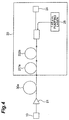
- Fig. 4 shows an embodiment of the combination of Raman amplification and the dispersion compensation in an optical transmission system.
- an optical fiber transmission line 30a is laid between a transmitter station (or repeater station) 10 and a receiver station (or repeater station) 20, and light signal sent from the transmitter station 10 is amplified in an optical amplifier 21 (EDFA) to transmitted to the dispersion compensator.
- EDFA optical amplifier
- a dispersion-compensating fibers 211a and 222a are connected in serial.
- An optical coupler is provided in an output of the dispersion-compensating fiber 222a, and the optical coupler is connected to a pumping light laser for generating an excitation light having a wavelength of 1.45 ⁇ m by which the Raman amplification is caused in the dispersion-compensating optical fibers 211a and 222a.
- An effective area of the dispersion-compensating optical fiber 211a is larger than that of the dispersion-compensating optical fiber 222a.
- the nonlinear optical phenomenon degrading the transmission quality of the optical transmission line is be more suppressed when the effective area Aeff of the optical fiber is larger, and the efficiency of the Raman amplification can be more improved when the effective area Aeff of the optical fiber is smaller.
- the signal light is guided to the output of the dispersion-compensating optical fiber 211a having a larger effective area Aeff, and the excitation light having the wavelength of 1.45 ⁇ m for Raman amplification is guided to an output of the dispersion-compensating optical fiber 222a having a smaller effective area Aeff.
- dispersion-compensating optical fibers 221 and 222 may be connected to each other by an optical connector, they are preferably connected by fusion splice, which yields a lower splice loss.
- fusion splice respective end portions of the dispersion-compensating optical fibers 221 and 222 are stripped of their coatings, and these respective end faces of the glass fibers are butted against each other and heated, so as to be fusion-spliced.
- the mechanical strength of the fusion-spliced portion is weak in this state. Therefore, it is preferred that the . dispersion-compensating optical fibers 221 and 222 be contained in the dispersion compensator 22 after their fusion-spliced portion is processed as follows.
- Figs. 5 and 6 are explanatory views of a first example of the mode of containing the dispersion compensator 22 in accordance with this embodiment.
- Fig. 5 is a sectional view thereof near a fusion-spliced portion 220
- Fig. 5 is a perspective view of the dispersion-compensating optical fibers 221 and 222 wound about a bobbin 223.
- a glass fiber 221a is stripped of its surrounding coating 221b at an end portion of the dispersion-compensating optical fiber 221.
- a glass fiber 222a is stripped of its surrounding coating 222b at an end portion of the dispersion-compensating optical fiber 222.
- the fusion-spliced portion 220 is wound about the bobbin 223 together with the dispersion-compensating optical fibers 221 and 222.
- the dispersion-compensating optical fibers 221 and 222 can be contained in a compact state while the resin material 224 imparts a mechanical strength to the fusion-spliced portion 220.
- the outside diameter of each of the dispersion-compensating optical fibers 221 and 222 is substantially equal to the outside diameter of the resin material 224, no stress applies to the dispersion-compensating optical fibers 221 and 222 due to uneven outside diameters, whereby the increase in loss can be suppressed.
- Figs. 7 and 8 are explanatory views of a second example of the mode of containing the dispersion compensator 22 in accordance with this embodiment.
- Fig. 7 is a sectional view thereof near the fusion-spliced portion 220
- Fig. 7 is a sectional view of the dispersion-compensating optical fibers 221 and 222 wound about the bobbin 223.
- the glass fiber 221a is stripped of its surrounding coating 221b at an end portion of the dispersion-compensating optical fiber 221.
- the glass fiber 222a is stripped of its surrounding coating 222b at an end portion of the dispersion-compensating optical fiber 222.
- fusion-spliced portions 220 are fusion-spliced to each other.
- the surroundings of thus formed fusion-spliced portion (the part stripped of the coating) 220 between the dispersion-compensating optical fibers 221 and 222 are re-coated with a resin material 224.
- the fusion-spliced portion 220 is further provided with a metal bar 225 acting as reinforcement means, and is contained in a shrink tube 226 together with the metal bar 225.
- the fusion-spliced portion 220 is wound about the bobbin 223 together with the dispersion-compensating optical fibers 221 and 222.
- the fusion-spliced portion 220 provided with the metal bar 225 is secured to a certain part of the bobbin 223 (e.g., the inner or outer face of a flange thereof) .
- the dispersion-compensating optical fibers 221 and 222 can be contained in a compact state while the metal bar 225 imparts a mechanical strength to the fusion-spliced portion 220.
- the reliability of the fusion-spliced portion 220 is high since it is provided with the metal bar 225 acting as reinforcement means.
- Fig. 9 is an explanatory view of a third example of the mode of containing the dispersion compensator 22 in accordance with this embodiment.
- the dispersion-compensating optical fibers 221 and 222 are contained in a bundle state as shown in Fig. 8 without being wound about a bobbin.
- the dispersion-compensating optical fibers 221 and 222 can be contained in a compact state while a mechanical strength is imparted to the fusion-spliced portion 220.
- each of the dispersion-compensating optical fibers 221 and 222 is substantially equal to the outside diameter of the resin material 224, no stress applies to the dispersion-compensating optical fibers 221 and 222 due to uneven outside diameters, whereby the increase in loss can be suppressed.
- dispersion-compensating optical fibers 221 and 222 are not wound about a bobbin but contained in a bundle state free of any body portion substantially in contact therewith, no stress applies thereto from the barrel portion of the bobbin, whereby the increase in loss can be suppressed in each dispersion-compensating optical fiber having a sensitive microbend loss characteristic.
- the dispersion-compensating optical fibers 221 and 222 in a bundle state are filled with a resin material.
- dispersion-compensating optical fibers 221 and 222 are wound like a coil as shown in each of Figs. 6, 8, and 9, it is preferred that, of the dispersion-compensating optical fibers 221 and 222, one with the higher dispersion slope compensation ratio ⁇ have the larger winding diameter.
- dispersion-compensating optical fibers yield a greater bending loss as their dispersion slope compensation ratio ⁇ is higher. Therefore, when the bending diameter of dispersion-compensating optical fibers is thus made larger as the dispersion slope compensation ratio ⁇ is higher, the increase in loss caused by winding the dispersion-compensating optical fibers 221 and 222 like a coil can be suppressed.
- the respective surfaces of the glass fibers 221a and 222a of the dispersion-compensating optical fibers 221 and 222 are provided with hermetic coatings made of a carbon material or the like.
- the dispersion-compensating optical fibers 221, 222 improve their fatigue resistance characteristics with respect to the state where they are contained as being wound like a coil at a small bending diameter.
- the hydrogen gas generated from the surrounding coating material can be prevented from entering the glass fibers 221a, 221b, whereby transmission loss can be kept from increasing.
- the present invention can be modified in various manners. While the dispersion compensator is constituted by two dispersion-compensating optical fibers connected to each other in the above-mentioned embodiments, three or more dispersion-compensating optical fibers may be connected so as to construct the dispersion compensator.
- each of the N dispersion-compensating optical fibers has a dispersion slope compensation ratio of at least 60%
- one of the N dispersion-compensating optical fibers has a dispersion slope compensation ratio of at least 80%
- another of the dispersion-compensating optical fibers has a dispersion slope compensation ratio within the range of 60% to 100%.
- the N dispersion-compensating optical fibers in total have an average dispersion slope compensation ratio of at least 80% but not greater than 120%. It is also preferred that the N dispersion-compensating optical fibers be connected in the order of increasing effective area thereof.
- an optical transmission line is explained as a single mode fiber (SMF) having a zero chromatic dispersion at the wavelength in 1.3 ⁇ m band
- the dispersion compensator and optical transmission system of the present invention can be applied to all of optical fibers having an anormalous dispersion at the wavelength in 1.55 ⁇ m band also.
- D SMF and "S SMF” in the above equations should be read as the corresponding characteristics of such optical fiber.
- the above optical fiber of 1.55 ⁇ m band may be referred as a none-zero dispersion shifted fiber (NZ-DSF) of which the dispersion at the wavelength in 1.55 ⁇ m band is + 2 ps/km/nm to +10 ps/km/nm, hthe dispersion slope is from +0.03 ps/km/nm 2 to +0.1 ps/km/nm 2 .
- NZ-DSF none-zero dispersion shifted fiber
- the wavelength of signal light used therein is referred as the wavelength of 1.55 ⁇ m band
- the dispersion compensator and the optical transmission system according to the present invention can be applied to the signal light having the wavelength of 1600 nm band (L-band) or the wavelength of 1.45 ⁇ m band (S-band) also.
- the above stated advantages obtained in the present invention can be obtained in the transmission optical line having an anormalous dispersion at the wavelength at the each of the above stated wavelength bands also.
- the dispersion compensator in accordance with the present invention is a dispersion compensator for compensation for the chromatic dispersion and dispersion slope of an optical fiber transmission line, in which a plurality of dispersion-compensating optical fibers each having a dispersion slope compensation ratio of at least 60% are connected to each other, one of the plurality of dispersion-compensating optical fibers has a dispersion slope compensation ratio of at least 80%, and another of the plurality of dispersion-compensating optical fibers has a dispersion slope compensation ratio within the range of 60% to 100%.
- the average dispersion slope compensation ratio of the dispersion compensator can attain a value near 100%.
- the dispersion compensator can fully compensate for both the chromatic dispersion and dispersion slope of the optical fiber transmission line if the respective lengths of the plurality of dispersion-compensating optical fibers are appropriately set according to the length of the optical fiber transmission line.
- the dispersion slope compensation ratio ⁇ of each dispersion-compensating optical fiber is measured after manufacture, and a plurality of dispersion-compensating optical fibers are connected according to results of the measurement so as to construct the dispersion compensator as mentioned above.
- the manufactured dispersion-compensating optical fibers can be used efficiently, whereby the dispersion compensator becomes inexpensive.
- the dispersion compensator can fully compensate for both the chromatic dispersion and dispersion slope of the optical fiber transmission line.
- the plurality of dispersion-compensating optical fibers are connected in the order of increasing effective area thereof, signal light having a higher power propagates through a dispersion-compensating optical fiber having a relatively larger effective area, so that the occurrence of nonlinear optical phenomena can be suppressed, whereby transmission characteristics become excellent.
- first and second dispersion-compensating optical fibers cascaded to each other are fusion-spliced to each other, the splice loss between the first and second dispersion-compensating optical fibers is low.
- the fusion-spliced portion between the first and second dispersion-compensating optical fibers be re-coated with a resin material having a coating diameter substantially equal to the coating diameter of each of the first and second dispersion-compensating optical fibers, and be wound about a bobbin together with the first and second dispersion-compensating optical fibers.
- the fusion-spliced portion between the first and second dispersion-compensating optical fibers be re-coated with a resin material and be secured with reinforcement means. It is also preferred that the plurality of dispersion-compensating optical fibers be contained in a bundle state free of any body portion substantially in contact therewith. In any of these cases, each of the plurality of dispersion-compensating optical fibers can be contained in a compact state while securing a mechanical strength in the fusion-spliced portion and suppressing the increase in transmission loss.
- the dispersion compensator compensates for the chromatic dispersion and dispersion slope of the optical fiber transmission line, whereby both the respective absolute values of the average chromatic dispersion and average dispersion slope of the optical fiber transmission line and dispersion compensator are reduced.
- this optical transmission system can carry out WDM transmission over a wide band and optical transmission with a high bit rate.
- the plurality of dispersion-compensating optical fibers in the dispersion compensator are connected in the order of increasing effective area thereof, while signal light is fed from the side of the dispersion-compensating optical fiber having the larger effective area, the occurrence of nonlinear optical phenomena can be suppressed in the dispersion compensator, whereby transmission characteristics become excellent.
Landscapes
- Physics & Mathematics (AREA)
- Engineering & Computer Science (AREA)
- Chemical & Material Sciences (AREA)
- Dispersion Chemistry (AREA)
- General Physics & Mathematics (AREA)
- Optics & Photonics (AREA)
- Electromagnetism (AREA)
- Computer Networks & Wireless Communication (AREA)
- Signal Processing (AREA)
- Microelectronics & Electronic Packaging (AREA)
- Optical Communication System (AREA)
- Optical Fibers, Optical Fiber Cores, And Optical Fiber Bundles (AREA)
Abstract
Description

Claims (12)
- A dispersion compensator for compensating for a chromatic dispersion and dispersion slope of an optical fiber transmission line;
said dispersion compensator comprising a plurality of dispersion-compensating optical fibers connected to each other, said dispersion-compensating optical fibers each having a dispersion slope compensation ratio of at least 60% with respect to said optical fiber transmission line at a predetermined wavelength;
one of said plurality of dispersion-compensating optical fibers having a dispersion slope compensation ratio of at least 80%;
another of said plurality of dispersion-compensating optical fibers having a dispersion slope compensation ratio within the range of 60% to 100%. - A dispersion compensator according to claim 1, wherein said plurality of dispersion-compensating optical fibers in total have an average dispersion slope compensation ratio of at least 80%.
- A dispersion compensator according to claim 1, wherein said plurality of dispersion-compensating optical fibers are connected in the order of increasing effective area thereof.
- A dispersion compensator according to claim 1, wherein, of said plurality of dispersion-compensating optical fibers, first and second dispersion-compensating optical fibers cascaded to each other are fusion-spliced.
- A dispersion compensator according to claim 4, wherein the fusion-spliced portion between said first and second dispersion-compensating optical fibers is re-coated with a resin material having a coating diameter substantially equal to the coating diameter of each of said first and second dispersion-compensating optical fibers, and is wound on a bobbin together with said first and second dispersion-compensating optical fibers.
- A dispersion compensator according to claim 4, wherein the fusion-spliced portion between said first and second dispersion-compensating optical fibers is re-coated with a resin material and is secured with reinforcement means.
- A dispersion compensator according to claim 4, wherein said plurality of dispersion-compensating optical fibers are contained in a bundle state free of any body portion substantially in contact therewith.
- A dispersion compensator according to claim 3, wherein said plurality of dispersion-compensating optical fibers are connected in the order of increasing dispersion compensation ratios thereof.
- A dispersion compensator according to claim 3, wherein said plurality of dispersion-compensating optical fibers are connected in the order of increasing dispersion compensation ratios thereof, and a signal light is input to an input end of said dispersion-compensating fiber of said plurality of dispersion-compensating fibers, having a larger effective area and smaller dispersion slope compensation ratio.
- An optical transmission system comprising:an optical fiber transmission line for transmitting signal light; andthe dispersion compensator of claim 1, comprising a plurality of dispersion-compensating optical fibers connected to each other, for compensating for the chromatic dispersion and dispersion slope of said optical fiber transmission line.
- An optical transmission system according to claim 8, wherein said plurality of dispersion-compensating optical fibers are connected in the order of increasing effective area thereof, and signal light is fed from the side of the dispersion-compensating optical fiber having a larger effective area.
- An optical transmission system according to claim 10, wherein said plurality of dispersion-compensating optical fibers are connected in the order of increasing dispersion compensation ratios thereof, and a signal light is input to an input end of said dispersion-compensating fiber of said plurality of dispersion-compensating fibers, having a larger effective area, and an exciting light for causing Raman amplification is input to an input end of said dispersion-compensating fiber of said plurality of dispersion-compensating fibers, having a smaller effective area.
Applications Claiming Priority (3)
| Application Number | Priority Date | Filing Date | Title |
|---|---|---|---|
| JP2000068966A JP4362927B2 (en) | 2000-03-13 | 2000-03-13 | Dispersion compensator and optical transmission system |
| JP2000068966 | 2000-03-13 | ||
| PCT/JP2001/001968 WO2001069822A1 (en) | 2000-03-13 | 2001-03-13 | Dispersion compensator |
Publications (3)
| Publication Number | Publication Date |
|---|---|
| EP1278316A1 true EP1278316A1 (en) | 2003-01-22 |
| EP1278316A4 EP1278316A4 (en) | 2006-11-22 |
| EP1278316B1 EP1278316B1 (en) | 2008-09-24 |
Family
ID=18587936
Family Applications (1)
| Application Number | Title | Priority Date | Filing Date |
|---|---|---|---|
| EP01912318A Expired - Lifetime EP1278316B1 (en) | 2000-03-13 | 2001-03-13 | Dispersion compensator |
Country Status (10)
| Country | Link |
|---|---|
| EP (1) | EP1278316B1 (en) |
| JP (1) | JP4362927B2 (en) |
| KR (1) | KR100589301B1 (en) |
| CN (2) | CN1222125C (en) |
| AU (2) | AU2001241119B2 (en) |
| CA (1) | CA2403206A1 (en) |
| DE (1) | DE60135909D1 (en) |
| IL (1) | IL151735A0 (en) |
| TW (1) | TW498635B (en) |
| WO (1) | WO2001069822A1 (en) |
Cited By (1)
| Publication number | Priority date | Publication date | Assignee | Title |
|---|---|---|---|---|
| EP1919106A1 (en) | 2006-11-03 | 2008-05-07 | Draka comteq B.V. | Chromatic dispersion compensating fiber |
Families Citing this family (8)
| Publication number | Priority date | Publication date | Assignee | Title |
|---|---|---|---|---|
| JP2001296444A (en) * | 2000-04-11 | 2001-10-26 | Sumitomo Electric Ind Ltd | Dispersion compensating optical fiber, optical transmission line and dispersion compensating module |
| US6724956B2 (en) | 2002-04-03 | 2004-04-20 | Fitel Usa Corporation | Method and apparatus for providing dispersion compensation |
| FR2842676B1 (en) * | 2002-07-18 | 2007-07-20 | Cit Alcatel | METHOD FOR MAKING AND IMPROVING AN OPTICAL TRANSMISSION LINE AND ASSOCIATED COMPENSATION MODULES |
| US6707976B1 (en) | 2002-09-04 | 2004-03-16 | Fitel Usa Corporation | Inverse dispersion compensating fiber |
| JP4626127B2 (en) * | 2003-04-09 | 2011-02-02 | 住友電気工業株式会社 | Optical transmission line configuration method |
| US20110318019A1 (en) * | 2010-06-29 | 2011-12-29 | Tyco Electronics Subsea Communication LLC | Communication transmission system with optically aided digital signal processing dispersion compensation |
| CN110061780B (en) * | 2018-01-19 | 2022-04-12 | 华为技术有限公司 | Dispersion compensation method and device |
| CN112913541A (en) * | 2021-01-11 | 2021-06-08 | 刘德仁 | Deinsectization method for cultivating excellent new variety of agricultural and forestry plants |
Family Cites Families (10)
| Publication number | Priority date | Publication date | Assignee | Title |
|---|---|---|---|---|
| US5042906A (en) * | 1990-07-05 | 1991-08-27 | Hughes Aircraft Company | Dispersion equalized optical fiber link |
| JP2988571B2 (en) * | 1995-03-10 | 1999-12-13 | 古河電気工業株式会社 | Dispersion compensating optical fiber |
| CA2170815C (en) * | 1995-03-10 | 2002-05-28 | Youichi Akasaka | Dispersion compensating optical fiber |
| JPH1073738A (en) * | 1996-06-21 | 1998-03-17 | Furukawa Electric Co Ltd:The | WDM communication link for optical transmission |
| JPH10325913A (en) * | 1997-03-25 | 1998-12-08 | Furukawa Electric Co Ltd:The | Dispersion compensating optical fiber and WDM optical transmission line using the optical fiber |
| JPH10303489A (en) * | 1997-04-23 | 1998-11-13 | Kyocera Corp | Optical fiber amplifier |
| JP3418086B2 (en) * | 1997-05-09 | 2003-06-16 | 住友電気工業株式会社 | Optical transmission line for wavelength division multiplexing transmission and method of configuring the same |
| US5887093A (en) * | 1997-09-12 | 1999-03-23 | Lucent Technologies Incorporated | Optical fiber dispersion compensation |
| JPH11295079A (en) * | 1998-04-08 | 1999-10-29 | Tamagawa Seiki Co Ltd | Optical fiber coil for detector and manufacturing method thereof |
| JP2000072329A (en) * | 1998-09-02 | 2000-03-07 | Fujikura Ltd | A bobbin such as an optical fiber and a method of winding an optical fiber around the bobbin |
-
2000
- 2000-03-13 JP JP2000068966A patent/JP4362927B2/en not_active Expired - Fee Related
-
2001
- 2001-03-13 DE DE60135909T patent/DE60135909D1/en not_active Expired - Lifetime
- 2001-03-13 CA CA002403206A patent/CA2403206A1/en not_active Abandoned
- 2001-03-13 EP EP01912318A patent/EP1278316B1/en not_active Expired - Lifetime
- 2001-03-13 WO PCT/JP2001/001968 patent/WO2001069822A1/en not_active Ceased
- 2001-03-13 IL IL15173501A patent/IL151735A0/en unknown
- 2001-03-13 CN CNB018049591A patent/CN1222125C/en not_active Expired - Fee Related
- 2001-03-13 AU AU2001241119A patent/AU2001241119B2/en not_active Ceased
- 2001-03-13 TW TW090105834A patent/TW498635B/en not_active IP Right Cessation
- 2001-03-13 AU AU4111901A patent/AU4111901A/en active Pending
- 2001-03-13 CN CNB2005100517837A patent/CN100347974C/en not_active Expired - Fee Related
- 2001-03-13 KR KR1020027011908A patent/KR100589301B1/en not_active Expired - Fee Related
Cited By (2)
| Publication number | Priority date | Publication date | Assignee | Title |
|---|---|---|---|---|
| EP1919106A1 (en) | 2006-11-03 | 2008-05-07 | Draka comteq B.V. | Chromatic dispersion compensating fiber |
| US7483613B2 (en) | 2006-11-03 | 2009-01-27 | Draka Comteq B.V. | Chromatic dispersion compensating fiber |
Also Published As
| Publication number | Publication date |
|---|---|
| JP4362927B2 (en) | 2009-11-11 |
| CN100347974C (en) | 2007-11-07 |
| IL151735A0 (en) | 2003-04-10 |
| EP1278316A4 (en) | 2006-11-22 |
| KR100589301B1 (en) | 2006-06-14 |
| KR20020084178A (en) | 2002-11-04 |
| AU4111901A (en) | 2001-09-24 |
| AU2001241119B2 (en) | 2004-09-16 |
| WO2001069822A1 (en) | 2001-09-20 |
| TW498635B (en) | 2002-08-11 |
| CA2403206A1 (en) | 2001-09-20 |
| CN1401165A (en) | 2003-03-05 |
| JP2001257643A (en) | 2001-09-21 |
| CN1667983A (en) | 2005-09-14 |
| CN1222125C (en) | 2005-10-05 |
| DE60135909D1 (en) | 2008-11-06 |
| EP1278316B1 (en) | 2008-09-24 |
Similar Documents
| Publication | Publication Date | Title |
|---|---|---|
| US6628872B2 (en) | Dispersion compensator and optical transmission system | |
| EP1170604A2 (en) | Optical fiber, optical transmission line and dispersion compensating module | |
| US6477306B2 (en) | Dispersion-compensating optical fiber, and, optical transmission line and dispersion-compensating module respectively including the same | |
| EP1130428A1 (en) | Dispersion compensating fiber | |
| EP2362252A1 (en) | Optical fiber and optical communication system including same | |
| US6400877B1 (en) | Negative-dispersion optical fiber and optical transmission line incorporating the same | |
| JPWO2000017685A1 (en) | Dispersion Compensating Fiber | |
| US6862391B2 (en) | Optical transmission line, and optical fiber and dispersion compensating module employed in the same | |
| EP1396743A2 (en) | Dispersion compensating optical fiber | |
| EP1164412B1 (en) | Optical transimission line enabling Raman amplification and optical transmission system | |
| EP1278316B1 (en) | Dispersion compensator | |
| US6791744B2 (en) | Raman amplification optical fiber, optical fiber coil, raman amplifier, and optical communication system | |
| EP1202479A1 (en) | Dispersion compensation system | |
| US6724964B2 (en) | Optical waveguide exhibiting strongly positive dispersion, and system utilizing same | |
| US6771864B2 (en) | Optical fiber transmission line, optical cable, and optical transmission system | |
| US7016581B2 (en) | Dispersion compensation unit and optical communication system | |
| US6907172B2 (en) | Optical transmission line and optical communication system | |
| JP2001264569A (en) | Dispersion compensating optical fiber and optical transmission system | |
| US20030156809A1 (en) | Dispersion compensating optical fiber, dispersion compensating device, optical transmission line and optical transmission system | |
| US6898361B2 (en) | Dispersion-compensating optical fiber and optical transmission line | |
| US20030169986A1 (en) | Optical fiber, optical component, dispersion compensating fiber module, and optical communication system | |
| US20030108313A1 (en) | Optical fiber transmission line, optical cable, and optical transmission system | |
| JP2003084162A (en) | Negative dispersion optical fiber, optical amplifier and optical transmission line | |
| JP2002062452A (en) | Negative dispersion optical fiber and optical transmission line | |
| EP1372279A2 (en) | Dispersion compensation unit and optical communication system |
Legal Events
| Date | Code | Title | Description |
|---|---|---|---|
| PUAI | Public reference made under article 153(3) epc to a published international application that has entered the european phase |
Free format text: ORIGINAL CODE: 0009012 |
|
| 17P | Request for examination filed |
Effective date: 20021010 |
|
| AK | Designated contracting states |
Kind code of ref document: A1 Designated state(s): AT BE CH CY DE DK ES FI FR GB GR IE IT LI LU MC NL PT SE TR |
|
| RBV | Designated contracting states (corrected) |
Designated state(s): DE DK FR GB IT SE |
|
| A4 | Supplementary search report drawn up and despatched |
Effective date: 20061023 |
|
| 17Q | First examination report despatched |
Effective date: 20061120 |
|
| GRAP | Despatch of communication of intention to grant a patent |
Free format text: ORIGINAL CODE: EPIDOSNIGR1 |
|
| GRAS | Grant fee paid |
Free format text: ORIGINAL CODE: EPIDOSNIGR3 |
|
| GRAA | (expected) grant |
Free format text: ORIGINAL CODE: 0009210 |
|
| AK | Designated contracting states |
Kind code of ref document: B1 Designated state(s): DE DK FR GB IT SE |
|
| REG | Reference to a national code |
Ref country code: GB Ref legal event code: FG4D |
|
| REF | Corresponds to: |
Ref document number: 60135909 Country of ref document: DE Date of ref document: 20081106 Kind code of ref document: P |
|
| PG25 | Lapsed in a contracting state [announced via postgrant information from national office to epo] |
Ref country code: DK Free format text: LAPSE BECAUSE OF FAILURE TO SUBMIT A TRANSLATION OF THE DESCRIPTION OR TO PAY THE FEE WITHIN THE PRESCRIBED TIME-LIMIT Effective date: 20080924 |
|
| PLBE | No opposition filed within time limit |
Free format text: ORIGINAL CODE: 0009261 |
|
| STAA | Information on the status of an ep patent application or granted ep patent |
Free format text: STATUS: NO OPPOSITION FILED WITHIN TIME LIMIT |
|
| PG25 | Lapsed in a contracting state [announced via postgrant information from national office to epo] |
Ref country code: IT Free format text: LAPSE BECAUSE OF FAILURE TO SUBMIT A TRANSLATION OF THE DESCRIPTION OR TO PAY THE FEE WITHIN THE PRESCRIBED TIME-LIMIT Effective date: 20080924 |
|
| 26N | No opposition filed |
Effective date: 20090625 |
|
| GBPC | Gb: european patent ceased through non-payment of renewal fee |
Effective date: 20090313 |
|
| PG25 | Lapsed in a contracting state [announced via postgrant information from national office to epo] |
Ref country code: SE Free format text: LAPSE BECAUSE OF FAILURE TO SUBMIT A TRANSLATION OF THE DESCRIPTION OR TO PAY THE FEE WITHIN THE PRESCRIBED TIME-LIMIT Effective date: 20081224 |
|
| PG25 | Lapsed in a contracting state [announced via postgrant information from national office to epo] |
Ref country code: GB Free format text: LAPSE BECAUSE OF NON-PAYMENT OF DUE FEES Effective date: 20090313 |
|
| PGFP | Annual fee paid to national office [announced via postgrant information from national office to epo] |
Ref country code: FR Payment date: 20120319 Year of fee payment: 12 |
|
| PGFP | Annual fee paid to national office [announced via postgrant information from national office to epo] |
Ref country code: DE Payment date: 20120411 Year of fee payment: 12 |
|
| REG | Reference to a national code |
Ref country code: FR Ref legal event code: ST Effective date: 20131129 |
|
| REG | Reference to a national code |
Ref country code: DE Ref legal event code: R119 Ref document number: 60135909 Country of ref document: DE Effective date: 20131001 |
|
| PG25 | Lapsed in a contracting state [announced via postgrant information from national office to epo] |
Ref country code: FR Free format text: LAPSE BECAUSE OF NON-PAYMENT OF DUE FEES Effective date: 20130402 Ref country code: DE Free format text: LAPSE BECAUSE OF NON-PAYMENT OF DUE FEES Effective date: 20131001 |