EP1278315A1 - Gain equalisation in an optical transmission system - Google Patents
Gain equalisation in an optical transmission system Download PDFInfo
- Publication number
- EP1278315A1 EP1278315A1 EP01401963A EP01401963A EP1278315A1 EP 1278315 A1 EP1278315 A1 EP 1278315A1 EP 01401963 A EP01401963 A EP 01401963A EP 01401963 A EP01401963 A EP 01401963A EP 1278315 A1 EP1278315 A1 EP 1278315A1
- Authority
- EP
- European Patent Office
- Prior art keywords
- gain
- stage
- optical
- fiber
- inter
- Prior art date
- Legal status (The legal status is an assumption and is not a legal conclusion. Google has not performed a legal analysis and makes no representation as to the accuracy of the status listed.)
- Granted
Links
Images

Classifications
-
- H—ELECTRICITY
- H04—ELECTRIC COMMUNICATION TECHNIQUE
- H04B—TRANSMISSION
- H04B10/00—Transmission systems employing electromagnetic waves other than radio-waves, e.g. infrared, visible or ultraviolet light, or employing corpuscular radiation, e.g. quantum communication
- H04B10/29—Repeaters
- H04B10/291—Repeaters in which processing or amplification is carried out without conversion of the main signal from optical form
- H04B10/293—Signal power control
- H04B10/294—Signal power control in a multiwavelength system, e.g. gain equalisation
- H04B10/2941—Signal power control in a multiwavelength system, e.g. gain equalisation using an equalising unit, e.g. a filter
-
- H—ELECTRICITY
- H01—ELECTRIC ELEMENTS
- H01S—DEVICES USING THE PROCESS OF LIGHT AMPLIFICATION BY STIMULATED EMISSION OF RADIATION [LASER] TO AMPLIFY OR GENERATE LIGHT; DEVICES USING STIMULATED EMISSION OF ELECTROMAGNETIC RADIATION IN WAVE RANGES OTHER THAN OPTICAL
- H01S3/00—Lasers, i.e. devices using stimulated emission of electromagnetic radiation in the infrared, visible or ultraviolet wave range
- H01S3/05—Construction or shape of optical resonators; Accommodation of active medium therein; Shape of active medium
- H01S3/06—Construction or shape of active medium
- H01S3/063—Waveguide lasers, i.e. whereby the dimensions of the waveguide are of the order of the light wavelength
- H01S3/067—Fibre lasers
- H01S3/06754—Fibre amplifiers
-
- H—ELECTRICITY
- H04—ELECTRIC COMMUNICATION TECHNIQUE
- H04B—TRANSMISSION
- H04B10/00—Transmission systems employing electromagnetic waves other than radio-waves, e.g. infrared, visible or ultraviolet light, or employing corpuscular radiation, e.g. quantum communication
- H04B10/29—Repeaters
- H04B10/291—Repeaters in which processing or amplification is carried out without conversion of the main signal from optical form
- H04B10/2912—Repeaters in which processing or amplification is carried out without conversion of the main signal from optical form characterised by the medium used for amplification or processing
- H04B10/2916—Repeaters in which processing or amplification is carried out without conversion of the main signal from optical form characterised by the medium used for amplification or processing using Raman or Brillouin amplifiers
-
- H—ELECTRICITY
- H04—ELECTRIC COMMUNICATION TECHNIQUE
- H04B—TRANSMISSION
- H04B10/00—Transmission systems employing electromagnetic waves other than radio-waves, e.g. infrared, visible or ultraviolet light, or employing corpuscular radiation, e.g. quantum communication
- H04B10/29—Repeaters
- H04B10/291—Repeaters in which processing or amplification is carried out without conversion of the main signal from optical form
- H04B10/293—Signal power control
- H04B10/294—Signal power control in a multiwavelength system, e.g. gain equalisation
- H04B10/2942—Signal power control in a multiwavelength system, e.g. gain equalisation using automatic gain control [AGC]
-
- H—ELECTRICITY
- H04—ELECTRIC COMMUNICATION TECHNIQUE
- H04J—MULTIPLEX COMMUNICATION
- H04J14/00—Optical multiplex systems
- H04J14/02—Wavelength-division multiplex systems
- H04J14/0221—Power control, e.g. to keep the total optical power constant
- H04J14/02216—Power control, e.g. to keep the total optical power constant by gain equalization
-
- H—ELECTRICITY
- H01—ELECTRIC ELEMENTS
- H01S—DEVICES USING THE PROCESS OF LIGHT AMPLIFICATION BY STIMULATED EMISSION OF RADIATION [LASER] TO AMPLIFY OR GENERATE LIGHT; DEVICES USING STIMULATED EMISSION OF ELECTROMAGNETIC RADIATION IN WAVE RANGES OTHER THAN OPTICAL
- H01S2301/00—Functional characteristics
- H01S2301/04—Gain spectral shaping, flattening
-
- H—ELECTRICITY
- H01—ELECTRIC ELEMENTS
- H01S—DEVICES USING THE PROCESS OF LIGHT AMPLIFICATION BY STIMULATED EMISSION OF RADIATION [LASER] TO AMPLIFY OR GENERATE LIGHT; DEVICES USING STIMULATED EMISSION OF ELECTROMAGNETIC RADIATION IN WAVE RANGES OTHER THAN OPTICAL
- H01S3/00—Lasers, i.e. devices using stimulated emission of electromagnetic radiation in the infrared, visible or ultraviolet wave range
- H01S3/005—Optical devices external to the laser cavity, specially adapted for lasers, e.g. for homogenisation of the beam or for manipulating laser pulses, e.g. pulse shaping
- H01S3/0057—Temporal shaping, e.g. pulse compression, frequency chirping
-
- H—ELECTRICITY
- H01—ELECTRIC ELEMENTS
- H01S—DEVICES USING THE PROCESS OF LIGHT AMPLIFICATION BY STIMULATED EMISSION OF RADIATION [LASER] TO AMPLIFY OR GENERATE LIGHT; DEVICES USING STIMULATED EMISSION OF ELECTROMAGNETIC RADIATION IN WAVE RANGES OTHER THAN OPTICAL
- H01S3/00—Lasers, i.e. devices using stimulated emission of electromagnetic radiation in the infrared, visible or ultraviolet wave range
- H01S3/14—Lasers, i.e. devices using stimulated emission of electromagnetic radiation in the infrared, visible or ultraviolet wave range characterised by the material used as the active medium
- H01S3/16—Solid materials
- H01S3/1601—Solid materials characterised by an active (lasing) ion
- H01S3/1603—Solid materials characterised by an active (lasing) ion rare earth
- H01S3/1608—Solid materials characterised by an active (lasing) ion rare earth erbium
-
- H—ELECTRICITY
- H01—ELECTRIC ELEMENTS
- H01S—DEVICES USING THE PROCESS OF LIGHT AMPLIFICATION BY STIMULATED EMISSION OF RADIATION [LASER] TO AMPLIFY OR GENERATE LIGHT; DEVICES USING STIMULATED EMISSION OF ELECTROMAGNETIC RADIATION IN WAVE RANGES OTHER THAN OPTICAL
- H01S3/00—Lasers, i.e. devices using stimulated emission of electromagnetic radiation in the infrared, visible or ultraviolet wave range
- H01S3/30—Lasers, i.e. devices using stimulated emission of electromagnetic radiation in the infrared, visible or ultraviolet wave range using scattering effects, e.g. stimulated Brillouin or Raman effects
- H01S3/302—Lasers, i.e. devices using stimulated emission of electromagnetic radiation in the infrared, visible or ultraviolet wave range using scattering effects, e.g. stimulated Brillouin or Raman effects in an optical fibre
Definitions
- the invention relates to the field of optical communication technology. More particularly the invention relates to gain equalization in optical transmission systems.
- WDM Wavelength division multiplexing
- a problem of such optically amplified transmission systems is that in each section of such systems extra losses can be induced due to ageing of components. In particular ageing of transmission fiber can lead to significant line losses. Such losses can be compensated by in-line optical amplification, e.g. using erbium doped fiber amplifiers (EDFA).
- EDFA erbium doped fiber amplifiers
- the optical amplifier gain is increased according to the extra losses of the section. This extra amplifier gain however induces a strong gain distortion of the EDFA over the wavelength range. This gain distortion is in fact linear in dB versus wavelength and is about 0.2 dB per amplifier over 12 nm for a 1 dB gain change.
- This gain distortion induces a degradation of the transmission that can be drastic for very long haul systems, e.g. for systems comprising more than one hundred repeaters.
- Another problem of state-of-the-art optical transmission systems is the fact that the loss of a fiber span is not exactly known when cable and repeaters are assembled.
- an EDFA is designed in function of it's nominal expected gain. This nominal gain is calculated with an assumption of the span loss of the fiber cable, which is manufactured in parallel with the EDFAs.
- the real gain of the EDFAs can be lower or higher than the expected one, thus inducing a linear tilt in dB versus wavelength. This tilt is negative or positive, depending on whether the EDFA gain is higher or lower than the gain used to design the EDFA. Therefore, the optimization of the overall link can be carried out only after the assembly of the cable and the repeaters, that is iust before the laying, and thus too late to introduce adapted gain flattening filters.
- EDFAs are composed of two stages and allow a mid-stage access. This mid-stage access is often used for inserting a Dispersion Compensating Fiber (DCF) to compensate for chromatic dispersion accumulated along the previous section.
- DCF Dispersion Compensating Fiber
- These amplifiers are designed to have a flat spectral gain in dB for a certain gain and a certain mid-stage. But in the real system, those amplifiers are rarely used at their nominal functional point and the gain is never flat. A further problem is therefore to find a way to compensate for this unflatness.
- the disadvantages of this solution are the following:
- the Raman gain is not linear in dB versus wavelength over 25 nm (1535-1560 nm) for a pumping wavelength of 1430 nm. Therefore the gain equalization cannot be carried out on a wide optical bandwidth, but is limited to only 15 nm.
- a system for gain equalization in an optical communication system is provided.
- the optical communication system comprises a fiber link with a two-stage EDFA with an inter-stage access, and in the inter-stage:
- the Raman pump is adapted to provide a first gain slope with an opposite trend with respect to the filter and VOA, and is further adapted such that the pump power can be controlled so as to modify the gain slope.
- the method comprises the steps of:
- the EDFA gain can be maintained flat for a desirable range of input power.
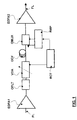
- FIG.1 A preferred embodiment of the present invention is shown in FIG.1.
- a double stage EDFA amplifier is provided, EDFA1 and EDFA2 with inter-stage access possibility, e.g. to compensate losses in the fiber link FL.
- an EDFA with standard configuration comprising a piece of Erbium doped fiber pumped by a semiconductor laser with a preferred wavelength at 1480 nm (to have a good power level) or 980 nm (to have a good noise figure) is used.
- the light of this pump is launched into the fiber through an optical multiplexer which also feeds the amplified signal at 1555 nm to the fiber.
- a Raman pump RMP is provided.
- the wavelength of the Raman pump is selected in accordance with the specific characteristics and operating requirements of the transmission system.
- a pump source wavelength of 1462 nm is employed, since it provides maximum gain over the wavelength range.
- the Raman pump RMP preferably employs a standard semiconductor laser as used in the EDFA with a wavelength at 1462 nm.
- the Raman pump is controlled from a remote control RCT, e.g. a terminal station.
- the Raman pump RMP is connected to the fiber DCF via an optical multiplexer OMUX, wherein the modulated channels are time division multiplexed and launched onto the fiber DCF.
- a known fiber fused multiplexer or multiplexer which use the bulk optics technology are employed.
- a fixed filter with linear negative slope over a wide spectral range is preferred.
- any fixed opticallinear filter can be used.
- VOA Variable Optical Attenuator
- the VOA attenuation is controlled from the remote control RCT.
- Preferred indicative values for VOA attenuation range typically between 2 and 8 dB.
- the slope of the Raman gain can be tuned by changing the power of Raman pump RMP.
- the whole When combined with the filter OFLT and variable attenuator VOA with negative slope, the whole provides the functionality of a tunable linear filter.
- the Raman gain shape is opposite to the filter response. Therefore, increasing the pump power induces a positive tilt and reducing the pump power induces a negative tilt.
- This functionality is independent of the EDFA characteristics and can be controlled remotely.
- the potential achievable slopes are shown in fig. 2. That means that the EDFA gain can be kept flat for a range of input power of about 7dB.
- the tilt can be compensated in a range between -2 and +2 dB, and the total noise figure is improved by 0.8 dB. Therefore the maximum link distance can be increased by typically 20%.
- changing the pump power induces a change of the input power of the EDFA following the Raman gain stage. This in turn induces a gain tilt of this EDFA with the same slope as the Raman gain tilt.
Landscapes
- Engineering & Computer Science (AREA)
- Physics & Mathematics (AREA)
- Electromagnetism (AREA)
- Computer Networks & Wireless Communication (AREA)
- Signal Processing (AREA)
- Plasma & Fusion (AREA)
- Optics & Photonics (AREA)
- Optical Communication System (AREA)
- Optical Modulation, Optical Deflection, Nonlinear Optics, Optical Demodulation, Optical Logic Elements (AREA)
- Lasers (AREA)
Abstract
Description
- The invention relates to the field of optical communication technology. More particularly the invention relates to gain equalization in optical transmission systems.
- In recent years, optically amplified transmission systems have been developed, in which digital data are transmitted by performing optical amplification and optical relay or repeat using optical transmission fiber. Wavelength division multiplexing (WDM) is used for increasing the capacity of fiber optic networks. In systems using WDM transmission, plural optical signal channels are carried over a single line, thereby each channel being assigned to a particular wavelength. Thereby gain equalization of long haul optical amplified transmissions becomes more and more difficult due to the increasing number of transmitted wavelengths.
- A problem of such optically amplified transmission systems is that in each section of such systems extra losses can be induced due to ageing of components. In particular ageing of transmission fiber can lead to significant line losses. Such losses can be compensated by in-line optical amplification, e.g. using erbium doped fiber amplifiers (EDFA). The optical amplifier gain is increased according to the extra losses of the section. This extra amplifier gain however induces a strong gain distortion of the EDFA over the wavelength range. This gain distortion is in fact linear in dB versus wavelength and is about 0.2 dB per amplifier over 12 nm for a 1 dB gain change.
- This gain distortion induces a degradation of the transmission that can be drastic for very long haul systems, e.g. for systems comprising more than one hundred repeaters.
- Another problem of state-of-the-art optical transmission systems is the fact that the loss of a fiber span is not exactly known when cable and repeaters are assembled. Generally an EDFA is designed in function of it's nominal expected gain. This nominal gain is calculated with an assumption of the span loss of the fiber cable, which is manufactured in parallel with the EDFAs.
- Due to the fiber attenuation variation and depending on certain parameters during the manufacturing process, the actual loss of manufactured cable is somewhat different from the expected loss. Therefore, the real gain of the EDFAs can be lower or higher than the expected one, thus inducing a linear tilt in dB versus wavelength. This tilt is negative or positive, depending on whether the EDFA gain is higher or lower than the gain used to design the EDFA. Therefore, the optimization of the overall link can be carried out only after the assembly of the cable and the repeaters, that is iust before the laying, and thus too late to introduce adapted gain flattening filters.
- In addition, in the terrestrial links, EDFAs are composed of two stages and allow a mid-stage access. This mid-stage access is often used for inserting a Dispersion Compensating Fiber (DCF) to compensate for chromatic dispersion accumulated along the previous section. These amplifiers are designed to have a flat spectral gain in dB for a certain gain and a certain mid-stage. But in the real system, those amplifiers are rarely used at their nominal functional point and the gain is never flat. A further problem is therefore to find a way to compensate for this unflatness.
- To try to solve the above problems and compensate for the gain tilt, it is already known to provide pumped Raman amplification, as described by Fuiitsu in the paper "Active Gain Tilt Equalization by 1.43 or 1.48 µm pumped Raman amplification" at the conference "Topical meeting on optical amplifier" in 1999. This solution uses the fact that the Raman gain variation versus wavelength depends on the Raman pump wavelength. While a 1480 nm pump provides a Raman gain with positive slope, with a 1430 nm pump a Raman gain with negative slope is obtained. The amount of gain tilt is then adjusted by changing the Raman pump power. The disadvantages of this solution are the following: The Raman gain is not linear in dB versus wavelength over 25 nm (1535-1560 nm) for a pumping wavelength of 1430 nm. Therefore the gain equalization cannot be carried out on a wide optical bandwidth, but is limited to only 15 nm.
- Therefore in view of the known solutions, that are not quite efficient, it is the main object of the present invention to provide an improved gain equalization system and method for use in optical communication systems which solves the above problems.
- According to the invention a system for gain equalization in an optical communication system is provided.
- The optical communication system comprises a fiber link with a two-stage EDFA with an inter-stage access, and in the inter-stage:
- a Dispersion Compensating Fiber;
- a Raman pump source in the contra-propagating way;
- a Variable Optical Attenuator VOA; and
- a gain flattening filter.
-
- The Raman pump is adapted to provide a first gain slope with an opposite trend with respect to the filter and VOA, and is further adapted such that the pump power can be controlled so as to modify the gain slope.
- Furthermore a method for gain equalization in an optical communication system is provided. The method comprises the steps of:
- providing in the interstage of a two-stage EDFA:
- a Dispersion Compensating Fiber;
- a first gain slope by means of a Raman pump connected to the DCF fiber;
- a second gain slope by means of a Variable Optical Attenuator (VOA) and a gain flattening filter coupled to the DCF fiber, and
- controlling the gain equalization by changing the pump power of the Raman pump and the attenuation of the VOA.
-
- Thereby, with a combined use of the VOA, the pump power and a little adaptation of the EDFA gain by the flattening filter, the EDFA gain can be maintained flat for a desirable range of input power.
- These and further objects are achieved by means of an improved gain equalization system and method for use in optical communication systems as described in the attached claims, which are considered an integral part of the present description.
- With this solution no impact on the Noise Figure is achieved as the VOA is increased at the same time as the raman gain increases. Therefore, the EDFA stands flat with no penalty on the Noise Figure. Moreover, this new solution does not add penalties due to the non-linear effects in the DCF fiber.
- Furthermore this solution has the advantage to rely on technologies particularly feasible for terrestrial transmission. Another advantage of such systems is the possibility to modify the overall gain response from a remote terminal station when the link is installed. Since the degradation of the transmission due to ageing can be drastic for very long haul systems, it is most advantageous to use the present invention in such systems.
- The invention will be described in detail in the following description of preferred embodiments with reference to the following figures, given by way of non-limiting example to illustrate the principles of the invention, wherein:
- FIG.1 is a a schematic view showing a preferred embodiment of the present invention,
- FIG.2 is a graphical plot depicting measured tilt compensation vs. wavelength for different Raman pump power.
- A preferred embodiment of the present invention is shown in FIG.1. In an optically amplified transmission system a double stage EDFA amplifier is provided, EDFA1 and EDFA2 with inter-stage access possibility, e.g. to compensate losses in the fiber link FL.
- Preferably an EDFA with standard configuration, comprising a piece of Erbium doped fiber pumped by a semiconductor laser with a preferred wavelength at 1480 nm (to have a good power level) or 980 nm (to have a good noise figure) is used. The light of this pump is launched into the fiber through an optical multiplexer which also feeds the amplified signal at 1555 nm to the fiber.
- In between the two EDFA stages a Dispersion Compensating fiber DCF is provided, thereby the Raman efficiency is three times larger than in a standard fiber.
- Further a Raman pump RMP is provided. The wavelength of the Raman pump is selected in accordance with the specific characteristics and operating requirements of the transmission system. In a prefered embodiment, in which the wavelength channels are in the wavelength range between 1529 nm and 1561 nm, a pump source wavelength of 1462 nm is employed, since it provides maximum gain over the wavelength range.
- The Raman pump RMP preferably employs a standard semiconductor laser as used in the EDFA with a wavelength at 1462 nm. In a preferred embodiment of the invention the Raman pump is controlled from a remote control RCT, e.g. a terminal station.
- The Raman pump RMP is connected to the fiber DCF via an optical multiplexer OMUX, wherein the modulated channels are time division multiplexed and launched onto the fiber DCF.
- In a preferred embodiment a known fiber fused multiplexer or multiplexer which use the bulk optics technology are employed.
- Furthermore a fixed linear gain flattening optical filter OFLT with negative slope is provided, which is coupled into the fiber DCF.
- It is preferred to use a fixed filter with linear negative slope over a wide spectral range. Thereby preferably filters of known type based on the Fiber Bragg Grating technology, e.g. manufactured by Alcatel, are employed. However, any fixed opticallinear filter can be used.
- A Variable Optical Attenuator VOA of a known type is inserted after the filter OFLT. Preferably the VOA attenuation is controlled from the remote control RCT. Preferred indicative values for VOA attenuation range typically between 2 and 8 dB.
- The slope of the Raman gain can be tuned by changing the power of Raman pump RMP.
- When combined with the filter OFLT and variable attenuator VOA with negative slope, the whole provides the functionality of a tunable linear filter. At nominal pump power, the Raman gain shape is opposite to the filter response. Therefore, increasing the pump power induces a positive tilt and reducing the pump power induces a negative tilt.
- This functionality is independent of the EDFA characteristics and can be controlled remotely.
- With the combined use of the VOA, the pump power and the little change of the EDFA Gain Flatenning Filter, the potential achievable slopes are shown in fig. 2. That means that the EDFA gain can be kept flat for a range of input power of about 7dB.
- By this system the tilt can be compensated in a range between -2 and +2 dB, and the total noise figure is improved by 0.8 dB. Therefore the maximum link distance can be increased by typically 20%.
- In addition, changing the pump power induces a change of the input power of the EDFA following the Raman gain stage. This in turn induces a gain tilt of this EDFA with the same slope as the Raman gain tilt.
- Further implementation details will not be described, as the man skilled in the art is able to carry out the invention starting from the teaching of the above description.
- Many changes, modifications, variations and other uses and applications of the subject invention will become apparent to those skilled in the art after considering the specification and the accompanying drawings which disclose preferred embodiments thereof. All such changes, modifications, variations and other uses and applications which do not depart from the spirit and scope of the invention are deemed to be covered by this invention.
Claims (11)
- System for gain equalization in an optical communication system comprising a fiber link (FL) and optical amplifiers (EDFA1, EDFA2) connected to the fiber link (FL), characterized in that the system comprises:a two-stage optical amplifier (EDFA1, EDFA2) with an inter-stage access, and in the inter-stage:a Dispersion Compensating Fiber (DCF);a Raman pump (RMP) connected to the fiber link (202), the Raman pump (RMP) being adapted to provide a first gain slope, and being further adapted such that the pump power can be controlled so as to modify said gain slope;a gain flattening optical filter (OFLT) at the output of the first stage (EDFA1) of two-stage EDFA;a Variable Optical Attenuator (VOA), adapted to provide a second gain slope.
- The system of claim 1, characterized in that said first gain slope has an opposite trend with respect to said second gain slope, so as to get said gain equalization.
- The system of claim 1, characterized in that the Raman pump (RMP) is connected to the Dispersion Compensating Fiber (DCF) via an optical multiplexer (OMUX).
- The system of claim 1, characterized in that the output power of the Raman pump (RMP) and the attenuation of the Variable Optical Attenuator (VOA) are remotely controlled (RCT).
- The system of claim 1, characterized in that the two-stage optical amplifier (EDFA1, EDFA2) is an Erbium Doped Fiber Amplifier.
- The system of claim 1, characterized in that the optical communication system is a wavelength division multiplexing system.
- Optical communication system, comprising a system for gain equalization according to claim 1.
- Method for gain equalization in an optical communication system comprising a fiber link (FL), and optical amplifiers (EDFA1, EDFA2) connected to the fiber link (FL), the method comprising the steps of:providing a two-stage optical amplification (EDFA1, EDFA2) with an inter-stage access, and in the inter-stage a Dispersion Compensating Fiber (DCF);providing a first gain slope by means of a Raman pump (RMP) in said inter-stage;providing a second gain slope by means of a Variable Optical Attenuator (VOA) and a gain flattening filter coupled to the fiber (DCF) in said inter-stage; andcontrolling the gain equalization by changing the pump power of the Raman pump and the attenuation of the Variable Optical Attenuator (VOA).
- The method of claim 8, characterized in that said first gain slope has an opposite trend with respect to said second gain slope, so as to get said gain equalization.
- The method of claim 8, characterized by the further step of connecting the Raman pump (RMP) in the inter-stage by optical multiplexing (OMUX).
- The method of claim 8, characterized in that the changing of the pump power of the Raman pump (RMP) and the attenuation of the Variable Optical Attenuator (VOA) are remotely controlled (RCT).
Priority Applications (5)
| Application Number | Priority Date | Filing Date | Title |
|---|---|---|---|
| EP01401963A EP1278315B1 (en) | 2001-07-20 | 2001-07-20 | Gain equalisation in an optical transmission system |
| DE60133269T DE60133269T2 (en) | 2001-07-20 | 2001-07-20 | Gain equalization in an optical transmission system |
| AT01401963T ATE389981T1 (en) | 2001-07-20 | 2001-07-20 | GAIN EQUALIZATION IN AN OPTICAL TRANSMISSION SYSTEM |
| CN02126379.5A CN1220348C (en) | 2001-07-20 | 2002-07-19 | Gain balancing system and method in light transmission system |
| US10/198,347 US6697189B2 (en) | 2001-07-20 | 2002-07-19 | System and method for gain equalization in an optical transmission system |
Applications Claiming Priority (1)
| Application Number | Priority Date | Filing Date | Title |
|---|---|---|---|
| EP01401963A EP1278315B1 (en) | 2001-07-20 | 2001-07-20 | Gain equalisation in an optical transmission system |
Publications (2)
| Publication Number | Publication Date |
|---|---|
| EP1278315A1 true EP1278315A1 (en) | 2003-01-22 |
| EP1278315B1 EP1278315B1 (en) | 2008-03-19 |
Family
ID=8182816
Family Applications (1)
| Application Number | Title | Priority Date | Filing Date |
|---|---|---|---|
| EP01401963A Expired - Lifetime EP1278315B1 (en) | 2001-07-20 | 2001-07-20 | Gain equalisation in an optical transmission system |
Country Status (5)
| Country | Link |
|---|---|
| US (1) | US6697189B2 (en) |
| EP (1) | EP1278315B1 (en) |
| CN (1) | CN1220348C (en) |
| AT (1) | ATE389981T1 (en) |
| DE (1) | DE60133269T2 (en) |
Cited By (2)
| Publication number | Priority date | Publication date | Assignee | Title |
|---|---|---|---|---|
| WO2006136130A1 (en) * | 2005-06-18 | 2006-12-28 | Deutsche Telekom Ag | Method for the raman amplification of optical signals and transmission system |
| US7619812B2 (en) | 2004-08-11 | 2009-11-17 | Siemens Aktiengesellschaft | Method and arrangement for the rapid adjustment of the tilt of optical WDM signals |
Families Citing this family (18)
| Publication number | Priority date | Publication date | Assignee | Title |
|---|---|---|---|---|
| US6611641B2 (en) * | 2001-10-30 | 2003-08-26 | Redc Optical Networks Ltd. | Method and apparatus for a highly efficient, high performance optical amplifier |
| KR20030044110A (en) * | 2001-11-28 | 2003-06-09 | 삼성전자주식회사 | Optical preamplifier having one stage configuration |
| JP3817565B2 (en) * | 2003-02-03 | 2006-09-06 | 富士通株式会社 | Optical amplifier |
| CN1303469C (en) * | 2003-06-04 | 2007-03-07 | 清华大学 | Dynamic Feedback Control Method of Power and Gain Spectrum of Fiber Raman Amplifier |
| EP1654817A1 (en) * | 2003-08-11 | 2006-05-10 | Telecom Italia S.p.A. | Multi-stage optical amplifier optimized with respect to noise, gain and bandwidth |
| JP2006186013A (en) * | 2004-12-27 | 2006-07-13 | Fujitsu Ltd | Optical amplification apparatus and optical amplification method |
| EP1686710A1 (en) * | 2005-01-31 | 2006-08-02 | Alcatel Alsthom Compagnie Generale D'electricite | Fiber optical system with raman tilt control |
| US7173756B2 (en) * | 2005-02-17 | 2007-02-06 | Jds Uniphase Corporation | Optical amplification system for variable span length WDM optical communication systems |
| US7295365B2 (en) * | 2005-10-06 | 2007-11-13 | Bookham Technology Plc. | Optical gain flattening components, optical chips and optical amplifiers and methods employing same |
| US7924497B2 (en) * | 2006-09-21 | 2011-04-12 | Tyco Electronics Subsea Communications Llc | System and method for gain equalization and optical communication system incorporating the same |
| IL182937A (en) * | 2007-05-02 | 2011-08-31 | Eci Telecom Ltd | Technique for compensating undesired effects in optical links of an optical communication network |
| US8171629B2 (en) * | 2007-12-21 | 2012-05-08 | Commscope Inc. Of North Carolina | Reuseable coaxial connector method |
| US9103987B2 (en) * | 2010-12-29 | 2015-08-11 | Alcatel Lucent | Optical amplifier for multi-core optical fiber |
| CN104596558B (en) * | 2015-01-16 | 2017-03-08 | 东南大学 | Adaptive gain balanced type distributing optical fiber sensing optical signal method of reseptance and device |
| CN105281830A (en) * | 2015-10-15 | 2016-01-27 | 金陵科技学院 | Method for measuring noise coefficients of phase modulation microwave optical link |
| US11444690B2 (en) | 2019-07-17 | 2022-09-13 | Lawrence Livermore National Security, Llc | Timing measurement apparatus |
| US11159241B2 (en) | 2019-07-18 | 2021-10-26 | Lawrence Livermore National Security, Llc | High power handling digitizer using photonics |
| US11184087B2 (en) * | 2019-08-08 | 2021-11-23 | Lawrence Livermore National Security, Llc | Optical encoder devices and systems |
Citations (3)
| Publication number | Priority date | Publication date | Assignee | Title |
|---|---|---|---|---|
| US5861980A (en) * | 1995-09-08 | 1999-01-19 | Nec Corporation | Optical spectrum analyzer and method for controlling output of optical amplifier |
| EP0911926A1 (en) * | 1997-02-18 | 1999-04-28 | Nippon Telegraph and Telephone Corporation | Optical amplifier and transmission system using the same |
| EP1037415A1 (en) * | 1999-03-16 | 2000-09-20 | PIRELLI CAVI E SISTEMI S.p.A. | Tunable optical filter |
Family Cites Families (2)
| Publication number | Priority date | Publication date | Assignee | Title |
|---|---|---|---|---|
| JP3844902B2 (en) * | 1999-03-02 | 2006-11-15 | 富士通株式会社 | Wavelength multiplexing optical amplifier and optical communication system |
| US6535330B1 (en) * | 2001-03-31 | 2003-03-18 | Corning Incorporated | Dynamic controller for a multi-channel optical amplifier |
-
2001
- 2001-07-20 AT AT01401963T patent/ATE389981T1/en not_active IP Right Cessation
- 2001-07-20 DE DE60133269T patent/DE60133269T2/en not_active Expired - Lifetime
- 2001-07-20 EP EP01401963A patent/EP1278315B1/en not_active Expired - Lifetime
-
2002
- 2002-07-19 US US10/198,347 patent/US6697189B2/en not_active Expired - Lifetime
- 2002-07-19 CN CN02126379.5A patent/CN1220348C/en not_active Expired - Fee Related
Patent Citations (3)
| Publication number | Priority date | Publication date | Assignee | Title |
|---|---|---|---|---|
| US5861980A (en) * | 1995-09-08 | 1999-01-19 | Nec Corporation | Optical spectrum analyzer and method for controlling output of optical amplifier |
| EP0911926A1 (en) * | 1997-02-18 | 1999-04-28 | Nippon Telegraph and Telephone Corporation | Optical amplifier and transmission system using the same |
| EP1037415A1 (en) * | 1999-03-16 | 2000-09-20 | PIRELLI CAVI E SISTEMI S.p.A. | Tunable optical filter |
Cited By (4)
| Publication number | Priority date | Publication date | Assignee | Title |
|---|---|---|---|---|
| US7619812B2 (en) | 2004-08-11 | 2009-11-17 | Siemens Aktiengesellschaft | Method and arrangement for the rapid adjustment of the tilt of optical WDM signals |
| US8937761B2 (en) | 2004-08-11 | 2015-01-20 | Xieon Networks S.A.R.L. | Method and arrangement for the rapid adjustment of the tilt of optical WDM signals |
| WO2006136130A1 (en) * | 2005-06-18 | 2006-12-28 | Deutsche Telekom Ag | Method for the raman amplification of optical signals and transmission system |
| US8447184B2 (en) | 2005-06-18 | 2013-05-21 | Deutsche Telekom Ag | Method for the raman amplification of optical signals and transmission system |
Also Published As
| Publication number | Publication date |
|---|---|
| DE60133269T2 (en) | 2009-04-23 |
| DE60133269D1 (en) | 2008-04-30 |
| US6697189B2 (en) | 2004-02-24 |
| US20030016439A1 (en) | 2003-01-23 |
| CN1399421A (en) | 2003-02-26 |
| EP1278315B1 (en) | 2008-03-19 |
| CN1220348C (en) | 2005-09-21 |
| ATE389981T1 (en) | 2008-04-15 |
Similar Documents
| Publication | Publication Date | Title |
|---|---|---|
| EP1278315B1 (en) | Gain equalisation in an optical transmission system | |
| US6236500B1 (en) | Optical amplifier | |
| US7746547B2 (en) | Multi-band hybrid SOA-Raman amplifier for CWDM | |
| EP1215527A1 (en) | Light amplifier using raman amplification and control method thereof | |
| EP0897205A2 (en) | Method and device for optical amplification and system having the device | |
| CA2341674A1 (en) | Method and apparatus for optical system link control | |
| KR20010042232A (en) | Optical fiber amplifier having a gnin flattening filter | |
| JP3771010B2 (en) | Method for optical amplification and system for implementing the method | |
| EP1298764B1 (en) | Device and method for optical amplification | |
| JP2003524931A (en) | Multi-wavelength optical communication system with optical amplifier | |
| US7567377B2 (en) | Multiband amplifier based on discrete SOA-Raman amplifiers | |
| US6347008B1 (en) | Optical amplifier system and optical network having flattened gain and constant per channel output power | |
| JPH11275020A (en) | WDM optical transmission system, design method of loss difference compensator for optical device used in WDM optical transmission system, and method of constructing WDM optical transmission system | |
| US6424456B1 (en) | Optical fiber amplifier for clamping and equalizing gain in optical communication system | |
| Srivastava et al. | 32× 10 Gb/s WDM transmission over 640 km using broad band, gain-flattened erbium-doped silica fiber amplifiers | |
| Masuda et al. | Ultra-wide-band hybrid amplifier consisting of two dispersion-compensating fibres for Raman amplification and thulium-doped fibre | |
| US7236700B1 (en) | Scalable and exchangeable erbium doped fiber amplifier for DWDM | |
| US6819829B2 (en) | Optical communication system | |
| US7443575B1 (en) | Discrete hybrid SOA-Raman amplifier with broad gain bandwidth | |
| JP2004296581A (en) | Optical amplifier and control method therefor | |
| WO1999066610A1 (en) | Gain tilt control with mid-stage attenuators in erbium-doped fiber amplifiers | |
| EP1387507B1 (en) | Optical communication system using multiple Raman Amplifiers with a flat total gain | |
| KR100578165B1 (en) | Gain Equalization Filter Using Fusion Coupler | |
| EP0887956B1 (en) | Optical telecommunications system with chromatic dispersion compensator | |
| JPH11261489A (en) | Optical amplifier with optimal gain shift for different input powers |
Legal Events
| Date | Code | Title | Description |
|---|---|---|---|
| PUAI | Public reference made under article 153(3) epc to a published international application that has entered the european phase |
Free format text: ORIGINAL CODE: 0009012 |
|
| AK | Designated contracting states |
Kind code of ref document: A1 Designated state(s): AT BE CH CY DE DK ES FI FR GB GR IE IT LI LU MC NL PT SE TR |
|
| AX | Request for extension of the european patent |
Free format text: AL;LT;LV;MK;RO;SI |
|
| 17P | Request for examination filed |
Effective date: 20030322 |
|
| AKX | Designation fees paid |
Designated state(s): AT BE CH CY DE DK ES FI FR GB GR IE IT LI LU MC NL PT SE TR |
|
| 17Q | First examination report despatched |
Effective date: 20061009 |
|
| RAP1 | Party data changed (applicant data changed or rights of an application transferred) |
Owner name: ALCATEL LUCENT |
|
| GRAP | Despatch of communication of intention to grant a patent |
Free format text: ORIGINAL CODE: EPIDOSNIGR1 |
|
| GRAS | Grant fee paid |
Free format text: ORIGINAL CODE: EPIDOSNIGR3 |
|
| GRAA | (expected) grant |
Free format text: ORIGINAL CODE: 0009210 |
|
| AK | Designated contracting states |
Kind code of ref document: B1 Designated state(s): AT BE CH CY DE DK ES FI FR GB GR IE IT LI LU MC NL PT SE TR |
|
| REG | Reference to a national code |
Ref country code: GB Ref legal event code: FG4D |
|
| REG | Reference to a national code |
Ref country code: CH Ref legal event code: EP |
|
| REF | Corresponds to: |
Ref document number: 60133269 Country of ref document: DE Date of ref document: 20080430 Kind code of ref document: P |
|
| REG | Reference to a national code |
Ref country code: IE Ref legal event code: FG4D |
|
| PG25 | Lapsed in a contracting state [announced via postgrant information from national office to epo] |
Ref country code: FI Free format text: LAPSE BECAUSE OF FAILURE TO SUBMIT A TRANSLATION OF THE DESCRIPTION OR TO PAY THE FEE WITHIN THE PRESCRIBED TIME-LIMIT Effective date: 20080319 |
|
| PG25 | Lapsed in a contracting state [announced via postgrant information from national office to epo] |
Ref country code: AT Free format text: LAPSE BECAUSE OF FAILURE TO SUBMIT A TRANSLATION OF THE DESCRIPTION OR TO PAY THE FEE WITHIN THE PRESCRIBED TIME-LIMIT Effective date: 20080319 |
|
| NLV1 | Nl: lapsed or annulled due to failure to fulfill the requirements of art. 29p and 29m of the patents act | ||
| PG25 | Lapsed in a contracting state [announced via postgrant information from national office to epo] |
Ref country code: BE Free format text: LAPSE BECAUSE OF FAILURE TO SUBMIT A TRANSLATION OF THE DESCRIPTION OR TO PAY THE FEE WITHIN THE PRESCRIBED TIME-LIMIT Effective date: 20080319 |
|
| ET | Fr: translation filed | ||
| PG25 | Lapsed in a contracting state [announced via postgrant information from national office to epo] |
Ref country code: SE Free format text: LAPSE BECAUSE OF FAILURE TO SUBMIT A TRANSLATION OF THE DESCRIPTION OR TO PAY THE FEE WITHIN THE PRESCRIBED TIME-LIMIT Effective date: 20080619 Ref country code: ES Free format text: LAPSE BECAUSE OF FAILURE TO SUBMIT A TRANSLATION OF THE DESCRIPTION OR TO PAY THE FEE WITHIN THE PRESCRIBED TIME-LIMIT Effective date: 20080630 Ref country code: PT Free format text: LAPSE BECAUSE OF FAILURE TO SUBMIT A TRANSLATION OF THE DESCRIPTION OR TO PAY THE FEE WITHIN THE PRESCRIBED TIME-LIMIT Effective date: 20080826 |
|
| PG25 | Lapsed in a contracting state [announced via postgrant information from national office to epo] |
Ref country code: NL Free format text: LAPSE BECAUSE OF FAILURE TO SUBMIT A TRANSLATION OF THE DESCRIPTION OR TO PAY THE FEE WITHIN THE PRESCRIBED TIME-LIMIT Effective date: 20080319 |
|
| PLBE | No opposition filed within time limit |
Free format text: ORIGINAL CODE: 0009261 |
|
| STAA | Information on the status of an ep patent application or granted ep patent |
Free format text: STATUS: NO OPPOSITION FILED WITHIN TIME LIMIT |
|
| PG25 | Lapsed in a contracting state [announced via postgrant information from national office to epo] |
Ref country code: DK Free format text: LAPSE BECAUSE OF FAILURE TO SUBMIT A TRANSLATION OF THE DESCRIPTION OR TO PAY THE FEE WITHIN THE PRESCRIBED TIME-LIMIT Effective date: 20080319 |
|
| 26N | No opposition filed |
Effective date: 20081222 |
|
| REG | Reference to a national code |
Ref country code: CH Ref legal event code: PL |
|
| PG25 | Lapsed in a contracting state [announced via postgrant information from national office to epo] |
Ref country code: MC Free format text: LAPSE BECAUSE OF NON-PAYMENT OF DUE FEES Effective date: 20080731 |
|
| PG25 | Lapsed in a contracting state [announced via postgrant information from national office to epo] |
Ref country code: CH Free format text: LAPSE BECAUSE OF NON-PAYMENT OF DUE FEES Effective date: 20080731 Ref country code: LI Free format text: LAPSE BECAUSE OF NON-PAYMENT OF DUE FEES Effective date: 20080731 |
|
| PG25 | Lapsed in a contracting state [announced via postgrant information from national office to epo] |
Ref country code: IE Free format text: LAPSE BECAUSE OF NON-PAYMENT OF DUE FEES Effective date: 20080721 |
|
| PG25 | Lapsed in a contracting state [announced via postgrant information from national office to epo] |
Ref country code: IT Free format text: LAPSE BECAUSE OF FAILURE TO SUBMIT A TRANSLATION OF THE DESCRIPTION OR TO PAY THE FEE WITHIN THE PRESCRIBED TIME-LIMIT Effective date: 20080319 |
|
| PG25 | Lapsed in a contracting state [announced via postgrant information from national office to epo] |
Ref country code: CY Free format text: LAPSE BECAUSE OF FAILURE TO SUBMIT A TRANSLATION OF THE DESCRIPTION OR TO PAY THE FEE WITHIN THE PRESCRIBED TIME-LIMIT Effective date: 20080319 |
|
| PG25 | Lapsed in a contracting state [announced via postgrant information from national office to epo] |
Ref country code: LU Free format text: LAPSE BECAUSE OF NON-PAYMENT OF DUE FEES Effective date: 20080720 |
|
| PG25 | Lapsed in a contracting state [announced via postgrant information from national office to epo] |
Ref country code: TR Free format text: LAPSE BECAUSE OF FAILURE TO SUBMIT A TRANSLATION OF THE DESCRIPTION OR TO PAY THE FEE WITHIN THE PRESCRIBED TIME-LIMIT Effective date: 20080319 |
|
| PG25 | Lapsed in a contracting state [announced via postgrant information from national office to epo] |
Ref country code: GR Free format text: LAPSE BECAUSE OF FAILURE TO SUBMIT A TRANSLATION OF THE DESCRIPTION OR TO PAY THE FEE WITHIN THE PRESCRIBED TIME-LIMIT Effective date: 20080620 |
|
| REG | Reference to a national code |
Ref country code: FR Ref legal event code: GC Effective date: 20131018 |
|
| REG | Reference to a national code |
Ref country code: FR Ref legal event code: RG Effective date: 20141016 |
|
| REG | Reference to a national code |
Ref country code: FR Ref legal event code: PLFP Year of fee payment: 15 |
|
| REG | Reference to a national code |
Ref country code: FR Ref legal event code: CA Effective date: 20150521 |
|
| REG | Reference to a national code |
Ref country code: FR Ref legal event code: CA Effective date: 20150521 |
|
| REG | Reference to a national code |
Ref country code: FR Ref legal event code: PLFP Year of fee payment: 16 |
|
| REG | Reference to a national code |
Ref country code: FR Ref legal event code: PLFP Year of fee payment: 17 |
|
| PGFP | Annual fee paid to national office [announced via postgrant information from national office to epo] |
Ref country code: DE Payment date: 20170724 Year of fee payment: 17 Ref country code: FR Payment date: 20170724 Year of fee payment: 17 Ref country code: GB Payment date: 20170719 Year of fee payment: 17 |
|
| REG | Reference to a national code |
Ref country code: DE Ref legal event code: R119 Ref document number: 60133269 Country of ref document: DE |
|
| GBPC | Gb: european patent ceased through non-payment of renewal fee |
Effective date: 20180720 |
|
| PG25 | Lapsed in a contracting state [announced via postgrant information from national office to epo] |
Ref country code: FR Free format text: LAPSE BECAUSE OF NON-PAYMENT OF DUE FEES Effective date: 20180731 Ref country code: GB Free format text: LAPSE BECAUSE OF NON-PAYMENT OF DUE FEES Effective date: 20180720 Ref country code: DE Free format text: LAPSE BECAUSE OF NON-PAYMENT OF DUE FEES Effective date: 20190201 |
|
| REG | Reference to a national code |
Ref country code: GB Ref legal event code: 732E Free format text: REGISTERED BETWEEN 20190429 AND 20190502 |
|
| REG | Reference to a national code |
Ref country code: DE Ref legal event code: R082 Ref document number: 60133269 Country of ref document: DE Representative=s name: MENZIETTI WETZEL, DE Ref country code: DE Ref legal event code: R081 Ref document number: 60133269 Country of ref document: DE Owner name: PROVENANCE ASSET GROUP LLC, PITTSFORD, US Free format text: FORMER OWNER: ALCATEL LUCENT, PARIS, FR |