EP1278270A2 - Connector terminal - Google Patents
Connector terminal Download PDFInfo
- Publication number
- EP1278270A2 EP1278270A2 EP02015670A EP02015670A EP1278270A2 EP 1278270 A2 EP1278270 A2 EP 1278270A2 EP 02015670 A EP02015670 A EP 02015670A EP 02015670 A EP02015670 A EP 02015670A EP 1278270 A2 EP1278270 A2 EP 1278270A2
- Authority
- EP
- European Patent Office
- Prior art keywords
- face portion
- bottom face
- tab
- upper face
- tip end
- Prior art date
- Legal status (The legal status is an assumption and is not a legal conclusion. Google has not performed a legal analysis and makes no representation as to the accuracy of the status listed.)
- Granted
Links
Images


Classifications
-
- H—ELECTRICITY
- H01—ELECTRIC ELEMENTS
- H01R—ELECTRICALLY-CONDUCTIVE CONNECTIONS; STRUCTURAL ASSOCIATIONS OF A PLURALITY OF MUTUALLY-INSULATED ELECTRICAL CONNECTING ELEMENTS; COUPLING DEVICES; CURRENT COLLECTORS
- H01R13/00—Details of coupling devices of the kinds covered by groups H01R12/70 or H01R24/00 - H01R33/00
- H01R13/62—Means for facilitating engagement or disengagement of coupling parts or for holding them in engagement
- H01R13/629—Additional means for facilitating engagement or disengagement of coupling parts, e.g. aligning or guiding means, levers, gas pressure electrical locking indicators, manufacturing tolerances
-
- H—ELECTRICITY
- H01—ELECTRIC ELEMENTS
- H01R—ELECTRICALLY-CONDUCTIVE CONNECTIONS; STRUCTURAL ASSOCIATIONS OF A PLURALITY OF MUTUALLY-INSULATED ELECTRICAL CONNECTING ELEMENTS; COUPLING DEVICES; CURRENT COLLECTORS
- H01R13/00—Details of coupling devices of the kinds covered by groups H01R12/70 or H01R24/00 - H01R33/00
- H01R13/02—Contact members
- H01R13/04—Pins or blades for co-operation with sockets
-
- H—ELECTRICITY
- H01—ELECTRIC ELEMENTS
- H01R—ELECTRICALLY-CONDUCTIVE CONNECTIONS; STRUCTURAL ASSOCIATIONS OF A PLURALITY OF MUTUALLY-INSULATED ELECTRICAL CONNECTING ELEMENTS; COUPLING DEVICES; CURRENT COLLECTORS
- H01R43/00—Apparatus or processes specially adapted for manufacturing, assembling, maintaining, or repairing of line connectors or current collectors or for joining electric conductors
- H01R43/16—Apparatus or processes specially adapted for manufacturing, assembling, maintaining, or repairing of line connectors or current collectors or for joining electric conductors for manufacturing contact members, e.g. by punching and by bending
Definitions
- the present invention relates to a connector terminal having a tab to be inserted into an opponent terminal.
- a conceivable connector terminal formed by bending a metal plate of a predetermined shape includes a terminal base portion and a tab extending from the terminal base portion.
- the tab is composed of a bottom face portion and an upper face portion formed by bending a portion extending out of the bottom face portion.
- the upper face portion substantially contacts to the bottom face portion.
- a tip end side of the tab is pressed to form a tapered portion tapering off to a point.
- the bottom face portion and the upper face portion which collectively constitute the tapered portion of the tab, are squashed in the course of the press. Sharp corners are formed on outer faces of the bottom face portion and the upper face portion. Moreover, excessive mass on tip ends thereof flows out to outer space to generate burrs.
- the object of the present invention is to provide a connector terminal achieving smooth insertion into an opponent terminal without catches.
- An aspect of the present invention is a connector terminal comprising: a terminal base portion; and a tab extending from the terminal base portion to be inserted into an opponent terminal, the tab including: a bottom face portion; and an upper face portion extending from the bottom face portion, formed by bending so as to overlap the bottom face portion, the bottom face portion and the upper face portion collectively forming a tapered portion tapering off to a point at a tip end of the tab, wherein the bottom face portion and the upper face portion are bent so that tip ends thereof approach to each other, and define an inner space therebetween.
- a connector terminal 1 is formed by bending a metal plate of a predetermined shape.
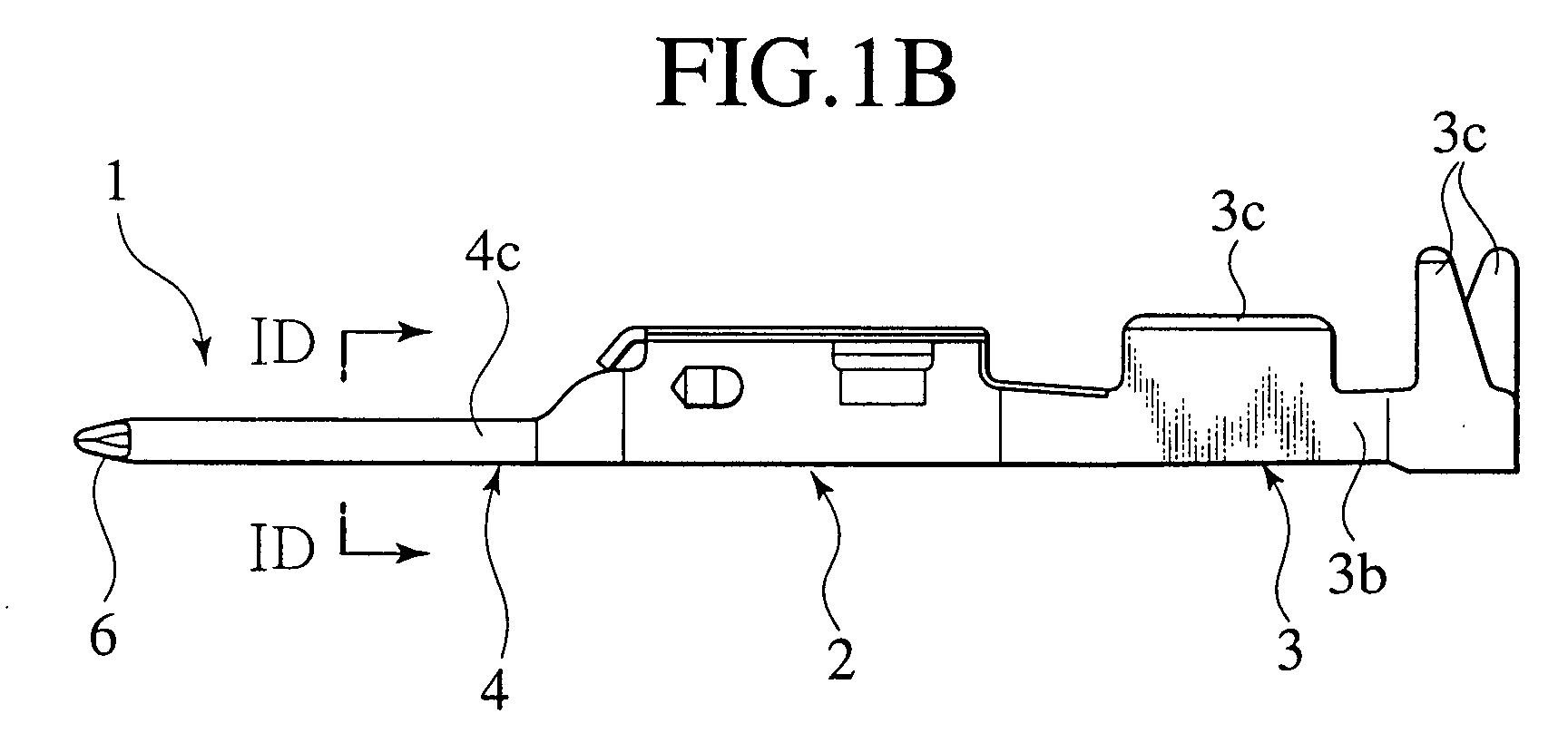
- the connector terminal 1 is composed of a terminal base portion 2, an electric wire fixing portion 3 extending on a back end of the terminal base portion 2, and a tab 4 extending on a tip end of the terminal base portion 2 for contacting with an opponent terminal.
- the electric wire fixing portion 3 includes a bottom face portion 3a, a pair of side plate portions 3b standing on the right and left sides of the bottom face portion 3a, and electric wire caulking portions 3c extending above the respective side plate portions 3b.
- an end of an electric wire (not shown) is inserted into a space defined by the bottom face portion 3a and the pair of side plate portions 3b, and the electric wire is fastened by bending the electric wire caulking portions 3c so as to overlap the inserted electric wire.
- the tab 4 is composed of a bottom face portion 4a, an intermediate plate portion 4b formed by bending a portion extending from one of right and left sides of the bottom face portion 4a, and an upper face portion 4c formed by bending another portion extending from the other one of the right and left sides of the bottom face portion 4a.
- the intermediate plate portion 4b is provided almost all over from a foot portion to a portion slightly shorter than a tip end portion of the tab 4, and is bent in a manner that a lower plane thereof substantially contacts with the bottom face portion 4a.
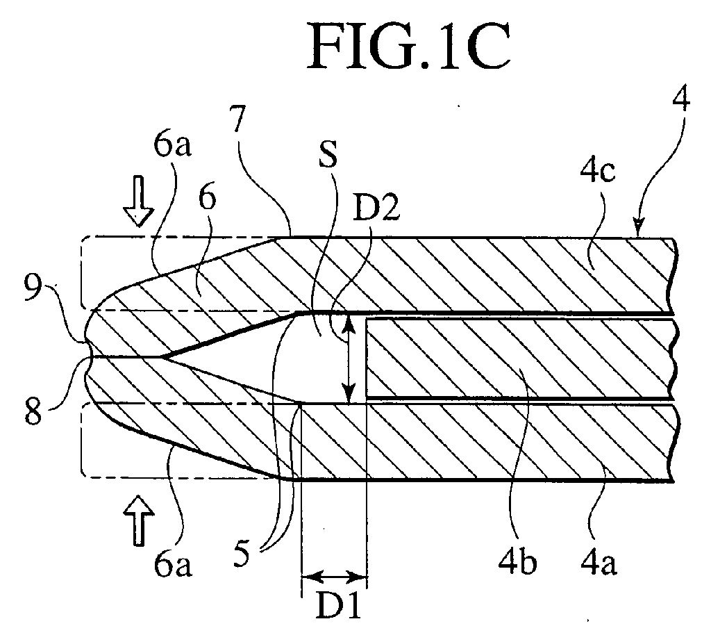
- a tip end position of the intermediate plate portion 4b is set back from internal bending points 5 of the bottom face portion 4a and the upper face portion 4c to be bent upon formation of the after-mentioned tapered portion 6 toward the foot portion of the tab 4 by a distance D1 (see FIG. 1C).
- the upper face portion 4c is provided all over from the foot portion to the tip end portion and bent such that a lower plane thereof substantially contacts with the intermediate plate portion 4b. In other words , the upper face portion 4c and the intermediate plate portion 4b are bent in an overlapping manner. Accordingly, as shown in FIG.
- the bottom face portion 4a, the intermediate plate portion 4b and the upper face portion 4c collectively constitute a threefold overlapping structure in a region all over from the foot portion to the portion slightly shorter than the tip end portion.
- the intermediate plate portion 4b is not interposed at the tip end portion of the tab 4 between the upper face portion 4c and the bottom face portion 4a, tip end portions of the upper face portion 4c and the bottom face portion 4a collectively define an inner space S having a distance D2, which is almost as thick as the intermediate plate portion 4b.
- tip end portions of the bottom face portion 4a and the upper face portion 4c are formed into the tapered portion 6 by bending, which tapers off to a point.
- bending which tapers off to a point.
- the bottom face portion 4a and the upper face portion 4c are bent and formed collectively into a tapered shape as illustrated with solid lines in FIG. 1C.
- the connecter terminal 1 if pressure is applied so as to bend the tip end portions of the bottom face portion 4a and the upper face portion 4c in the directions for allowing the both portions to approach to each other, then smoothly curved corners are formed at bending points 7 (as shown in FIG. 1C) of tapered faces 6a on outer faces of the bottom face portion 4a and the upper face portion 4c. Moreover, excessive mass of the tip end portions of the inner faces of the bottom face portion 4a and the upper face portion 4c abutting on each other may flow out of a front end of the mutually abutting position to generate burrs 8. However, in the position where the burrs 8 may be generated, a concave 9 (as shown in FIG.
- the tab 4 includes the intermediate plate portion 4b intervening between the bottom face portion 4a and the upper face portion 4c, and the tip end position of the intermediate plate portion 4b is set back from the internal bending points 5 of the bottom face portion 4a and the upper face portion 4b to be bent upon formation of the tapered portion 6 toward the foot portion of the tab 4. Accordingly, the intermediate plate portion 4b does not interfere in the process of bending the tip end portions of the bottom face portion 4a and the upper face portion 4c. In this way, it is possible to form the tapered portion 6 reliably.
- a tip end position of an intermediate plate portion 14b is located at internal bending points 15 of a bottom face portion 14a and an upper face portion 14c to be bent upon formation of a tapered portion 16. Since other parts of the constitution of the connector terminal 11 are the same as those in the first embodiment, illustration thereof is omitted.
- the connector terminal 11 has functions and effects similar to those in the first embodiment.
- the tip end position of the intermediate plate portion 14b is located at the internal bending points 15 of the bottom face portion 14a and the upper face portion 14b to be bent upon formation of the tapered portion 16. Since the intermediate plate portion 14b reaches the internal bending points 15, flatness and strength of the tab 14 can be enhanced.
- the foot portion of the tab 4 or 14 is formed as the threefold structure composed of the bottom face portion 4a or 14a, the intermediate plate portion 4b or 14b, and the upper face portion 4c or 14c. Accordingly, geometrical moment of inertia and a section modulus at the foot portion of the tab 4 or 14 are increased, whereby strength and rigidity at the foot portion of the tab 4 or 14 are enhanced.
- the intermediate plate portion 4b or 14b, and the upper face portion 4c or 14c are bent almost in the same condition throughout the tab 4 or 14 from the foot portion to the tip end portion thereof. Accordingly, geometrical moment of inertia and a section modulus at a portion other than the foot portion of the tab 4 or 14 are also increased, whereby strength and rigidity at the portion other than the foot portion of the tab 4 or 14 are also enhanced. As a result, strength and rigidity of the tab 4 or 14 are enhanced as a whole.
- a connector terminal 21 is formed by bending a metal plate of a predetermined shape.
- the connector terminal 21 is composed of a terminal base portion 22, an electric wire fixing portion 23 extending on a back end of the terminal base portion 22, and a tab 24 extending on a tip end of the terminal base portion 22 for contacting with an opponent terminal.
- the electric wire fixing portion 23 includes a bottom face portion 23a, a pair of side plate portions 23b standing on the right and left sides of the bottom face portion 23a, and electric wire caulking portions 23c extending above the respective side plate portions 23b.
- an end of an electric wire (not shown) is inserted into a space defined by the bottom face portion 23a and the pair of side plate portions 23b, and the electric wire is fastened by bending the electric wire caulking portions 23c so as to overlap the inserted electric wire.
- the tab 24 includes a bottom face portion 24a, an upper face portion 24b formed by bending a portion extending from one of right and left sides of the bottom face portion 24a, and a folded portion 24c formed by bending another portion extending from the other one of the right and left sides thereof.
- the upper face portion 24b is provided all over from a foot portion to a tip end portion and bent such that a lower plane thereof overlaps the bottom face portion 24a with provision of an inner space S having a distance D3 against the bottom face portion 24a as shown in FIG. 3E.
- the folded portion 24c is provided only on the foot portion and bent such that a lower plane thereof substantially contacts with the upper face portion 24b as shown in FIG. 3D.
- the folded portion 24c and the upper face portion 24b are disposed with provision of the inner space S against the bottom face portion 24a and bent in an overlapping manner. Accordingly, the foot portion of the tab 24 is formed as threefold consisting of the bottom face portion 24a, the upper face portion 24b and the folded portion 24c, and the portion other than the foot portion of the tab 24 is formed as twofold consisting of the bottom face portion 24a and the upper face portion 24b, respectively.
- the tab 24 can be inserted into an opponent terminal smoothly without being caught by the opponent terminal, as similar to the first embodiment.
- the tab 24 has a simplified constitution with the inner space S defined between the bottom face portion 24a and the upper face portion 24b in almost an entire area from the tip end to the foot portion of the tab 24, contributing to simplification of formation of the tab 24.
- the foot portion of the tab 24 is formed as threefold consisting of the bottom face portion 24a, the upper face portion 24b and the folded portion 24c. Accordingly, geometrical moment of inertia and a section modulus at the foot portion of the tab 24 are increased, whereby strength and rigidity at the foot portion of the tab 24 are further enhanced.
- the upper face portion 24b and the folded portion 24c of the foot portion of the tab 24 are bent so as to overlap each other with provision of the inner space S against the bottom face portion 24a. Therefore, the foot portion of the tab 24 shows geometrical moment of inertia and a section modulus which are higher than those in the case of overlapping the bottom face portion 24a, the upper face portion 24b and the folded portion 24c in a substantially contacting manner (the first and the second embodiments). Hence, strength and rigidity of the foot portion of the tab 24 are further enhanced.
- the upper face portion 24b at a portion other than the foot portion of the tab 24 is bent so as to overlap each other with provision of the inner space S against the bottom face portion 24a. Therefore, the portion other than the foot portion of the tab 24 shows geometrical moment of inertia and a section modulus which are higher than those in the case of overlapping the bottom face portion 24a and the upper face portion 24b in the substantially contacting manner (the first and the second embodiments). Hence, strength and rigidity of the portion other than the foot portion of the tab 24 are also enhanced. As a result, strength and rigidity of the tab 24 are enhanced as a whole.
Landscapes
- Connections Effected By Soldering, Adhesion, Or Permanent Deformation (AREA)
- Coupling Device And Connection With Printed Circuit (AREA)
- Connector Housings Or Holding Contact Members (AREA)
- Processing Of Terminals (AREA)
- Cable Accessories (AREA)
- Manufacturing Of Electrical Connectors (AREA)
- Details Of Connecting Devices For Male And Female Coupling (AREA)
Abstract

Description
Claims (8)
- A connector terminal comprising:wherein the bottom face portion and the upper face portion are bent so that tip ends thereof approach to each other, and define an inner space therebetween.a terminal base portion; anda tab extending from the terminal base portion to be inserted into an opponent terminal, the tab including:a bottom face portion; andan upper face portion extending from the bottom face portion, formed by bending so as to overlap the bottom face portion, the bottom face portion and the upper face portion collectively forming a tapered portion tapering off to a point at a tip end of the tab,
- The connector terminal according to claim 1, wherein the tab includes an intermediate plate portion intervening between the bottom face portion and the upper face portion, and
a tip end of the intermediate plate portion is closer to a foot portion of the tab than internal bending points of the bottom face portion and the upper face portion of the tapered portion. - The connector terminal according to claim 1, wherein the tab includes an intermediate plate portion intervening between the bottom face portion and the upper face portion, and
a tip end of the intermediate plate portion is set in a position identical to internal bending points of the bottom face portion and the upper face portion of the tapered portion. - The connector terminal according to claim 1, wherein the tab is configured with the inner space in a region from a tip end to a foot portion thereof.
- A connector terminal comprising:wherein the bottom face portion and the upper face portion are bent so that tip ends thereof approach to each other, and generate a concave at the tip end of the tab.a terminal base portion; anda tab extending from the terminal base portion to be inserted into an opponent terminal, the tab including:a bottom face portion; andan upper face portion extending from the bottom face portion, formed by bending so as to overlap the bottom face portion, the bottom face portion and the upper face portion collectively forming a tapered portion at a tip end of the tab,
- The connector terminal according to claim 5, wherein the tab includes an intermediate plate portion intervening between the bottom face portion and the upper face portion, and
a tip end of the intermediate plate portion is closer to a foot portion of the tab than internal bending points of the bottom face portion and the upper face portion of the tapered portion. - The connector terminal according to claim 5, wherein the tab includes an intermediate plate portion intervening between the bottom face portion and the upper face portion, and
a tip end of the intermediate plate portion is set in a position identical to internal bending points of the bottom face portion and the upper face portion of the tapered portion. - The connector terminal according to claim 5, wherein the tab is configured with an inner space defined between the bottom face portion and the upper face portion in a region from a tip end to a foot portion of the tab.
Applications Claiming Priority (2)
| Application Number | Priority Date | Filing Date | Title |
|---|---|---|---|
| JP2001220557A JP2003036909A (en) | 2001-07-19 | 2001-07-19 | Connector terminal |
| JP2001220557 | 2001-07-19 |
Publications (3)
| Publication Number | Publication Date |
|---|---|
| EP1278270A2 true EP1278270A2 (en) | 2003-01-22 |
| EP1278270A3 EP1278270A3 (en) | 2004-01-28 |
| EP1278270B1 EP1278270B1 (en) | 2005-03-30 |
Family
ID=19054360
Family Applications (1)
| Application Number | Title | Priority Date | Filing Date |
|---|---|---|---|
| EP02015670A Expired - Lifetime EP1278270B1 (en) | 2001-07-19 | 2002-07-17 | Connector terminal |
Country Status (5)
| Country | Link |
|---|---|
| US (1) | US6638117B2 (en) |
| EP (1) | EP1278270B1 (en) |
| JP (1) | JP2003036909A (en) |
| KR (1) | KR100510275B1 (en) |
| DE (1) | DE60203447T2 (en) |
Families Citing this family (8)
| Publication number | Priority date | Publication date | Assignee | Title |
|---|---|---|---|---|
| JP3823811B2 (en) * | 2001-11-22 | 2006-09-20 | 住友電装株式会社 | Male tab |
| JP3814221B2 (en) * | 2002-04-18 | 2006-08-23 | 住友電装株式会社 | Male terminal fitting |
| ATE426260T1 (en) * | 2005-07-21 | 2009-04-15 | Framatome Connectors Int | ELECTRICAL PLUG CONNECTION |
| US7594832B2 (en) * | 2005-12-28 | 2009-09-29 | Hitachi Cable, Ltd. | Connector structure with a u-shaped cross section having a male terminal and a female terminal |
| US7857669B1 (en) * | 2009-08-05 | 2010-12-28 | Hamilton Sundstrand Corporation | High power electrical interface connection |
| JP5644919B1 (en) * | 2013-08-26 | 2014-12-24 | 第一精工株式会社 | Connector terminal and manufacturing method thereof |
| CN113517584A (en) * | 2020-04-09 | 2021-10-19 | 泰科电子(上海)有限公司 | Connection terminal and connector |
| JP7529958B1 (en) | 2024-01-30 | 2024-08-07 | 幸文 町田 | Male terminal |
Family Cites Families (15)
| Publication number | Priority date | Publication date | Assignee | Title |
|---|---|---|---|---|
| US3969012A (en) * | 1974-10-31 | 1976-07-13 | Bunker Ramo Corporation | Stamped contact tip |
| JPS5749908Y2 (en) * | 1978-10-31 | 1982-11-01 | ||
| DE3804977A1 (en) * | 1988-02-18 | 1989-08-31 | Daut & Rietz Trw | FLAT CONTACT SPRING FOR CONNECTORS OF ELECTRICAL CONNECTORS |
| DE4200109A1 (en) * | 1992-01-04 | 1993-07-08 | Daut & Rietz Trw | KNIFE CONTACT FOR ELECTRICAL CONNECTORS |
| JPH0734563U (en) * | 1993-12-08 | 1995-06-23 | 住友電装株式会社 | Male terminal fitting |
| JP3046731B2 (en) * | 1994-11-30 | 2000-05-29 | 矢崎総業株式会社 | Male terminal and method of manufacturing male terminal |
| JP3177144B2 (en) * | 1996-02-14 | 2001-06-18 | 矢崎総業株式会社 | Male terminal |
| JP3478010B2 (en) * | 1996-07-26 | 2003-12-10 | 住友電装株式会社 | Male terminal fitting |
| DE29808642U1 (en) * | 1998-05-14 | 1999-08-12 | Robert Bosch Gmbh, 70469 Stuttgart | Contact element |
| JPH11329545A (en) * | 1998-05-19 | 1999-11-30 | Yazaki Corp | Male terminal |
| JP3473527B2 (en) * | 1999-12-08 | 2003-12-08 | 住友電装株式会社 | Pressure contact terminal and method of manufacturing the same |
| JP3480708B2 (en) * | 2000-03-15 | 2003-12-22 | 住友電装株式会社 | Male terminal fitting |
| JP4132618B2 (en) * | 2000-09-08 | 2008-08-13 | 矢崎総業株式会社 | Terminal bracket tab |
| JP2003036911A (en) * | 2001-02-13 | 2003-02-07 | Yazaki Corp | Male terminal fitting |
| JP2003036910A (en) * | 2001-07-19 | 2003-02-07 | Yazaki Corp | Connector terminal |
-
2001
- 2001-07-19 JP JP2001220557A patent/JP2003036909A/en active Pending
-
2002
- 2002-07-17 EP EP02015670A patent/EP1278270B1/en not_active Expired - Lifetime
- 2002-07-17 DE DE60203447T patent/DE60203447T2/en not_active Expired - Lifetime
- 2002-07-17 US US10/196,156 patent/US6638117B2/en not_active Expired - Lifetime
- 2002-07-19 KR KR10-2002-0042388A patent/KR100510275B1/en not_active Expired - Fee Related
Also Published As
| Publication number | Publication date |
|---|---|
| EP1278270A3 (en) | 2004-01-28 |
| DE60203447T2 (en) | 2006-02-09 |
| DE60203447D1 (en) | 2005-05-04 |
| US20030017755A1 (en) | 2003-01-23 |
| JP2003036909A (en) | 2003-02-07 |
| KR20030009208A (en) | 2003-01-29 |
| EP1278270B1 (en) | 2005-03-30 |
| KR100510275B1 (en) | 2005-08-26 |
| US6638117B2 (en) | 2003-10-28 |
Similar Documents
| Publication | Publication Date | Title |
|---|---|---|
| JP3823811B2 (en) | Male tab | |
| EP1278269B1 (en) | Connector terminal | |
| US7114253B2 (en) | Male terminal fitting and method of manufacturing the same | |
| JP3533536B2 (en) | Female terminal fitting | |
| US5664974A (en) | Male terminal and method of manufacturing thereof | |
| JP3202561B2 (en) | Male terminal fitting | |
| JPH09223532A (en) | Male terminal | |
| EP1278270B1 (en) | Connector terminal | |
| EP1388912A1 (en) | A male terminal fitting and method of forming it | |
| JP3073411B2 (en) | Contact piece and card connector including the same | |
| JPH0927368A (en) | Female terminal | |
| US6786781B2 (en) | Male contact | |
| JP2001006784A (en) | Terminal structure | |
| JPH10255864A (en) | Crimp terminal | |
| JP2003051351A (en) | Male contact and method of manufacturing the same | |
| JP2005123048A (en) | Connection terminal and joint connector using the connection terminal | |
| JP2022037547A (en) | Terminal fittings and chain terminals | |
| US6325658B2 (en) | Insulation-displacement terminal fitting and production method therefor | |
| JP3082613B2 (en) | Female terminal fitting | |
| JP2598586Y2 (en) | Connector connection structure | |
| JPH031897Y2 (en) | ||
| JPH0612626Y2 (en) | contact | |
| JPS5915406Y2 (en) | Connecting terminal | |
| EP3700019A1 (en) | Female terminal for electrical connections | |
| JP2003208940A (en) | contact |
Legal Events
| Date | Code | Title | Description |
|---|---|---|---|
| PUAI | Public reference made under article 153(3) epc to a published international application that has entered the european phase |
Free format text: ORIGINAL CODE: 0009012 |
|
| 17P | Request for examination filed |
Effective date: 20020717 |
|
| AK | Designated contracting states |
Kind code of ref document: A2 Designated state(s): AT BE BG CH CY CZ DE DK EE ES FI FR GB GR IE IT LI LU MC NL PT SE SK TR |
|
| AX | Request for extension of the european patent |
Free format text: AL;LT;LV;MK;RO;SI |
|
| PUAL | Search report despatched |
Free format text: ORIGINAL CODE: 0009013 |
|
| AK | Designated contracting states |
Kind code of ref document: A3 Designated state(s): AT BE BG CH CY CZ DE DK EE ES FI FR GB GR IE IT LI LU MC NL PT SE SK TR |
|
| AX | Request for extension of the european patent |
Extension state: AL LT LV MK RO SI |
|
| 17Q | First examination report despatched |
Effective date: 20040426 |
|
| GRAP | Despatch of communication of intention to grant a patent |
Free format text: ORIGINAL CODE: EPIDOSNIGR1 |
|
| GRAP | Despatch of communication of intention to grant a patent |
Free format text: ORIGINAL CODE: EPIDOSNIGR1 |
|
| AKX | Designation fees paid |
Designated state(s): DE FR GB |
|
| GRAS | Grant fee paid |
Free format text: ORIGINAL CODE: EPIDOSNIGR3 |
|
| GRAA | (expected) grant |
Free format text: ORIGINAL CODE: 0009210 |
|
| AK | Designated contracting states |
Kind code of ref document: B1 Designated state(s): DE FR GB |
|
| REG | Reference to a national code |
Ref country code: GB Ref legal event code: FG4D |
|
| REF | Corresponds to: |
Ref document number: 60203447 Country of ref document: DE Date of ref document: 20050504 Kind code of ref document: P |
|
| REG | Reference to a national code |
Ref country code: IE Ref legal event code: FG4D |
|
| ET | Fr: translation filed | ||
| PLBE | No opposition filed within time limit |
Free format text: ORIGINAL CODE: 0009261 |
|
| STAA | Information on the status of an ep patent application or granted ep patent |
Free format text: STATUS: NO OPPOSITION FILED WITHIN TIME LIMIT |
|
| 26N | No opposition filed |
Effective date: 20060102 |
|
| REG | Reference to a national code |
Ref country code: FR Ref legal event code: PLFP Year of fee payment: 15 |
|
| REG | Reference to a national code |
Ref country code: FR Ref legal event code: PLFP Year of fee payment: 16 |
|
| REG | Reference to a national code |
Ref country code: FR Ref legal event code: PLFP Year of fee payment: 17 |
|
| PGFP | Annual fee paid to national office [announced via postgrant information from national office to epo] |
Ref country code: FR Payment date: 20200611 Year of fee payment: 19 |
|
| PGFP | Annual fee paid to national office [announced via postgrant information from national office to epo] |
Ref country code: DE Payment date: 20200707 Year of fee payment: 19 Ref country code: GB Payment date: 20200708 Year of fee payment: 19 |
|
| REG | Reference to a national code |
Ref country code: DE Ref legal event code: R119 Ref document number: 60203447 Country of ref document: DE |
|
| GBPC | Gb: european patent ceased through non-payment of renewal fee |
Effective date: 20210717 |
|
| PG25 | Lapsed in a contracting state [announced via postgrant information from national office to epo] |
Ref country code: GB Free format text: LAPSE BECAUSE OF NON-PAYMENT OF DUE FEES Effective date: 20210717 Ref country code: DE Free format text: LAPSE BECAUSE OF NON-PAYMENT OF DUE FEES Effective date: 20220201 |
|
| PG25 | Lapsed in a contracting state [announced via postgrant information from national office to epo] |
Ref country code: FR Free format text: LAPSE BECAUSE OF NON-PAYMENT OF DUE FEES Effective date: 20210731 |