EP1278228A1 - Cathode ray tube - Google Patents
Cathode ray tube Download PDFInfo
- Publication number
- EP1278228A1 EP1278228A1 EP01999954A EP01999954A EP1278228A1 EP 1278228 A1 EP1278228 A1 EP 1278228A1 EP 01999954 A EP01999954 A EP 01999954A EP 01999954 A EP01999954 A EP 01999954A EP 1278228 A1 EP1278228 A1 EP 1278228A1
- Authority
- EP
- European Patent Office
- Prior art keywords
- panel
- ray tube
- cathode ray
- band
- resin panel
- Prior art date
- Legal status (The legal status is an assumption and is not a legal conclusion. Google has not performed a legal analysis and makes no representation as to the accuracy of the status listed.)
- Withdrawn
Links
Images


Classifications
-
- H—ELECTRICITY
- H01—ELECTRIC ELEMENTS
- H01J—ELECTRIC DISCHARGE TUBES OR DISCHARGE LAMPS
- H01J29/00—Details of cathode-ray tubes or of electron-beam tubes of the types covered by group H01J31/00
- H01J29/86—Vessels; Containers; Vacuum locks
- H01J29/87—Arrangements for preventing or limiting effects of implosion of vessels or containers
-
- H—ELECTRICITY
- H04—ELECTRIC COMMUNICATION TECHNIQUE
- H04N—PICTORIAL COMMUNICATION, e.g. TELEVISION
- H04N5/00—Details of television systems
- H04N5/64—Constructional details of receivers, e.g. cabinets or dust covers
- H04N5/65—Holding-devices for protective discs or for picture masks
Definitions
- the present invention relates to a cathode ray tube of which vacuum resistance and explosion-proof characteristics can be enhanced, and particularly to one in which a lightweight resin panel is fitted to the surface of a cathode ray tube panel.
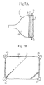
- Figs. 7A and 7B are schematic views for illustrating a conventional cathode ray tube, in which Fig. 7A is a side view, and Fig. 7B is a front view.
- a glass vessel of the cathode ray tube 1' has a structure in which a panel 11 and a funnel 12 are joined by a frit glass 13, and an aperture grille which is a color selection mechanism, an electron gun and the like are sealed in the inside.
- the glass bulb constituting the cathode ray tube must satisfy required performances as to vacuum resistance and explosion-proof characteristics so as to fulfill the characteristics as a vacuum vessel.
- a method of controlling the material thickness of the glass is used. Namely, in order to secure the strength of the glass bulb, it is necessary to enlarge the material thickness of the glass. As for the explosion-proof characteristics, also, a larger glass material thickness is more advantageous.
- the color cathode ray tube has had the tendency toward a larger screen, and the material thickness of the glass of the cathode ray tube tends to increase as the size of the screen increases.
- the weight of the glass has also been increasing.
- the weight of the glass including the panel and the funnel is as large as more than 50 kg.
- a further increase in the size of the cathode ray tube causes a further increase in the weight of the glass, and is difficult to actually carry out.
- a reinforcing method for enhancing the explosion-proof characteristics for example, there is a method of adhering a resin sheet to a panel face plate and an outer peripheral portion of side surfaces and shrink fitting an HS band thereon, as disclosed in Japanese Patent Laid-open No. Hei 8-77950. According to this method, however, the joint strength between the HS band and the panel and the resin sheet is low, and the resin sheet is also sucked in upon implosion, so that it is difficult to prevent the scattering of glass when the implosion energy is increased.
- a cathode ray tube according to the present invention comprises an explosion-proof band surrounding the peripheral edge of a cathode ray tube panel, and a resin panel disposed in the state of covering the surface of the cathode ray tube panel and connected to the explosion-proof band.
- the surface of the cathode ray tube panel and the resin panel may be fixed by an adhesive
- the resin panel and the explosion-proof band may be fixed by an adhesive
- the resin panel and the explosion-proof band may be mechanically fixed by use of bolt/nut pairs, a wire or the like
- the resin panel and the explosion-proof band may be connected through fitting members for fitting to a display device casing which are provided on the explosion-proof band.
- the surface of the cathode ray tube panel is covered with the resin panel, and the resin panel is connected to the explosion-proof band. Therefore, it is possible to supplement the explosion-proof characteristics of the cathode ray tube panel by the lightweight resin panel. In addition, it is possible to prevent the resin panel from being sucked into the inside of the cathode ray tube panel upon implosion, and to hinder the scattering of the panel glass toward the front side by the resin panel.
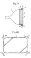
- FIGs. 1A and 1B are schematic views for illustrating First Embodiment, in which Fig. 1A is a side view, and Fig. 1B is a front view of a resin panel.
- a cathode ray tube 1 according to this embodiment has a structure in which a panel 11 and a funnel 12 are joined by a frit glass 13, and an aperture grille which is a color selection mechanism, an electron gun and the like are sealed in the inside thereof.
- An HS band (heat shrink band) 2 as an explosion-proof band for fastening a panel skirt portion in order to enhance explosion-proof characteristics is fitted to an outer peripheral portion of the panel 11 of a glass bulb.
- Fitting portions (generally called "ears") 21 for holding the cathode ray tube on a bezel of a display device casing are fitted to the HS band 2 by welding or the like.
- a resin panel 3 is fitted to the surface (front surface) of the panel 11, and the resin panel 3 is fixed to the HS band 2.
- the glass constituting the vacuum vessel is sucked into the inside of the bulb, is reflected in the inside, and scattered to the exterior through a screen opening portion of the bezel.
- the resin panel 3 is simply adhered to the surface of the panel 11 by an adhesive or the like, upon implosion, the front surface portion of the panel 11 adhered to the resin panel 3 is integrally sucked into the inside of the bulb, and it is impossible to prevent the scattering of the glass from the front surface of the panel 11.
- the resin panel 3 in order to prevent the scattering of the glass from the front surface of the panel 11, the resin panel 3 is fixed to the HS band 2, whereby the resin panel 3 can be prevented from being sucked into the inside of the bulb upon implosion, and an effect as a shield plate against the scattering of glass can be obtained.
- panel side end portions of the HS band 2 are set on roughly the same surface as the surface of the panel 11, whereby the flat surface form resin panel 3 can be fixed to both the surface of the panel 11 and end portions of the HS band 2.
- the material of the resin panel 3 is selected in consideration of optical properties such as refractive index, mechanical properties such as strength and coefficient of expansion, and environmental resistance properties such as degradation.
- examples of the material include polyethylene terephthalate (PET), polycarbonate (PC), acrylic resin and the like.
- PET polyethylene terephthalate
- PC polycarbonate
- acrylic resin acrylic resin
- the adhesive a UV-curable type resin and the like may be mentioned.
- the shape of the resin panel 3 is analogous to the outer circumferential shape of the panel 11 as shown in Fig. 1B, and the resin panel 3 is slightly larger than the HS band 2 in size. With the resin panel 3 thus fixed to the HS band 2 and with the HS band 2 fitted to the bezel through the fitting members 21, the resin panel 3 is equivalently fixed to the bezel, whereby the resin panel 3 can be prevented from being sucked into the inside upon implosion of the cathode ray tube 1, and scattering of glass pieces through the opening portion of the set can be prevented.
- FIGs. 2A and 2B are schematic views for illustrating Second Embodiment, in which Fig. 2A is a side view, and Fig. 2B is a front view of a resin panel.
- the resin panel 3 to be fitted to the surface of a panel 11 and an HS band 2 are fixed through mechanical fixing to fitting members 21 welded to the HS band 2 by pairs of bolt B and nut N.
- projected portions 31 and holes 31a are provided at outer peripheral portions (positions corresponding to the fitting members 21 of the HS band 2) of the resin panel 3, the holes 31a of the projected portions 31 are aligned with holes in the fitting members 21 of the HS band 2, and the bolts B are respectively passed through the aligned holes. Then, the nuts N are fastened to the bolts B, whereby the resin panel 3 is fixed. Actually, the bezel and the HS band 2 are fixed by the bolts B.
- panel side end portions of the HS band 2 are set on roughly the same surface as the front surface of the panel 11, whereby the flat surface form resin panel 3 can be fixed to both the surface of the panel 11 and end portions of the HS band 2.
- the surface of the panel 11 and the resin panel 3 may be fixed by adhesion with an adhesive or the like.
- the resin panel 3 With the resin panel 3 provided with the projected portions 31 and the holes 31a, the resin panel 3 can be fixed to the HS band 2 easily and assuredly, and scattering of glass pieces upon implosion of the cathode ray tube 1 can be prevented.
- the bolts B and the nuts N for fixing the cathode ray tube 1 and the bezel can be utilized, so that the resin panel 3 can be fixed by use of a reduced number of component parts.
- Figs. 3A and 3B are schematic views for illustrating Third Embodiment, in which Fig. 3A is a side view, and Fig. 3B is a front view of a resin panel.
- the resin panel 3 to be fitted to the surface of a panel 11 and an HS band 2 are fixed by use of a wire W.
- a plurality of projected portions 3 provided with holes 31a are provided at outer peripheral portions of the resin panel 3, the resin panel 3 is adhered to the panel 11 of the cathode ray tube 1 and the HS band 2 with a UV-curing resin, and the wire W is passed through the holes 31a of the projected portions 31 of the resin panel 3 and is fixed to the fitting portions 21 of the HS band 2 or to a main body of the HS band 2.
- the resin panel 3 and the HS band 2 can be fixed at a multiplicity of points, the resin panel 3 can be prevented from being sucked into the inside upon implosion, and scattering of glass pieces can be prevented.
- FIGs. 4A and 4B are schematic views for illustrating Fourth Embodiment, in which Fig. 4A is a side view, and Fig. 4B is a front view of a resin panel.
- the resin panel 3 to be fitted to the surface of a panel 11 and an HS band 2 are fixed by use of pairs of bolt B and nut N and a wire W.
- a plurality of projected portions 31 provided with holes 31a are provided at outer peripheral portions of the resin panel 3, and fixing by the bolt B and the nut N is conducted at each of the holes 31a of the projected portions 31 corresponding to fitting members 21 of the HS band 2, whereas fixing by the wire W is conducted at the holes 31a of the other projected portions 31.
- the resin panel 3 and the HS band 2 can be fitted very rigidly, and barrier property against the scattering of glass upon implosion can be enhanced.
- Figs. 5A and 5B are schematic views for illustrating Fifth Embodiment, in which Fig. 5A is a side view, and Fig. 5B is a front view of a resin panel.
- the resin panel 3 is three-dimensionally molded in conformity with the shape of a panel 11 of the cathode ray tube 1, is fitted to the panel 11 from the front side of the panel 11 so as to cover the panel 11, and is adhered with a UV-curing resin.
- the resin panel 3 is formed in a dish shape opened on one side, and is fitted from the front surface side of the panel 11 of the cathode ray tube 1, and the resin panel 3 and an HS band 2 and the panel 11 are fixed with a UV-curing adhesive or the like.
- the resin panel 3 can be easily fitted to the panel 11, and the projected portions for fitting can be unnecessitated, so that natural appearance can be realized. With the resin panel 3 and the HS band 2 connected, the resin panel 3 can be prevented from being sucked into the inside upon implosion, and scattering of glass pieces can be prevented.
- Figs. 6A and 6B are schematic views for illustrating Sixth Embodiment, in which Fig. 6A is a side view, and Fig. 6B is a front view of a resin panel.
- the resin panel 3 is three-dimensionally molded in conformity with the shape of a panel 11 of the cathode ray tube 1, and is fitted to the panel 11 so as to cover the panel 11 from the front side thereof, and fitting members 21 of the panel 11 and the resin panel 3 are fixed by pairs of bolt B and nut N.
- the resin panel 3 is formed in a dish shape opened on one side, and is fitted to the panel 11 of the cathode ray tube 1 so as to cover the panel 11 from the front side thereof, and the resin panel 3 and an HS band 2 and the panel 11 are fixed with a UV-curing adhesive or the like.
- projected portions 31 provided with holes 31a are provided at outer peripheral portions (positions corresponding to the fitting members 21 of the HS band 2) of the resin panel 3, the holes 31a of the projected portions 31 are aligned with holes in the fitting members 21 of the HS band 2, and bolts B are passed through the aligned holes. Then, nuts N are fastened to the bolts B, whereby the resin plate 3 is fixed.
- a bezel and the HS band 2 are fixed by the bolts B.
- the resin panel 3 can be easily fitted to the panel 11 of the cathode ray tube 1, can be rigidly fixed by the adhesive and the combination of the bolts B and the nuts N, and can be prevented from being sucked into the inside upon implosion, so that scattering of glass pieces can be prevented.
- the present invention by not only adhering the resin panel to the panel but also mechanically fixing the resin panel with the HS band, it is possible to enhance explosion-proof characteristics. Particularly, even where the material thickness of glass is reduced in a lightweight glass bulb and implosion energy is increased, explosion-proof characteristics can be enhanced with minimized increases in weight and cost, and a reduction in weight of the cathode ray tube can be realized.
Landscapes
- Vessels, Lead-In Wires, Accessory Apparatuses For Cathode-Ray Tubes (AREA)
Abstract
A cathode ray tube in which a reduction in weight
can be contrived and scattering of glass upon implosion
can be prevented effectively. The cathode ray tube
comprises an HS band (2) surrounding the peripheral edge
of a panel (11), and a resin panel (3) disposed in the
state of covering the surface of the panel (11) and
connected to the HS band (2). The surface of the panel
(11) and the resin panel (3) may be fixed with an
adhesive, the resin panel (3) and the HS band- (2) may be
fixed with an adhesive, the resin panel (3) and the HS
band (2) may be mechanically fixed by use of bolt/nut
pairs, a wire or the like, and the resin panel (3) and
the HS band (2) may be connected through fitting members
(21) for fitting to a display device casing which are
provided on the HS band (2).
Description
- The present invention relates to a cathode ray tube of which vacuum resistance and explosion-proof characteristics can be enhanced, and particularly to one in which a lightweight resin panel is fitted to the surface of a cathode ray tube panel.
- Figs. 7A and 7B are schematic views for illustrating a conventional cathode ray tube, in which Fig. 7A is a side view, and Fig. 7B is a front view. Namely, a glass vessel of the cathode ray tube 1' has a structure in which a
panel 11 and afunnel 12 are joined by afrit glass 13, and an aperture grille which is a color selection mechanism, an electron gun and the like are sealed in the inside. - An HS band (heat shrink band) 2 for fastening a panel skirt portion in order to enhance explosion-proof characteristics and fitting members (generally called "ears") 21 for holding the cathode ray tube, welded to the
HS band 2, are fitted to an outer peripheral portion of thepanel 11 of the glass bulb. - Since the inside of the vessel is maintained in a vacuum condition, a pressure of 1 atm is always exerted on the glass bulb. Therefore, the glass bulb constituting the cathode ray tube must satisfy required performances as to vacuum resistance and explosion-proof characteristics so as to fulfill the characteristics as a vacuum vessel.
- In general, in order to realize these performances in the vacuum vessel using a glass, a method of controlling the material thickness of the glass is used. Namely, in order to secure the strength of the glass bulb, it is necessary to enlarge the material thickness of the glass. As for the explosion-proof characteristics, also, a larger glass material thickness is more advantageous.
- In recent years, the color cathode ray tube has had the tendency toward a larger screen, and the material thickness of the glass of the cathode ray tube tends to increase as the size of the screen increases. Attendant on this, the weight of the glass has also been increasing. For example, in the case of a 36-inch class of cathode ray tube, the weight of the glass including the panel and the funnel is as large as more than 50 kg. A further increase in the size of the cathode ray tube causes a further increase in the weight of the glass, and is difficult to actually carry out.
- In order to solve the problem of the increase in weight due to the increase in screen size of the color cathode ray tube from the viewpoint of energy saving and cost saving, a reduction in weight of the glass has been investigated. This is to achieve a reduction in weight of the glass by a method of enhancing the mechanical strength of the glass by a tempering technique and thereby reducing the material thickness of the glass. By this method, it is possible to reduce the material thickness of the glass while securing vacuum-resisting strength.
- As for the explosion-proof characteristics upon the reduction in weight of the glass, however, an increase in the stress on the glass and the reduction in weight of the glass result in that implosion energy increases and it becomes difficult to obtain sufficient explosion-proof characteristics.
- As a reinforcing method for enhancing the explosion-proof characteristics, for example, there is a method of adhering a resin sheet to a panel face plate and an outer peripheral portion of side surfaces and shrink fitting an HS band thereon, as disclosed in Japanese Patent Laid-open No. Hei 8-77950. According to this method, however, the joint strength between the HS band and the panel and the resin sheet is low, and the resin sheet is also sucked in upon implosion, so that it is difficult to prevent the scattering of glass when the implosion energy is increased.
- The present invention has been made in order to solve the above-mentioned problems. Namely, a cathode ray tube according to the present invention comprises an explosion-proof band surrounding the peripheral edge of a cathode ray tube panel, and a resin panel disposed in the state of covering the surface of the cathode ray tube panel and connected to the explosion-proof band.
- The surface of the cathode ray tube panel and the resin panel may be fixed by an adhesive, the resin panel and the explosion-proof band may be fixed by an adhesive, the resin panel and the explosion-proof band may be mechanically fixed by use of bolt/nut pairs, a wire or the like, and the resin panel and the explosion-proof band may be connected through fitting members for fitting to a display device casing which are provided on the explosion-proof band.
- According to the present invention as above, the surface of the cathode ray tube panel is covered with the resin panel, and the resin panel is connected to the explosion-proof band. Therefore, it is possible to supplement the explosion-proof characteristics of the cathode ray tube panel by the lightweight resin panel. In addition, it is possible to prevent the resin panel from being sucked into the inside of the cathode ray tube panel upon implosion, and to hinder the scattering of the panel glass toward the front side by the resin panel.
-
- Figs. 1A and 1B are schematic views for illustrating First Embodiment;
- Figs. 2A and 2B are schematic views for illustrating Second Embodiment;
- Figs. 3A and 3B are schematic views for illustrating Third Embodiment;
- Figs. 4A and 4B are schematic views for illustrating Fourth Embodiment;
- Figs. 5A and 5B are schematic views for illustrating Fifth Embodiment;
- Figs. 6A and 6B are schematic views for illustrating Sixth Embodiment; and
- Figs. 7A and 7B are schematic views for illustrating a conventional cathode ray tube.
-
- Now, embodiments of the present invention will be described below. Figs. 1A and 1B are schematic views for illustrating First Embodiment, in which Fig. 1A is a side view, and Fig. 1B is a front view of a resin panel. A
cathode ray tube 1 according to this embodiment has a structure in which apanel 11 and afunnel 12 are joined by afrit glass 13, and an aperture grille which is a color selection mechanism, an electron gun and the like are sealed in the inside thereof. - An HS band (heat shrink band) 2 as an explosion-proof band for fastening a panel skirt portion in order to enhance explosion-proof characteristics is fitted to an outer peripheral portion of the
panel 11 of a glass bulb. Fitting portions (generally called "ears") 21 for holding the cathode ray tube on a bezel of a display device casing are fitted to theHS band 2 by welding or the like. - In such a
cathode ray tube 1, in this embodiment, for the purpose of preventing the scattering of glass from the front surface of thepanel 11 in order to enhance explosion-proof characteristics, aresin panel 3 is fitted to the surface (front surface) of thepanel 11, and theresin panel 3 is fixed to theHS band 2. - At the time of implosion of the
cathode ray tube 1, the glass constituting the vacuum vessel is sucked into the inside of the bulb, is reflected in the inside, and scattered to the exterior through a screen opening portion of the bezel. Here, where theresin panel 3 is simply adhered to the surface of thepanel 11 by an adhesive or the like, upon implosion, the front surface portion of thepanel 11 adhered to theresin panel 3 is integrally sucked into the inside of the bulb, and it is impossible to prevent the scattering of the glass from the front surface of thepanel 11. - In this embodiment, in order to prevent the scattering of the glass from the front surface of the
panel 11, theresin panel 3 is fixed to theHS band 2, whereby theresin panel 3 can be prevented from being sucked into the inside of the bulb upon implosion, and an effect as a shield plate against the scattering of glass can be obtained. - In First Embodiment, for fixing the
resin panel 3 to theHS band 2 by the adhesive, panel side end portions of theHS band 2 are set on roughly the same surface as the surface of thepanel 11, whereby the flat surfaceform resin panel 3 can be fixed to both the surface of thepanel 11 and end portions of theHS band 2. - In addition, with the surface (front surface) of the
panel 11 and theresin panel 3 fixed by adhesion with an adhesive or the like, a role of shock absorption relative to the surface of thepanel 11 is played. - The material of the
resin panel 3 is selected in consideration of optical properties such as refractive index, mechanical properties such as strength and coefficient of expansion, and environmental resistance properties such as degradation. In concrete, examples of the material include polyethylene terephthalate (PET), polycarbonate (PC), acrylic resin and the like. As the adhesive, a UV-curable type resin and the like may be mentioned. - The shape of the
resin panel 3 is analogous to the outer circumferential shape of thepanel 11 as shown in Fig. 1B, and theresin panel 3 is slightly larger than theHS band 2 in size. With theresin panel 3 thus fixed to theHS band 2 and with theHS band 2 fitted to the bezel through thefitting members 21, theresin panel 3 is equivalently fixed to the bezel, whereby theresin panel 3 can be prevented from being sucked into the inside upon implosion of thecathode ray tube 1, and scattering of glass pieces through the opening portion of the set can be prevented. - Particularly, even where the material thickness of glass is reduced by use of a lightweight glass bulb and implosion energy is increased, explosion-proof characteristics can be enhanced with a minimized increase in weight.
- Next, Second Embodiment will be described. Figs. 2A and 2B are schematic views for illustrating Second Embodiment, in which Fig. 2A is a side view, and Fig. 2B is a front view of a resin panel. In a
cathode ray tube 1 according- to Second Embodiment, theresin panel 3 to be fitted to the surface of apanel 11 and anHS band 2 are fixed through mechanical fixing tofitting members 21 welded to theHS band 2 by pairs of bolt B and nut N. - For such fixing, as shown in Fig. 2B, projected
portions 31 andholes 31a are provided at outer peripheral portions (positions corresponding to thefitting members 21 of the HS band 2) of theresin panel 3, theholes 31a of the projectedportions 31 are aligned with holes in thefitting members 21 of theHS band 2, and the bolts B are respectively passed through the aligned holes. Then, the nuts N are fastened to the bolts B, whereby theresin panel 3 is fixed. Actually, the bezel and theHS band 2 are fixed by the bolts B. - In Second Embodiment, in the same manner as in First Embodiment, panel side end portions of the
HS band 2 are set on roughly the same surface as the front surface of thepanel 11, whereby the flat surfaceform resin panel 3 can be fixed to both the surface of thepanel 11 and end portions of theHS band 2. In addition to the fixing of theresin panel 3 and thefitting members 21 of theHS band 2 by the combination of the bolts B and the nuts N, the surface of thepanel 11 and theresin panel 3 may be fixed by adhesion with an adhesive or the like. - In such fixing, with the
resin panel 3 provided with the projectedportions 31 and theholes 31a, theresin panel 3 can be fixed to theHS band 2 easily and assuredly, and scattering of glass pieces upon implosion of thecathode ray tube 1 can be prevented. In addition, the bolts B and the nuts N for fixing thecathode ray tube 1 and the bezel can be utilized, so that theresin panel 3 can be fixed by use of a reduced number of component parts. - Next, Third Embodiment will be described. Figs. 3A and 3B are schematic views for illustrating Third Embodiment, in which Fig. 3A is a side view, and Fig. 3B is a front view of a resin panel. In a
cathode ray tube 1 according to Third Embodiment, theresin panel 3 to be fitted to the surface of apanel 11 and anHS band 2 are fixed by use of a wire W. - Namely, as shown in Fig. 3B, a plurality of projected
portions 3 provided withholes 31a are provided at outer peripheral portions of theresin panel 3, theresin panel 3 is adhered to thepanel 11 of thecathode ray tube 1 and theHS band 2 with a UV-curing resin, and the wire W is passed through theholes 31a of the projectedportions 31 of theresin panel 3 and is fixed to thefitting portions 21 of theHS band 2 or to a main body of theHS band 2. - By this, the
resin panel 3 and theHS band 2 can be fixed at a multiplicity of points, theresin panel 3 can be prevented from being sucked into the inside upon implosion, and scattering of glass pieces can be prevented. - Next, Fourth Embodiment will be described. Figs. 4A and 4B are schematic views for illustrating Fourth Embodiment, in which Fig. 4A is a side view, and Fig. 4B is a front view of a resin panel. In a
cathode ray tube 1 according to Fourth Embodiment, theresin panel 3 to be fitted to the surface of apanel 11 and anHS band 2 are fixed by use of pairs of bolt B and nut N and a wire W. - Namely, as shown in Fig. 4B, a plurality of projected
portions 31 provided withholes 31a are provided at outer peripheral portions of theresin panel 3, and fixing by the bolt B and the nut N is conducted at each of theholes 31a of the projectedportions 31 corresponding to fittingmembers 21 of theHS band 2, whereas fixing by the wire W is conducted at theholes 31a of the other projectedportions 31. - By such fixing, the
resin panel 3 and theHS band 2 can be fitted very rigidly, and barrier property against the scattering of glass upon implosion can be enhanced. - Next, Fifth Embodiment will be described. Figs. 5A and 5B are schematic views for illustrating Fifth Embodiment, in which Fig. 5A is a side view, and Fig. 5B is a front view of a resin panel. In a
cathode ray tube 1 according to Fifth Embodiment, theresin panel 3 is three-dimensionally molded in conformity with the shape of apanel 11 of thecathode ray tube 1, is fitted to thepanel 11 from the front side of thepanel 11 so as to cover thepanel 11, and is adhered with a UV-curing resin. - Namely, as shown in Fig. 5B, the
resin panel 3 is formed in a dish shape opened on one side, and is fitted from the front surface side of thepanel 11 of thecathode ray tube 1, and theresin panel 3 and anHS band 2 and thepanel 11 are fixed with a UV-curing adhesive or the like. - By use of such a
resin panel 3, theresin panel 3 can be easily fitted to thepanel 11, and the projected portions for fitting can be unnecessitated, so that natural appearance can be realized. With theresin panel 3 and theHS band 2 connected, theresin panel 3 can be prevented from being sucked into the inside upon implosion, and scattering of glass pieces can be prevented. - Next, Sixth Embodiment will be described. Figs. 6A and 6B are schematic views for illustrating Sixth Embodiment, in which Fig. 6A is a side view, and Fig. 6B is a front view of a resin panel. In a
cathode ray tube 1 according to Sixth Embodiment, theresin panel 3 is three-dimensionally molded in conformity with the shape of apanel 11 of thecathode ray tube 1, and is fitted to thepanel 11 so as to cover thepanel 11 from the front side thereof, andfitting members 21 of thepanel 11 and theresin panel 3 are fixed by pairs of bolt B and nut N. - For such fixing, as shown in Fig. 6B, the
resin panel 3 is formed in a dish shape opened on one side, and is fitted to thepanel 11 of thecathode ray tube 1 so as to cover thepanel 11 from the front side thereof, and theresin panel 3 and anHS band 2 and thepanel 11 are fixed with a UV-curing adhesive or the like. - Further, projected
portions 31 provided withholes 31a are provided at outer peripheral portions (positions corresponding to thefitting members 21 of the HS band 2) of theresin panel 3, theholes 31a of the projectedportions 31 are aligned with holes in thefitting members 21 of theHS band 2, and bolts B are passed through the aligned holes. Then, nuts N are fastened to the bolts B, whereby theresin plate 3 is fixed. In practice, a bezel and theHS band 2 are fixed by the bolts B. - By such fixing, the
resin panel 3 can be easily fitted to thepanel 11 of thecathode ray tube 1, can be rigidly fixed by the adhesive and the combination of the bolts B and the nuts N, and can be prevented from being sucked into the inside upon implosion, so that scattering of glass pieces can be prevented. - As has been described above, according to the present invention, by not only adhering the resin panel to the panel but also mechanically fixing the resin panel with the HS band, it is possible to enhance explosion-proof characteristics. Particularly, even where the material thickness of glass is reduced in a lightweight glass bulb and implosion energy is increased, explosion-proof characteristics can be enhanced with minimized increases in weight and cost, and a reduction in weight of the cathode ray tube can be realized.
Claims (7)
- A cathode ray tube comprising an explosion-proof band surrounding the peripheral edge of a cathode ray tube panel, and a resin panel disposed in the state of covering the surface of said cathode ray tube panel and connected to said explosion-proof band.
- A cathode ray tube as set forth in claim 1, wherein the surface of said cathode ray tube panel and said resin panel are fixed with an adhesive.
- A cathode ray tube as set forth in claim 1, wherein said resin panel and said explosion-proof band are fixed with an adhesive.
- A cathode ray tube as set forth in claim 1, wherein said resin panel and said explosion-proof band are fixed mechanically.
- A cathode ray tube as set forth in claim 4, wherein said resin panel and said explosion-proof band are fixed with bolt/nut pairs.
- A cathode ray tube as set forth in claim 4, wherein said resin panel and said explosion-proof band are fixed with a wire.
- A cathode ray tube as set forth in claim 1, wherein said resin panel and said explosion-proof band are connected through fitting members for fitting to a display device casing.
Applications Claiming Priority (3)
| Application Number | Priority Date | Filing Date | Title |
|---|---|---|---|
| JP2000369380 | 2000-12-05 | ||
| JP2000369380A JP2002170508A (en) | 2000-12-05 | 2000-12-05 | Cathode ray tube |
| PCT/JP2001/010631 WO2002047108A1 (en) | 2000-12-05 | 2001-12-05 | Cathode ray tube |
Publications (1)
| Publication Number | Publication Date |
|---|---|
| EP1278228A1 true EP1278228A1 (en) | 2003-01-22 |
Family
ID=18839428
Family Applications (1)
| Application Number | Title | Priority Date | Filing Date |
|---|---|---|---|
| EP01999954A Withdrawn EP1278228A1 (en) | 2000-12-05 | 2001-12-05 | Cathode ray tube |
Country Status (6)
| Country | Link |
|---|---|
| EP (1) | EP1278228A1 (en) |
| JP (1) | JP2002170508A (en) |
| KR (1) | KR20020070388A (en) |
| CN (1) | CN1397088A (en) |
| TW (1) | TW543065B (en) |
| WO (1) | WO2002047108A1 (en) |
Families Citing this family (1)
| Publication number | Priority date | Publication date | Assignee | Title |
|---|---|---|---|---|
| US7463734B2 (en) * | 2006-02-03 | 2008-12-09 | Sony Ericsson Mobile Communications Ab | Display window cover assemblies and electronic devices and methods using the same |
Family Cites Families (5)
| Publication number | Priority date | Publication date | Assignee | Title |
|---|---|---|---|---|
| DE1191045B (en) * | 1961-01-31 | 1965-04-15 | Julius Neubauer | Implosion protection for a picture tube |
| JPS4217138Y1 (en) * | 1964-06-26 | 1967-10-03 | ||
| BE1006922A3 (en) * | 1993-03-17 | 1995-01-24 | Philips Electronics Nv | An image display device and the cathode ray tube. |
| MY114783A (en) * | 1995-04-24 | 2003-01-31 | Matsushita Electric Industrial Co Ltd | Image display apparatus with flat screen |
| JP2000196976A (en) * | 1998-12-28 | 2000-07-14 | Matsushita Electric Ind Co Ltd | CRT with panel and frameless television receiver |
-
2000
- 2000-12-05 JP JP2000369380A patent/JP2002170508A/en active Pending
-
2001
- 2001-12-04 TW TW090129996A patent/TW543065B/en active
- 2001-12-05 WO PCT/JP2001/010631 patent/WO2002047108A1/en not_active Ceased
- 2001-12-05 CN CN01804334A patent/CN1397088A/en active Pending
- 2001-12-05 EP EP01999954A patent/EP1278228A1/en not_active Withdrawn
- 2001-12-05 KR KR1020027010041A patent/KR20020070388A/en not_active Withdrawn
Non-Patent Citations (1)
| Title |
|---|
| See references of WO0247108A1 * |
Also Published As
| Publication number | Publication date |
|---|---|
| CN1397088A (en) | 2003-02-12 |
| TW543065B (en) | 2003-07-21 |
| JP2002170508A (en) | 2002-06-14 |
| KR20020070388A (en) | 2002-09-06 |
| WO2002047108A1 (en) | 2002-06-13 |
Similar Documents
| Publication | Publication Date | Title |
|---|---|---|
| KR100896378B1 (en) | Plasma display device | |
| EP1278228A1 (en) | Cathode ray tube | |
| US20030011296A1 (en) | Cathode ray tube | |
| US3456076A (en) | Implosion protection for cathode ray tubes | |
| GB2079037A (en) | Cathode ray tube mounting and anti- inplosion arrangements | |
| US20030202128A1 (en) | Cathode-ray tube | |
| CN1276463C (en) | Implosion prevention band for CRT | |
| KR20020075130A (en) | The flat color cathode-ray Tube | |
| JPH04315742A (en) | Image display unit | |
| JPS63202828A (en) | Rimmed band reinforcement type cathode-ray tube | |
| KR100714008B1 (en) | Explosion-proof structure of flat CRT | |
| KR20010042654A (en) | Cathode-ray tube | |
| EP0484185A1 (en) | Flat display vacuum tube | |
| KR100481488B1 (en) | Cabinet Structure of Cathode Ray Tube | |
| JPH10312761A (en) | Cathode ray tube | |
| JPH0945263A (en) | Cathode ray tube | |
| JP2003016972A (en) | Cathode ray tube and display device | |
| US20030057822A1 (en) | Funnel in cathode ray tube | |
| JPH0877950A (en) | Integral implosion-protected cathode-ray tube | |
| JPH11307019A (en) | Cathode ray tube | |
| KR20020062400A (en) | Screen panel of flat CRT | |
| JPH11307018A (en) | Cathode ray tube | |
| JPH06124665A (en) | Cathode-ray tube | |
| KR20030063649A (en) | Crt | |
| JPH05227502A (en) | Mounting lag for color picture tube |
Legal Events
| Date | Code | Title | Description |
|---|---|---|---|
| PUAI | Public reference made under article 153(3) epc to a published international application that has entered the european phase |
Free format text: ORIGINAL CODE: 0009012 |
|
| 17P | Request for examination filed |
Effective date: 20021114 |
|
| AK | Designated contracting states |
Kind code of ref document: A1 Designated state(s): AT BE CH CY DE DK ES FI FR GB GR IE IT LI LU MC NL PT SE TR |
|
| STAA | Information on the status of an ep patent application or granted ep patent |
Free format text: STATUS: THE APPLICATION HAS BEEN WITHDRAWN |
|
| 18W | Application withdrawn |
Effective date: 20030725 |