EP1278221A1 - Multi-directional operating switch - Google Patents
Multi-directional operating switch Download PDFInfo
- Publication number
- EP1278221A1 EP1278221A1 EP02729534A EP02729534A EP1278221A1 EP 1278221 A1 EP1278221 A1 EP 1278221A1 EP 02729534 A EP02729534 A EP 02729534A EP 02729534 A EP02729534 A EP 02729534A EP 1278221 A1 EP1278221 A1 EP 1278221A1
- Authority
- EP
- European Patent Office
- Prior art keywords
- switch
- operating
- operating body
- depressing
- pivot
- Prior art date
- Legal status (The legal status is an assumption and is not a legal conclusion. Google has not performed a legal analysis and makes no representation as to the accuracy of the status listed.)
- Withdrawn
Links
Images





Classifications
-
- H—ELECTRICITY
- H01—ELECTRIC ELEMENTS
- H01H—ELECTRIC SWITCHES; RELAYS; SELECTORS; EMERGENCY PROTECTIVE DEVICES
- H01H25/00—Switches with compound movement of handle or other operating part
- H01H25/008—Operating part movable both angularly and rectilinearly, the rectilinear movement being perpendicular to the axis of angular movement
-
- G—PHYSICS
- G05—CONTROLLING; REGULATING
- G05G—CONTROL DEVICES OR SYSTEMS INSOFAR AS CHARACTERISED BY MECHANICAL FEATURES ONLY
- G05G9/00—Manually-actuated control mechanisms provided with one single controlling member co-operating with two or more controlled members, e.g. selectively, simultaneously
- G05G9/02—Manually-actuated control mechanisms provided with one single controlling member co-operating with two or more controlled members, e.g. selectively, simultaneously the controlling member being movable in different independent ways, movement in each individual way actuating one controlled member only
- G05G9/04—Manually-actuated control mechanisms provided with one single controlling member co-operating with two or more controlled members, e.g. selectively, simultaneously the controlling member being movable in different independent ways, movement in each individual way actuating one controlled member only in which movement in two or more ways can occur simultaneously
- G05G9/047—Manually-actuated control mechanisms provided with one single controlling member co-operating with two or more controlled members, e.g. selectively, simultaneously the controlling member being movable in different independent ways, movement in each individual way actuating one controlled member only in which movement in two or more ways can occur simultaneously the controlling member being movable by hand about orthogonal axes, e.g. joysticks
-
- H—ELECTRICITY
- H01—ELECTRIC ELEMENTS
- H01H—ELECTRIC SWITCHES; RELAYS; SELECTORS; EMERGENCY PROTECTIVE DEVICES
- H01H25/00—Switches with compound movement of handle or other operating part
- H01H25/04—Operating part movable angularly in more than one plane, e.g. joystick
- H01H25/041—Operating part movable angularly in more than one plane, e.g. joystick having a generally flat operating member depressible at different locations to operate different controls
Definitions
- the present invention relates to a multi-directional switch that is used in various kinds of electronic equipment, such as an information terminal, and has an operating part to be depressed and tilted.
- the present invention addresses these conventional problems. Therefore, the present invention aims to provide, as an integrally formed electronic component, a multi-directional operating switch that can operate a plurality of switches independently by depressing or tilting one operating part.
- the multi-directional operating switch of the present invention comprises:
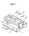
- FIG. 1 is a perspective view showing an appearance of a multi-directional operating switch in accordance with the exemplary embodiment of the present invention.
- Fig. 2 is a front view in section of the switch.
- Fig. 3 is a sectional view of the switch taken along line J-J of Fig. 2.
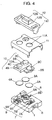
- Fig. 4 is an exploded perspective view of the switch.
- Fig. 5 is a top plan view of the switch with an operating body and a cover thereof removed.
- reference numeral 1 shows a box-like case made of an insulating resin and shaped like a rectangle as seen from the top.
- first push switch 2 hereinafter referred to as first switch 2.
- second push switch 3 Provided on the left side of the case in positions symmetrical with respect to the central axis are second push switch 3 and third push switch 4 (hereinafter referred to as second switch 3 and third switch 4, respectively).
- first bearing hole 5 in the left wall and second bearing hole 6 in the right wall are provided, as a pair of bearing portions for supporting operating body 12, which will be described later.
- first switch 2 to third switch 4 are structured as shown in Figs. 2 to 4.
- fixed contact 7 comprising outer circumferential contact 7A and central contact 7B
- fixed contact 8 comprising outer circumferential contact 8A and central contact 8B
- fixed contact 9 comprising outer circumferential contact 9A and central contact 9B are insert-molded and fixed.
- Mounted on each of outer circumferential contacts 7A, 8A, and 9A is the bottom face of the outer circumference of each of circular dome-like movable contacts 2A, 3A, and 4A made of a resilient metallic thin plate.
- the center of the bottom face of each movable contact is opposed to each of central contacts 7B, 8B, and 9B. Depressing the movable contacts from above turns on/off the switches.
- This compact contact structure can provide stable switch operation with positive tactile response.
- movable contact 3A in second switch 3 and movable contact 4A in third switch 4 have an identical shape and dimension, and substantially an equal inverting operation force.
- second switch 3 and third switch 4 have substantially an equal switch operating force.
- Driver 2B made of a rigid insulating material is mounted on the central top of movable contact 2A of the first switch 2.
- Drivers 3B and 4B made of an elastic insulating material are mounted on the central tops of movable contacts 3A and 4A of the second switch 3 and third switch 4, respectively. Depressing the contacts via these drivers 2B to 4B operates first switch 2 to third switch 4, respectively.
- driver 3B in second switch 3 and driver 4B in third switch 4 are formed of an elastic insulating material, compressive deformation of these drivers 3B and 4B made before and after the inverting action of the movable contacts 3A and 4A can increase the stroke of the depressing operation and makes it easy to set the operation stroke to predetermined amplitude.
- drivers 3B and 4B have an identical shape and dimension, and are integrally coupled by coupler 10A to form coupled driver 10. At the same time, respective drivers 3B and 4B can elastically be deformed independently. Such a structure can reduce the number of constituent components of the multi-directional operating switch as a whole and facilitates assembling thereof. In addition, this structure stabilizes the mutual position of two drivers 3B and 4B and provides an equal stroke of depressing operation for second switch 3 and third switch 4.
- FIG. 5 The top plan view of Fig. 5 shows how these first switch 2 to third switch 4 are arranged in case 1.
- Cover 11 (see Fig. 4) made of a metallic plate is placed over the top face of case 1 that houses first switch 2 to third switch 4.
- the cover has three holes 11A through which respective upper halves of drivers 2B to 4B go.
- Operating body 12 made of a resin is fitted above the cover.
- First shaft 13 and second shaft 14 extend downwardly from both longitudinal ends of rectangular plate part 12B so as to be opposed to each other, as two portions to be borne.
- the first shaft and second shaft are inserted into the above-mentioned first bearing hole 5 and second bearing hole 6 provided in left and right walls of case 1, respectively, and engaged therewith.
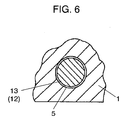
- Fig. 6 i.e. a sectional view taken along line K-K of Fig. 2, shows a structure of engagement of shaft 13 with bearing hole 5.
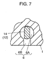
- Fig. 7 i.e. a sectional view of taken along line L-L Fig. 2, shows a structure of engagement of shaft 14 with bearing hole 6.
- first shaft 13 is shaped like a rod having a circular cross section.
- First bearing hole 5 is a circular hole having a diameter slightly larger than that of the first shaft.
- Second shaft 14 is shaped like a rod having an oval cross section with a longer diameter in the vertical direction.
- Second bearing hole 6 is shaped like a key hole.
- the key hole comprises circular section 6A having a diameter slightly larger than the longer diameter of the oval shape of second shaft 14 and downwardly projecting section 6B having a width smaller than the longer diameter of the oval shape of second shaft 14 and a slightly larger than the shorter diameter thereof.
- This structure allows operating body 12 to be pivotable around a central axis of pivot formed by a line connecting two shafts 13 and 14, i.e. two bearing holes 5 and 6.
- the side of second shaft 14 is supported so as to be vertically movable in a range below the pivotal position, only when the orientation of the oval cross section of second shaft 14 corresponds to the direction of downwardly projecting section 6B of second bearing hole 6, i.e. in the neutral position in a normal state (shown in Fig. 7).
- operating part 12A Provided on plate part 12B and above the central axis of pivot of operating body 12 is operating part 12A.
- first depressing portion 12C the bottom face of plate part 12 B on the side of second shaft 14 on the central axis of pivot of operating body 12 as seen from the top is in contact with the spherical central top portion of top end 2C of driver 2B in the above-mentioned first switch 2 (see Fig. 2).
- the multi-directional operating switch of this embodiment is structured as described above. Next, the operations thereof are described.
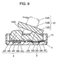
- a first operation is performed with reference to Fig. 3, i.e. one of sectional views showing the normal state of this multi-directional operating switch. Pressing force in the right direction is applied to operating part 12A of operating body 12 to tilt the operating body. Then, as shown in the sectional view of Fig. 8, operating body 12 pivots in the right direction around a central axis of pivot, i.e. the line connecting first shaft 13 borne by bearing hole 5 and second shaft 14 borne by bearing hole 6 in case 1.
- This contact action short-circuits outer circumferential contact 8A (not shown in Fig. 8) and central contact 8B, thereby actuating second switch 3.
- This signal is transferred to the circuit of the electronic equipment using this multi-directional operating switch, via leads (not shown) connected to each contact.
- first shaft 13 having a circular cross section at the one end of operating body 12 that is engaged with circular first bearing hole 5 in case 1 does not move downwardly even though operating body 12 pivots.
- the second shaft 14 having the oval cross section also does not move downwardly. This is because the orientation of the oval cross section is displaced from the direction of downwardly projecting section 6B of second bearing hole 6, as shown in the sectional view of Fig. 9, when operating body 12 pivots in the right or left direction from the neutral position (see Fig. 7) in the normal state.
- Both top end 3C of driver 3B in second switch 3 and top end 4C of driver 4B in third switch 4 are depressed by second depressing portion 12D and third depressing portion 12E, respectively, on the bottom face of plate part 12B of pivoted operating body 12, when this operating part 12A is tilted. Because theses top ends of these drivers are both spherical and thus each of depressing portion 12D and 12E positively holds down the central top portion of each driver, second switch 3 and third switch 4 perform stable operation.
- a second operation is performed with reference to Fig. 2, i.e. one of sectional views showing the normal state of this multi-directional operating switch.
- Downward depressing force is applied to operating part 12A of operating body 12.
- First shaft 13 and second shaft 14 at both ends of operating body 12 are inserted and engaged with first bearing hole 5 and second bearing hole 6 in case 1, respectively.
- first shaft 13 does not move downwardly.
- second shaft 14 moves downwardly from the neutral position. Therefore, operating body 12 tilts around a fulcrum at bearing hole 5 in case 1 bearing first shaft 13, and thereby the side of second shaft 14 goes down, as shown in the sectional view of Fig. 10.
- first depressing portion 12C on the bottom face of plate part 12B of operating body 12 depresses spherical top end 2C of driver 2B in first switch 2 that is in contact with the first depressing portion 12C on the side of second shaft 14 on the central axis of pivot of operating body 12 as seen from the top.
- This action depresses driver 2B made of a rigid insulating material downwardly.
- the depressing force applied to the central top of movable contact 2A in first switch 2 by bottom end 2D of driver 2B exceeds the inverting operation force of movable contact 2A, movable contact 2A inverts with positive tactile response and the central bottom thereof makes contact with central contact 7B, as shown Fig. 10.
- This contact action short-circuits outer circumferential contact 7A (not shown in Fig. 10) and central contact 7B, thereby actuating first switch 2.
- This signal is transferred to the circuit of the electronic equipment using this multi-directional operating switch, via leads (not shown) connected to each contact.
- movable contact 2A attempts to restore to the original shape thereof using the resilient restoring force of its own.
- This restoring force moves up plate part 12B of operating body 12 and thus restores the switch to the normal state shown in Fig. 2.
- top end 3C of driver 3B in second switch 3 and top end 4C of driver 4B in third switch 4 that are in contact with the bottom face of plate part 12B of operating body 12 on the side of first shaft 13 in positions symmetrical with respect to central axis of pivot of the above-mentioned operating body 12 are slightly depressed downwardly.
- drivers 3B and 4B are made of an elastic insulating material, slight elastic deformation of respective top ends 3C and 4C thereof accommodate to this movement. This prevents the influence on contact parts in second switch 3 and third switch 4.
- second shaft 14 having an oval cross section at the end of operating body 12 that is engaged with second bearing hole 6 in case 1 goes from circular section 6A into downwardly projecting section 6B of second bearing hole 6 shaped like a key hole, as shown in the sectional view of Fig. 11.
- Downwardly projecting section 6B is smaller than the longer diameter of the oval shape of second shaft 14 in the vertical direction and slightly larger than the shorter diameter thereof in width.
- a first operation of tilting operating part 12A to pivot operating body 12 in the right or left direction allows independent actuation of second switch 3 or third switch 4.
- a second operation of depressing operating part 12A allows independent actuation of first switch 2.
- This structure can provide the following applications. For example, with such information terminals as a cell phone, the first operation of tilting operating part 12A allows a cursor movement for selection of a menu and the second operation of depressing operating part 12A allows determination and execution of the selected menu.
- the first operation is tilting operating part 12A and the second operating is depressing operating part 12A.
- any order of operations is acceptable for convenience of the electronic equipment using this multi-directional operating switch.
- the multi-directional operating switch of the present invention can operate a plurality of push switches independently by depressing or tilting one operating part.
- this operating switch finds a wide range of applications in electronic equipment, such as various kinds of information terminals.
Landscapes
- Physics & Mathematics (AREA)
- General Physics & Mathematics (AREA)
- Engineering & Computer Science (AREA)
- Automation & Control Theory (AREA)
- Switches With Compound Operations (AREA)
Abstract
Description
Claims (6)
- A multi-directional operating switch comprising:wherein depressing said operating part allows actuation of said first push switch, and tilting said operating part to pivot said operating body in one of right and left directions allows actuation of one of said second and third push switches.an operating body supported by a pair of bearing portions provided in a case such that one end of said operating body is pivotable and an other end opposed thereto is pivotable and vertically movable in a range below a pivotal position, said operating body having:an operating part provided above a central axis of pivot;a first depressing portion provided on a bottom face of said operating body on a side of the other end on the central axis of pivot as seen from a top; anda pair of second and third depressing portions provided on the bottom face of said operating body on a side of the one end in positions symmetrical with respect to the central axis of pivot; andfirst, second, and third self-restoring push switches provided in the case in positions corresponding to said first, second, and third depressing portions;
- The multi-directional operating switch as set forth in Claim 1, wherein a borne portion at the other end of said operating body is shaped like a rod having an oval cross section longer in a vertical direction, a bearing portion in the case for bearing the borne portion is a hole shaped like a key hole, and said key hole comprises a circular section having a diameter slightly larger than a longer diameter of the oval cross section and a downwardly projecting section having a width smaller than the longer diameter and slightly larger than a smaller diameter of the oval cross section.
- The multi-directional operating switch as set forth in Claim 1, wherein any of said first, second, and third push switches is formed by mounting a circular dome-like movable contact made of a resilient metallic thin plate on a fixed contact insert-molded and fixed in the case and disposing a driver made of an insulating material on the movable contact.
- The multi-directional operating switch as set forth in Claim 3, wherein any of said second and third push switches is a type depressing the movable contact via the driver formed of an elastic insulating material.
- The multi-directional operating switch as set forth in Claim 4, wherein the drivers for said second and third push switches are integrally coupled by an elastic insulating material and elastically deformable independently.
- The multi-directional operating switch as set forth in Claim 3, wherein at least tips of the drivers for said second and third push switches are spherical and said second and third depressing portions of said operating body are in contact with respective central top portions of the tips.
Applications Claiming Priority (3)
| Application Number | Priority Date | Filing Date | Title |
|---|---|---|---|
| JP2001004666 | 2001-01-12 | ||
| JP2001004666A JP2002208331A (en) | 2001-01-12 | 2001-01-12 | Multi-directional operation switch |
| PCT/JP2002/000075 WO2002056329A1 (en) | 2001-01-12 | 2002-01-10 | Multi-directional operating switch |
Publications (2)
| Publication Number | Publication Date |
|---|---|
| EP1278221A1 true EP1278221A1 (en) | 2003-01-22 |
| EP1278221A4 EP1278221A4 (en) | 2009-11-11 |
Family
ID=18872822
Family Applications (1)
| Application Number | Title | Priority Date | Filing Date |
|---|---|---|---|
| EP02729534A Withdrawn EP1278221A4 (en) | 2001-01-12 | 2002-01-10 | MULTIDIRECTIONAL CONTROL SWITCH |
Country Status (6)
| Country | Link |
|---|---|
| US (1) | US6703571B2 (en) |
| EP (1) | EP1278221A4 (en) |
| JP (1) | JP2002208331A (en) |
| CN (1) | CN1228801C (en) |
| TW (1) | TW514943B (en) |
| WO (1) | WO2002056329A1 (en) |
Families Citing this family (14)
| Publication number | Priority date | Publication date | Assignee | Title |
|---|---|---|---|---|
| DE10151603C1 (en) * | 2001-10-18 | 2003-03-20 | Kostal Leopold Gmbh & Co Kg | Multi-way switching device for automobile applications has control elements of 2 interfitting switch modules operated by single switch operating element |
| JP3876680B2 (en) * | 2001-10-19 | 2007-02-07 | コニカミノルタビジネステクノロジーズ株式会社 | Image display device |
| JP4369784B2 (en) * | 2004-03-30 | 2009-11-25 | セイコーインスツル株式会社 | COMPOSITE SWITCH, AND ELECTRONIC DEVICE AND ELECTRONIC WATCH WITH COMPOSITE SWITCH |
| US7772512B2 (en) * | 2004-04-07 | 2010-08-10 | T.K.M. Unlimited, Inc. | Push plate assembly |
| KR101100155B1 (en) * | 2004-06-01 | 2011-12-28 | 엘지전자 주식회사 | Button assembly on control panel assembly |
| JP4720470B2 (en) * | 2005-12-09 | 2011-07-13 | パナソニック株式会社 | Compound switch |
| WO2009045442A1 (en) * | 2007-10-03 | 2009-04-09 | Fluidmaster, Inc. | Dual flush button assembly |
| CN101527214B (en) * | 2008-03-07 | 2011-02-16 | 旭丽电子(广州)有限公司 | Key structure and electronic device equipped therewith |
| TWI457963B (en) * | 2011-12-21 | 2014-10-21 | Wistron Corp | Multi-direction key assembly and electronic device |
| JP2015149150A (en) * | 2014-02-05 | 2015-08-20 | アルプス電気株式会社 | Swinging switch |
| JP6985878B2 (en) * | 2017-10-10 | 2021-12-22 | 東洋電装株式会社 | Switch device |
| CN118805234A (en) * | 2022-03-08 | 2024-10-18 | 阿尔卑斯阿尔派株式会社 | Multi-directional input device |
| DE102022122982A1 (en) * | 2022-09-09 | 2024-03-14 | Preh Gmbh | Rocker button with push function |
| DE102024104567A1 (en) * | 2024-02-19 | 2025-08-21 | Kostal Automobil Elektrik Gmbh & Co. Kg | Push- and turn-operated control element for a motor vehicle |
Family Cites Families (17)
| Publication number | Priority date | Publication date | Assignee | Title |
|---|---|---|---|---|
| JPS55146638U (en) * | 1979-04-09 | 1980-10-21 | ||
| JPS5853122A (en) * | 1981-09-24 | 1983-03-29 | 日本ビクター株式会社 | Switching mechanism |
| JPS59144840U (en) * | 1983-03-18 | 1984-09-27 | カシオ計算機株式会社 | push button switch |
| US4520240A (en) * | 1983-12-01 | 1985-05-28 | Texas Instruments Incorporated | Four-way key switch control mechanism |
| JPH031866Y2 (en) * | 1985-04-22 | 1991-01-21 | ||
| US4857881A (en) * | 1988-07-08 | 1989-08-15 | Hayes Technology | Joystick with spring disconnect |
| JP2743747B2 (en) * | 1992-12-22 | 1998-04-22 | 松下電器産業株式会社 | Operation button structure |
| US5504286A (en) * | 1994-10-12 | 1996-04-02 | Shin Jiuh Corporation | Multiple switch assembly including a rockable control plate for selectively actuating multiple microswitches |
| JP3814959B2 (en) | 1997-05-14 | 2006-08-30 | 松下電器産業株式会社 | Multi-directional operation switch and multi-directional operating device using the same |
| JP3812008B2 (en) | 1996-10-17 | 2006-08-23 | 松下電器産業株式会社 | Multi-directional operation switch and multi-directional operating device using the same |
| JP3824723B2 (en) | 1996-12-27 | 2006-09-20 | アルプス電気株式会社 | Multi-directional switch |
| JP3437054B2 (en) * | 1997-05-12 | 2003-08-18 | アルプス電気株式会社 | Multi-input switch |
| JP3937526B2 (en) * | 1997-10-21 | 2007-06-27 | 松下電器産業株式会社 | Rotating electronic components with push function |
| JP3867390B2 (en) * | 1998-03-11 | 2007-01-10 | 松下電器産業株式会社 | Multi-directional electronic component and electronic device using the same |
| JP2000149703A (en) * | 1998-11-16 | 2000-05-30 | Matsushita Electric Ind Co Ltd | Multi-circuit push-on switch and electronic device using the same |
| JP3951485B2 (en) * | 1998-12-25 | 2007-08-01 | 松下電器産業株式会社 | Rotating / pressing operation type electronic parts and electronic equipment using the same |
| TW508606B (en) * | 1999-07-27 | 2002-11-01 | Alps Electric Co Ltd | Multi-directional input device |
-
2001
- 2001-01-12 JP JP2001004666A patent/JP2002208331A/en active Pending
- 2001-12-27 TW TW090132601A patent/TW514943B/en not_active IP Right Cessation
-
2002
- 2002-01-10 WO PCT/JP2002/000075 patent/WO2002056329A1/en not_active Ceased
- 2002-01-10 CN CN02800054.4A patent/CN1228801C/en not_active Expired - Fee Related
- 2002-01-10 EP EP02729534A patent/EP1278221A4/en not_active Withdrawn
- 2002-01-10 US US10/204,540 patent/US6703571B2/en not_active Expired - Fee Related
Also Published As
| Publication number | Publication date |
|---|---|
| US6703571B2 (en) | 2004-03-09 |
| WO2002056329A1 (en) | 2002-07-18 |
| US20030155217A1 (en) | 2003-08-21 |
| TW514943B (en) | 2002-12-21 |
| CN1455941A (en) | 2003-11-12 |
| JP2002208331A (en) | 2002-07-26 |
| EP1278221A4 (en) | 2009-11-11 |
| CN1228801C (en) | 2005-11-23 |
Similar Documents
| Publication | Publication Date | Title |
|---|---|---|
| JP4882842B2 (en) | Multi-directional input device | |
| US6703571B2 (en) | Multi-directional operating switch | |
| US6348664B2 (en) | Multidirectional switch whose stem can be tilted and pushed | |
| KR20010015683A (en) | Multiple electric switch with single actuating lever | |
| JP3531540B2 (en) | Multi-directional operation switch | |
| JPH09147666A (en) | Push-on switch | |
| US6809272B2 (en) | Double action push switch | |
| JP2002063830A (en) | Push button switch and composite switch using the same | |
| JP2005302462A (en) | Multi-directional operation switch | |
| US20050000783A1 (en) | Multi-directional slide switch | |
| JP2003257270A (en) | Switching device | |
| KR100279397B1 (en) | Multi-directional switch | |
| JP3812008B2 (en) | Multi-directional operation switch and multi-directional operating device using the same | |
| US7994441B2 (en) | Compound operation input device | |
| JP2010003424A (en) | Multi-directional input device | |
| JP2001006497A (en) | Multidirectional switch | |
| JPH07245042A (en) | Multi-way input switch | |
| JP3937670B2 (en) | Multi-directional operation switch | |
| JP5551578B2 (en) | Multi-directional switch device | |
| JP3814959B2 (en) | Multi-directional operation switch and multi-directional operating device using the same | |
| CN114787953B (en) | Pushing mechanism of push switch and push switch | |
| JP4720470B2 (en) | Compound switch | |
| JP4375381B2 (en) | Multi-directional input device and electronic apparatus equipped with the same | |
| JP2022043622A (en) | Push switch | |
| JP3948882B2 (en) | Multi-directional input switch |
Legal Events
| Date | Code | Title | Description |
|---|---|---|---|
| PUAI | Public reference made under article 153(3) epc to a published international application that has entered the european phase |
Free format text: ORIGINAL CODE: 0009012 |
|
| 17P | Request for examination filed |
Effective date: 20020807 |
|
| AK | Designated contracting states |
Kind code of ref document: A1 Designated state(s): AT BE CH CY DE DK ES FI FR GB GR IE IT LI LU MC NL PT SE TR |
|
| RBV | Designated contracting states (corrected) |
Designated state(s): AT BE CH CY DE FI FR GB LI SE |
|
| RAP1 | Party data changed (applicant data changed or rights of an application transferred) |
Owner name: PANASONIC CORPORATION |
|
| RIC1 | Information provided on ipc code assigned before grant |
Ipc: H01H 25/00 20060101ALI20090908BHEP Ipc: H01H 25/04 20060101AFI20020723BHEP Ipc: G06F 3/033 20060101ALI20090908BHEP |
|
| A4 | Supplementary search report drawn up and despatched |
Effective date: 20090914 |
|
| STAA | Information on the status of an ep patent application or granted ep patent |
Free format text: STATUS: THE APPLICATION IS DEEMED TO BE WITHDRAWN |
|
| 18D | Application deemed to be withdrawn |
Effective date: 20091212 |